V2 Rocket History
  • Home
  • Blog
  • Galleries
    • Anatomy of the V2
      • The 18 pot injection head
    • Missile guidance
    • Steering and trim
    • V2 Turbopump
      • Turbopump
      • Turbopump 3D CAD
      • Turbopump: original drawings
    • Thrust chamber
    • Valves
    • Fuel injector inserts
    • Peenemünde
      • Development works
      • Karlshagen
      • Werk Süd (South works) region
      • Enigmas
  • All video posts
  • Contact
News Ticker
  • [ June 11, 2024 ] V2 Rocket Photos Decoded: Episodes 1 & 2 V2 missile combat history
  • [ April 20, 2018 ] How a gyroscope guides a rocket Rocket stuff for education and fun
  • [ June 17, 2025 ] The V2 rocket’s secret afterbuner A4-V2 missile technology
  • [ June 16, 2024 ] The riddle of the V2 rocket shape A4-V2 missile technology
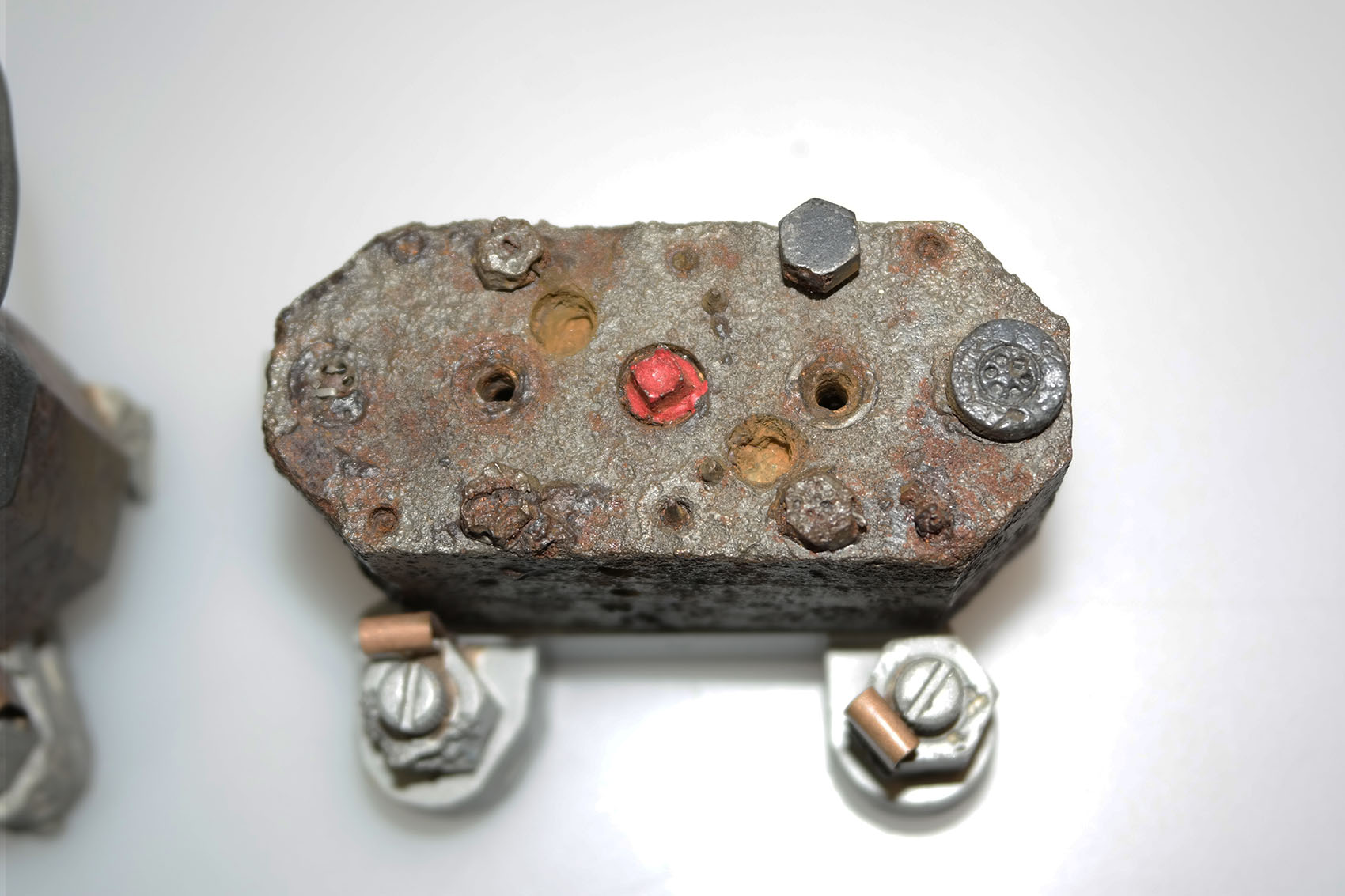
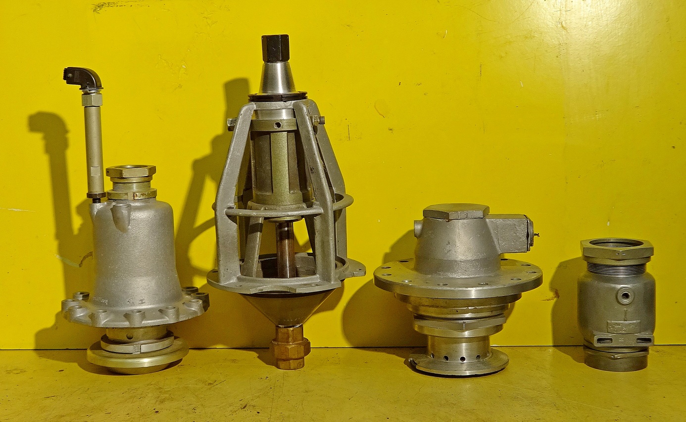
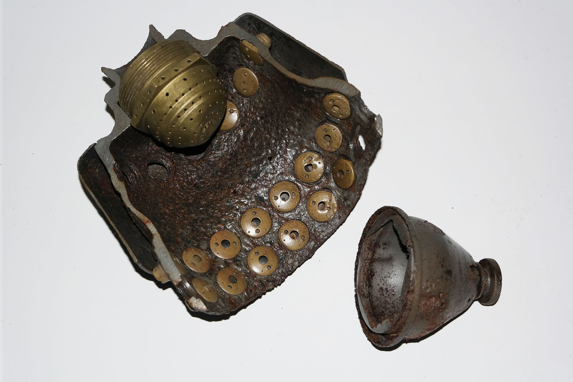
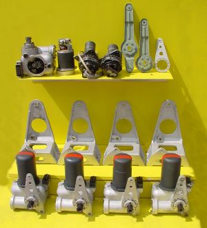
  • [ June 15, 2024 ] Dissecting a V2 rocket steam pot A4-V2 missile technology

A4-V2 Hydraulic servo and electric trim motor

Water jet from plain 2mm feed hole
Set of sample V2 fuel injectors
'Einheitskopf' Type 4B Injector head fragment
2131E Inserts in burner cup Peenemünde workshop relic
V2 rocket two part fuel injector
V2 fuel injector swirl inlet hole spec.
Unknown helical part
Chain and hook clamp - unknown use
V2 missile engine wreckage
V2 fin relic near F1
V2 missile debris field SE of F1
V2 missile debris near F1
V2 aerodynamic fin relics
V2 Light-Beam radio environment case relic South of F1
V2 rocket thrust control ring with fin and vane servos
Remains of 36 volt battery cells used on the V2 to power onboard equipment. ©THBC
Jet vane and trim fin servos and trim motor-gearboxes used on the V2 missile
A4-V2 air rudder detail. ©THBC
Restored fin no 2 or 4 showing trim motor and chain drive linkage
Graphite jet vane, heat sink support and bearing housing
Cell from 50 volt lead acid command or signalling battery
V2 jet vane hydraulic servo wreckage
Part of prototype 25-Ton injector head
Aluminium head part from 1941/42
Aluminium head with 68 inserts from 1940/41
Injector relic showing cup and injector inserts
V2 injector head from 1945
The heating system shown here is found only rarely on surviving relics
Hydraulic servo relics from Mittelwerk
Gear pump showing flow adjusters and ceramic heater elements
Main valves fuel and LOX
V2 rocket cutaway mixer pot showing fuel and LOX injectors
Cutaway of injector basket showing fuel injectors and fitted LOX cap
Main fiel and LOX propellent valves
Hydraulic servo impact debris
V2 missile thrust chamber or oven
Examination of V2 thrust chamber
Injector pots V2 rocket 1945
V2 rocket motor relic from 1945
Fin and jet vane servo: Hydraulic gear pumps
V2 Missile relics

Categories: Combustion, V2 Missile relics, Electrical connection, Mystery part, Peenemünde-Usedom-locations, Sub-assemblies, Missile guidence, Propellant flow, Guidence

Albums: Testing fuel injectors, V2 rocket fuel injector inserts, The Enigmas, Peenemünde research: Werk Süd (South works) region, A4-V2 Hydraulic servo and electric trim motor, Missile guidance equipment, A4-V2 Injection head, combustion chamber, and nozzle, Valves

Tags: #Combustion and injection #Propellent injector system #Test procedures #V2 Missile relics #A4-V2 supply contractor #Fertigungshalle Eins (F1) #HAP #HVP #Peenemünde #Werk Sud (South Works) #Usedom #light beam device #Control surface servos #LEV-3 gyroscope system #Mittelwerk Nordhausen #Propellant Valves #V2 in combat #Thrust chamber

  • Previous
  • Next
Jet from 2mm drilled fuel feed hole
Robert J Dalby
category:Combustion
album:Testing fuel injectors
Water jet from plain 2mm feed hole
Set of sample V2 fuel injectors
'Einheitskopf' Type 4B Injector head fragment
2131E Inserts in burner cup Peenemünde workshop relic
V2 rocket two part fuel injector
V2 fuel injector swirl inlet hole spec.
Unknown helical part
Chain and hook clamp - unknown use
V2 missile engine wreckage
V2 fin relic near F1
V2 missile debris field SE of F1
V2 missile debris near F1
V2 aerodynamic fin relics
V2 Light-Beam radio environment case relic South of F1
V2 rocket thrust control ring with fin and vane servos
Remains of 36 volt battery cells used on the V2 to power onboard equipment. ©THBC
Jet vane and trim fin servos and trim motor-gearboxes used on the V2 missile
A4-V2 air rudder detail. ©THBC
Restored fin no 2 or 4 showing trim motor and chain drive linkage
Graphite jet vane, heat sink support and bearing housing
Cell from 50 volt lead acid command or signalling battery
V2 jet vane hydraulic servo wreckage
Part of prototype 25-Ton injector head
Aluminium head part from 1941/42
Aluminium head with 68 inserts from 1940/41
Injector relic showing cup and injector inserts
V2 injector head from 1945
The heating system shown here is found only rarely on surviving relics
Hydraulic servo relics from Mittelwerk
Gear pump showing flow adjusters and ceramic heater elements
Main valves fuel and LOX
V2 rocket cutaway mixer pot showing fuel and LOX injectors
Cutaway of injector basket showing fuel injectors and fitted LOX cap
Main fiel and LOX propellent valves
Hydraulic servo impact debris
V2 missile thrust chamber or oven
Examination of V2 thrust chamber
Injector pots V2 rocket 1945
V2 rocket motor relic from 1945
Fin and jet vane servo: Hydraulic gear pumps
Close Full
Description

Each burner cup of the V2 rocket engine injector system has forty-four brass inserts, but each cup also has twenty-four 2mm diameter plain holes, 30 deg apart, drilled into the cup's central wall. To mimic this for testing purposes, we created a brass insert that has a base with just a 2mm central hole. The base is sized to be consistent with the 4 to 5mm cup wall. V2RH image

More
#Combustion and injection#Propellent injector system#Test procedures#V2 Missile relics
Location
Keyboard Shortcuts Dismiss
  • SSlideshow
  • MMaximize
  •  Previous
  •  Next
  • escClose
	
© Terms of Use

Categories

Sign up for our newsletter

Recent Posts

  • The V2 rocket’s secret afterbuner
    June 17, 2025 0
  • The riddle of the V2 rocket shape
    June 16, 2024 0
  • Dissecting a V2 rocket steam pot
    June 15, 2024 0
  • The ghost of the V2 in the Rocketdyne A-7
    June 15, 2024 0
  • Building the V2 rocket engine
    June 15, 2024 0
  • A72 rocket launch switch
    A4 / V2 Rocket in detail: A72 launch switch
    June 15, 2024 0
  • Big Ben 22
    V2 Rocket Photos Decoded: Episodes 1 & 2
    June 11, 2024 0
  • A4 V2 missile turbopump and Walter steam drive
    A4 / V2 Rocket in detail: Turbopump
    July 5, 2019 0
  • 3D CAD modelling the V2 rocket turbopump
    April 6, 2019 0
  • This month’s question
    March 30, 2019 6
  • Anatomy of the V2 missile
    March 26, 2019 0
  • V2 rocket brass fuel injection inserts
    Testing V2 rocket fuel injectors
    March 20, 2019 0
  • A close-up look at the V2 rocket engine’s fuel injector inserts
    March 11, 2019 0
  • This month’s question for you
    February 28, 2019 3
  • Aerodynamic fin parts with bearing and top-of-fin counterbalance weight visible on the right
    Peenemünde: F1 the giant V2 missile factory at Werk Süd
    May 11, 2018 Comments Off on Peenemünde: F1 the giant V2 missile factory at Werk Süd
This month’s question

Can you help us identify the object below?

Mystery object
This part has a helicoid or screw shape, it seems that it might have been designed to screw into a pipe of some kind. But do you know what it is, and what it did? If you do, click on it and tell us.
Don’t miss a thing – sign up for the newsletter
Privacy policy: We collect e-mail addresses of subscribers to our Newsletter so we can send e-mails from V2rockethistory.com. We use the e-mail addresses only to distribute our electronic newsletter and other information relevant to our website and for no other purpose.

V2rockethistory.com does not sell, rent, or lend e-mail addresses of our users to anyone - ever.

Copyright: V2 Rocket History