Analysing and transcribing the original 75-year old V2 rocket turbopump technical drawings for modern 3D modelling systems.
Computer Aided Design (CAD) has a surprisingly long history but the modern 3D CAD we see everywhere today did not take root until the late 90s and start of the millennium.
Since I began my full-time mechanical design and engineering career in the early 90s, 3D CAD modelling has become ubiquitous. It has evolved into a powerful way of perceiving the human-made world of shape and function, and not just in its original theatre within engineering communities, but in the general population as well. For some years now even products as familiar as a toothbrush can’t be promoted without a 3D solid or wire model pirouetting in a TV advertisement!
What is certain is that if the V2 missile were being designed today, just like any other aerospace project – 3D CAD modelling software would be the tool of choice for defining both its form and documenting its progress. So what better way to visualise the historical A4/V2 documents for today’s audience than to show them in the visual language of modern aerospace engineering – the 3D CAD model.

My interest in rockets was inspired by my father, who was a machinist and master mechanic from Frankfurt am Main. When I was a boy, he would often rattle off the history of the German team’s achievements in extraordinary detail. He passed in 1990. I’ve wanted to draft the A4/V2 since around 1992 when I began drafting full time.
Much has happened in the intervening years, and nothing less than a revolution has taken place with how we visualise engineering design. What was just a pleasant idea at the back of my mind did not crystallise into a practical possibility until a few years ago when Tracy Dungan at v2rocket.com steered me towards the growing archive of V2 documents and plans being made available at Digipeer.de.
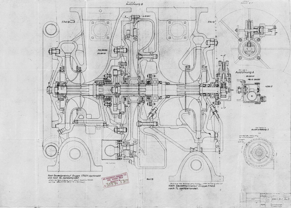
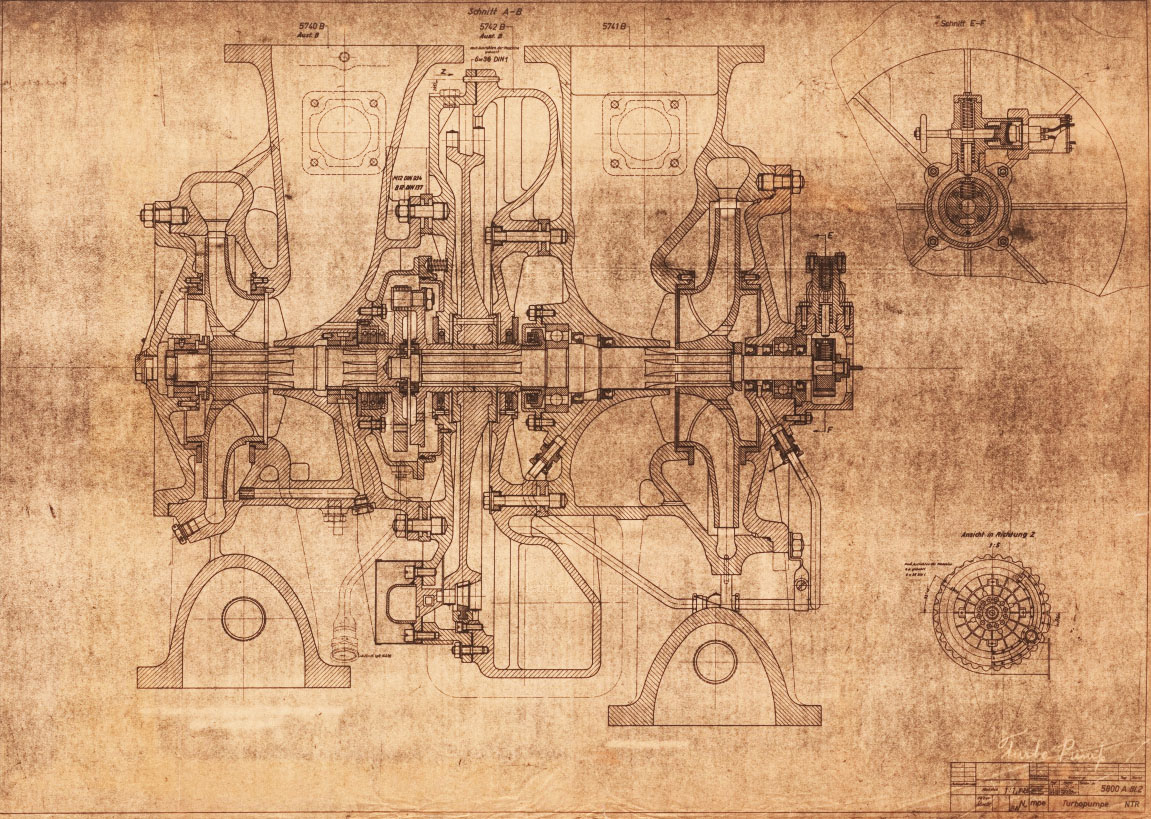
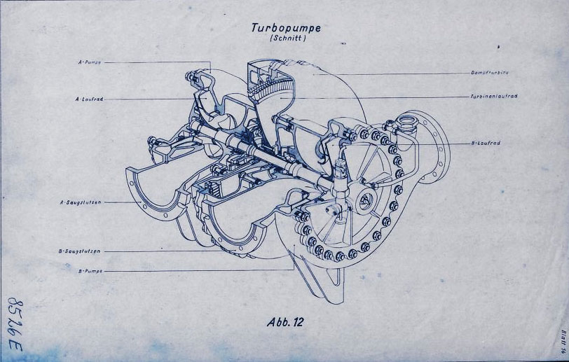
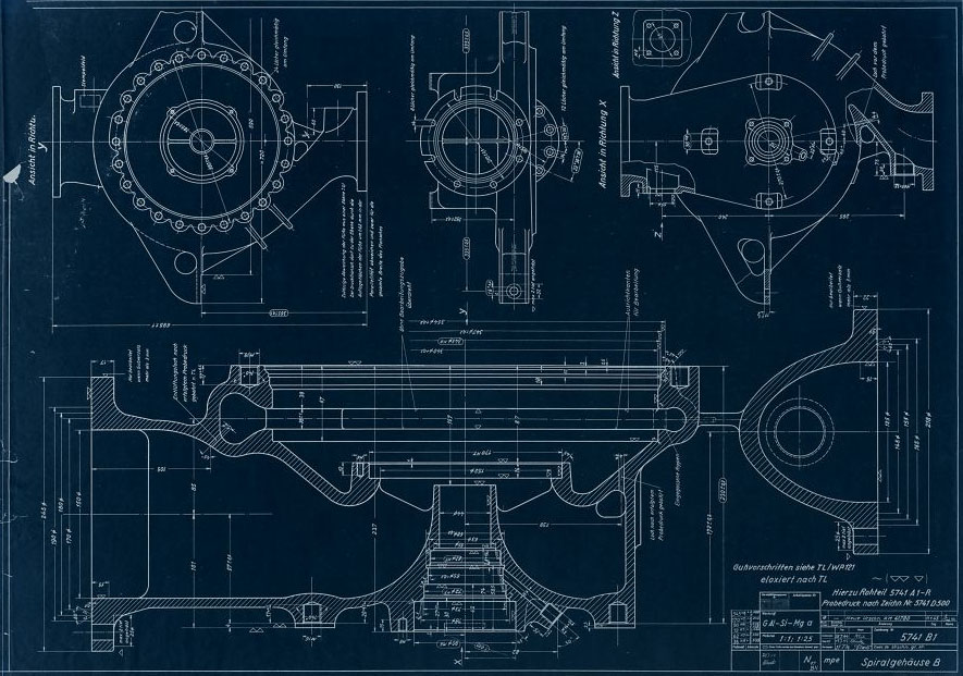
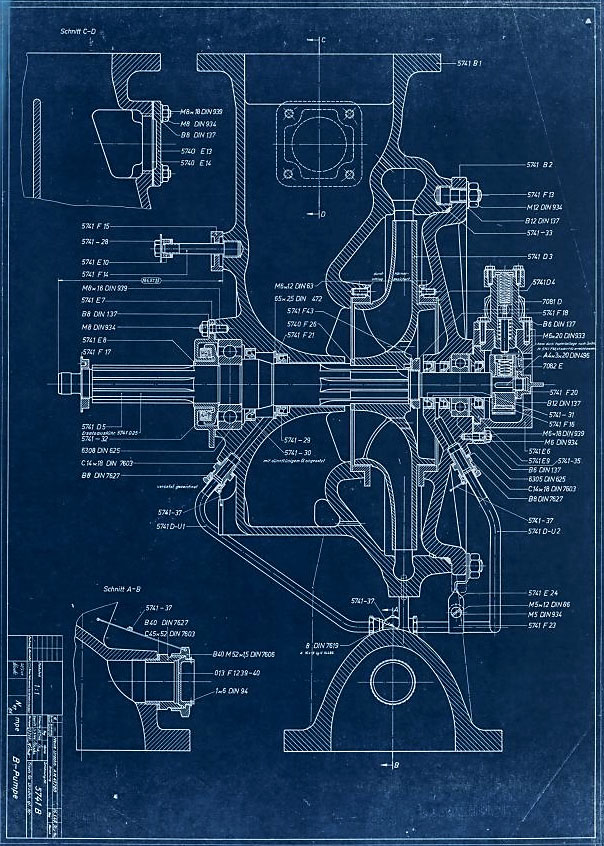
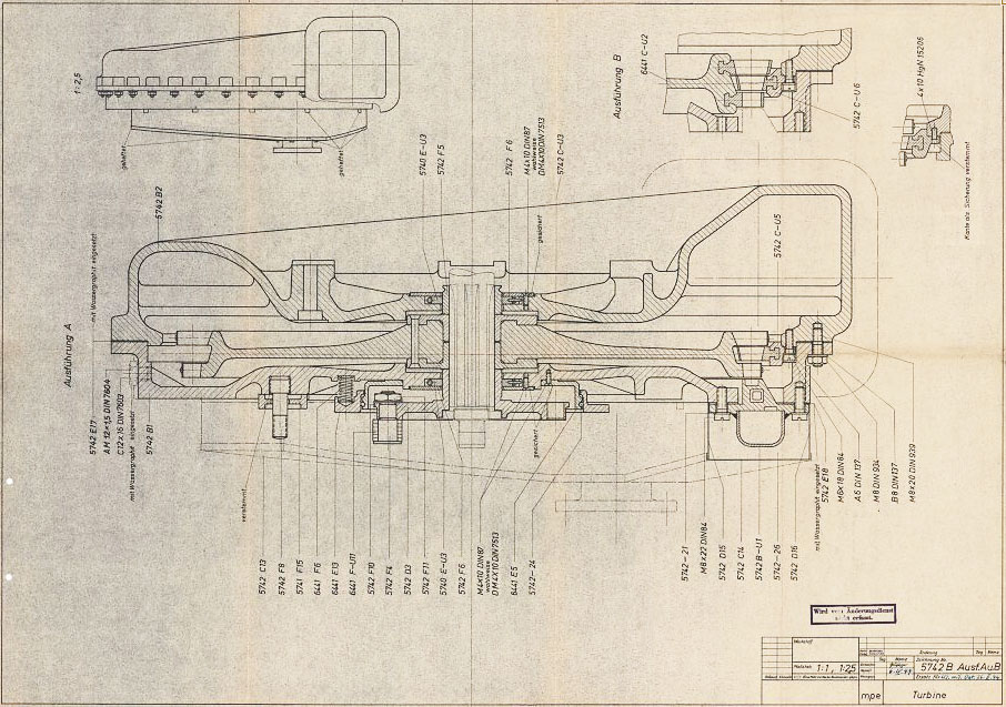
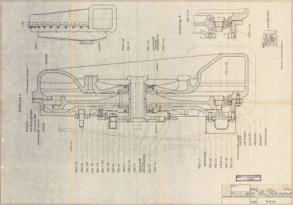
The gallery below has a small sample of the 1000s of original technical drawings of the V2 turbopump made mainly at the army facility at Peenemünde from 1936 to 1945.


I’ve stopped counting the time I spend on the turbopump project after I passed the 100-hour mark, I decided that watching the clock was counterproductive – as this was all on the fun side of the ledger anyway, and besides, there’s nobody to bill!
Start with the hard stuff first
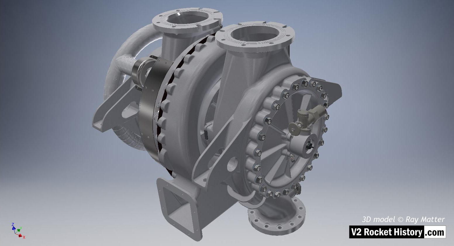
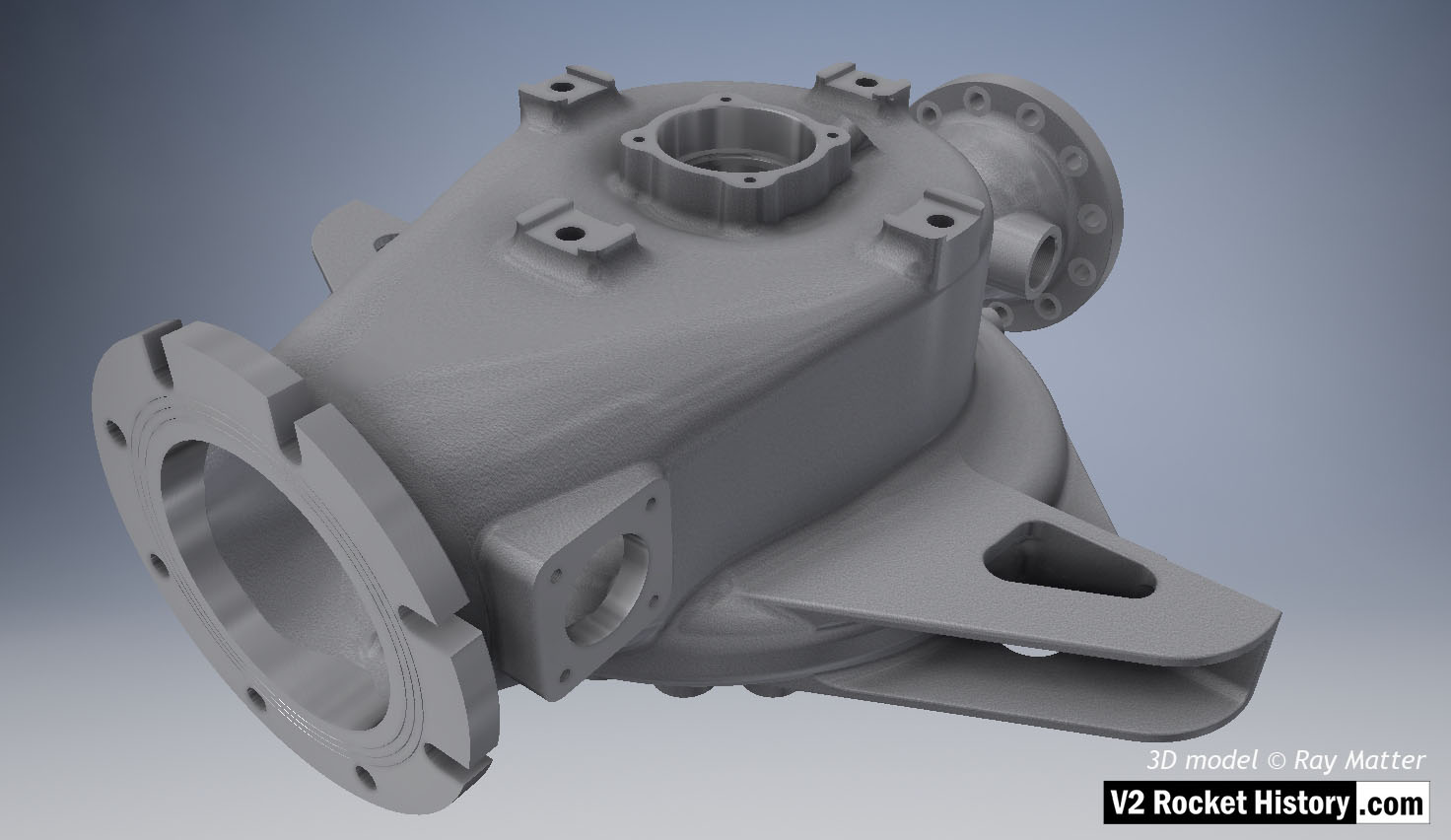
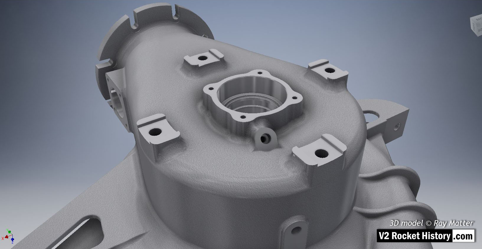
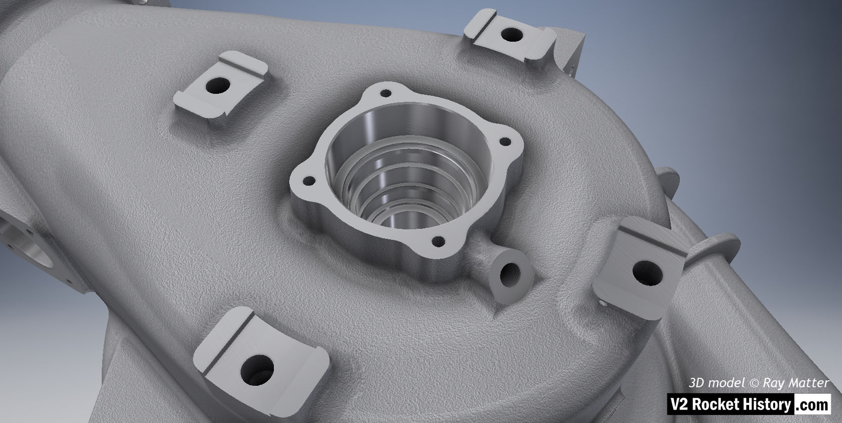
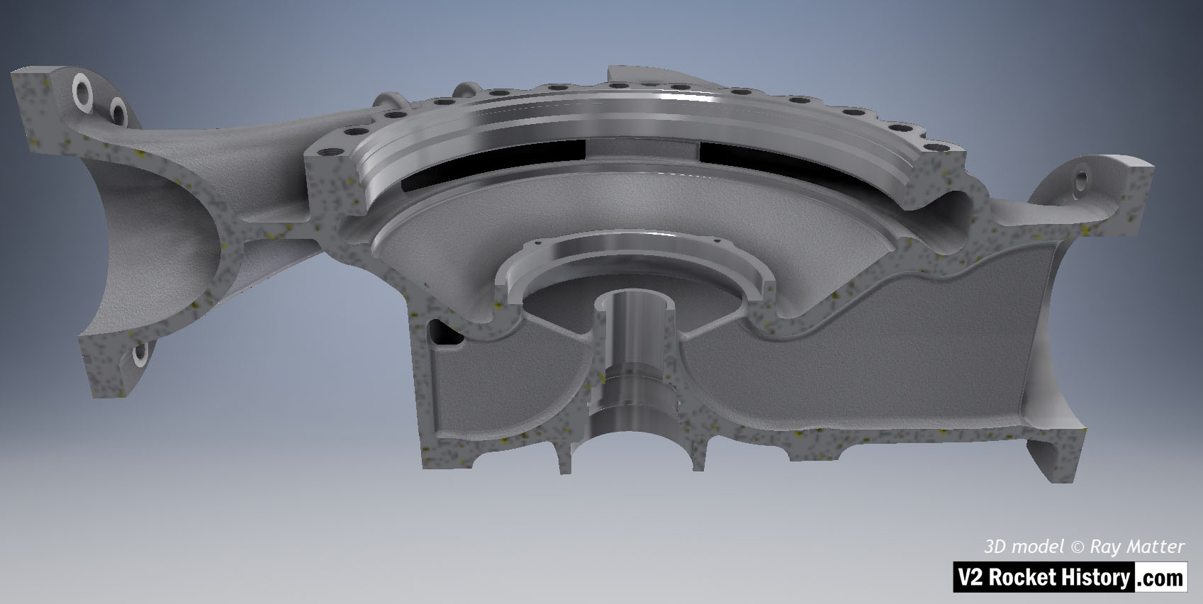
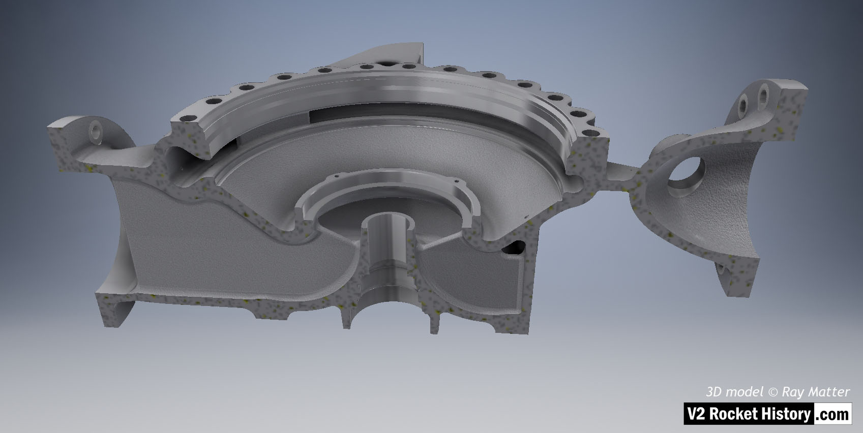
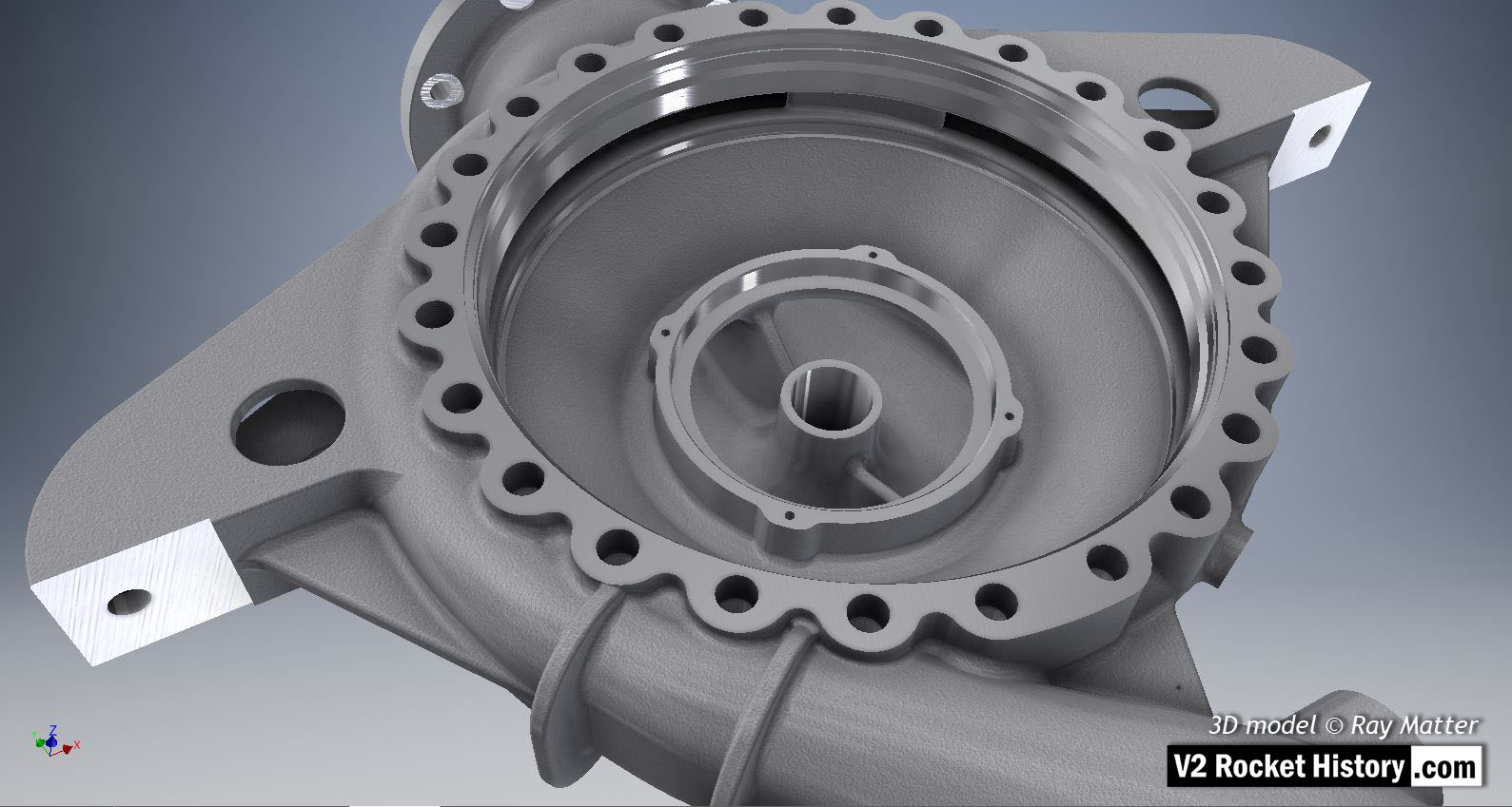
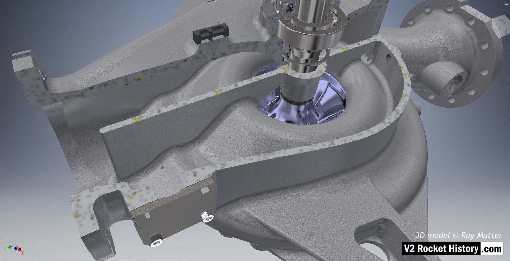
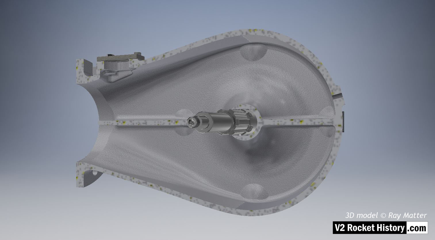
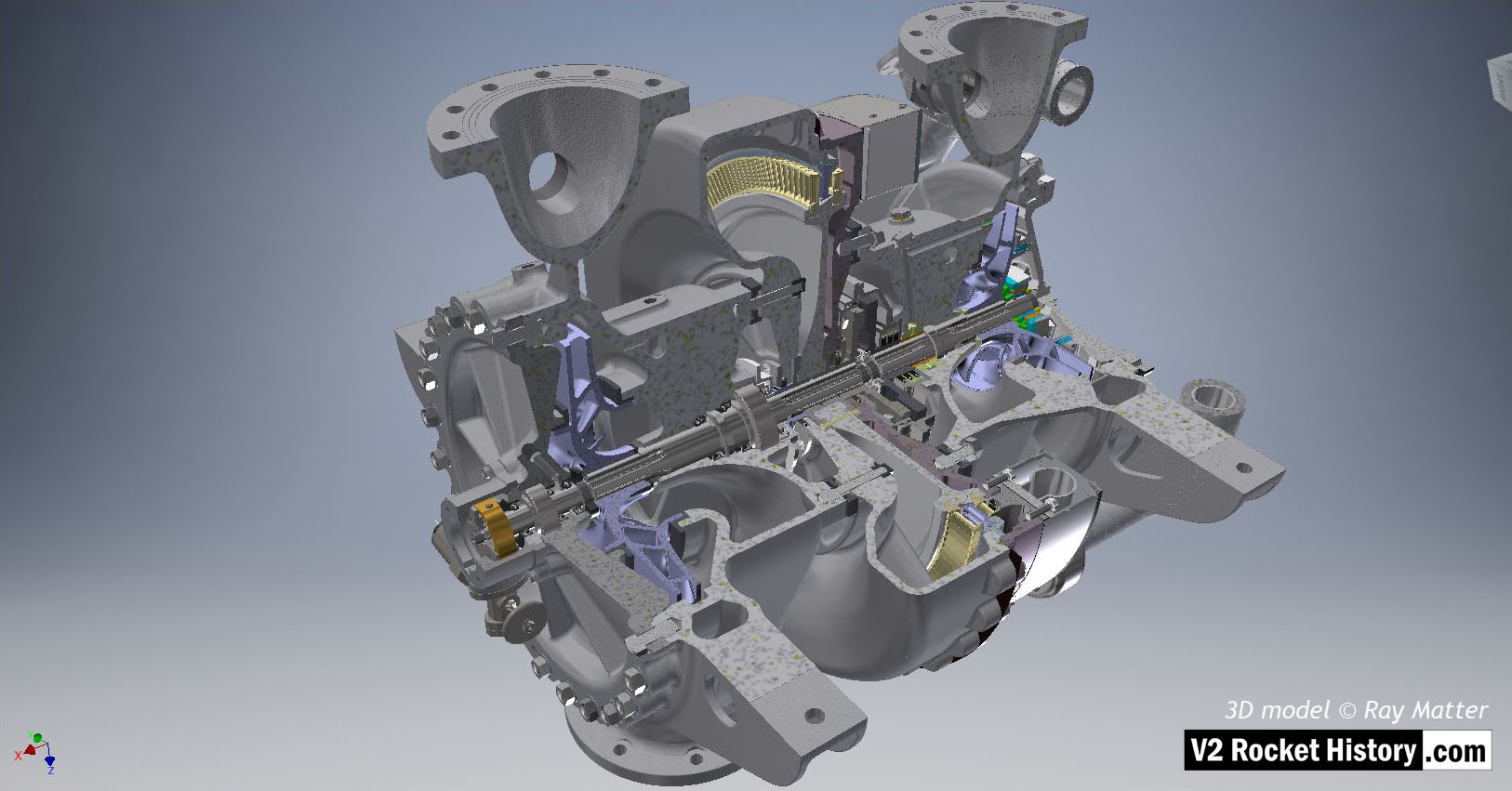
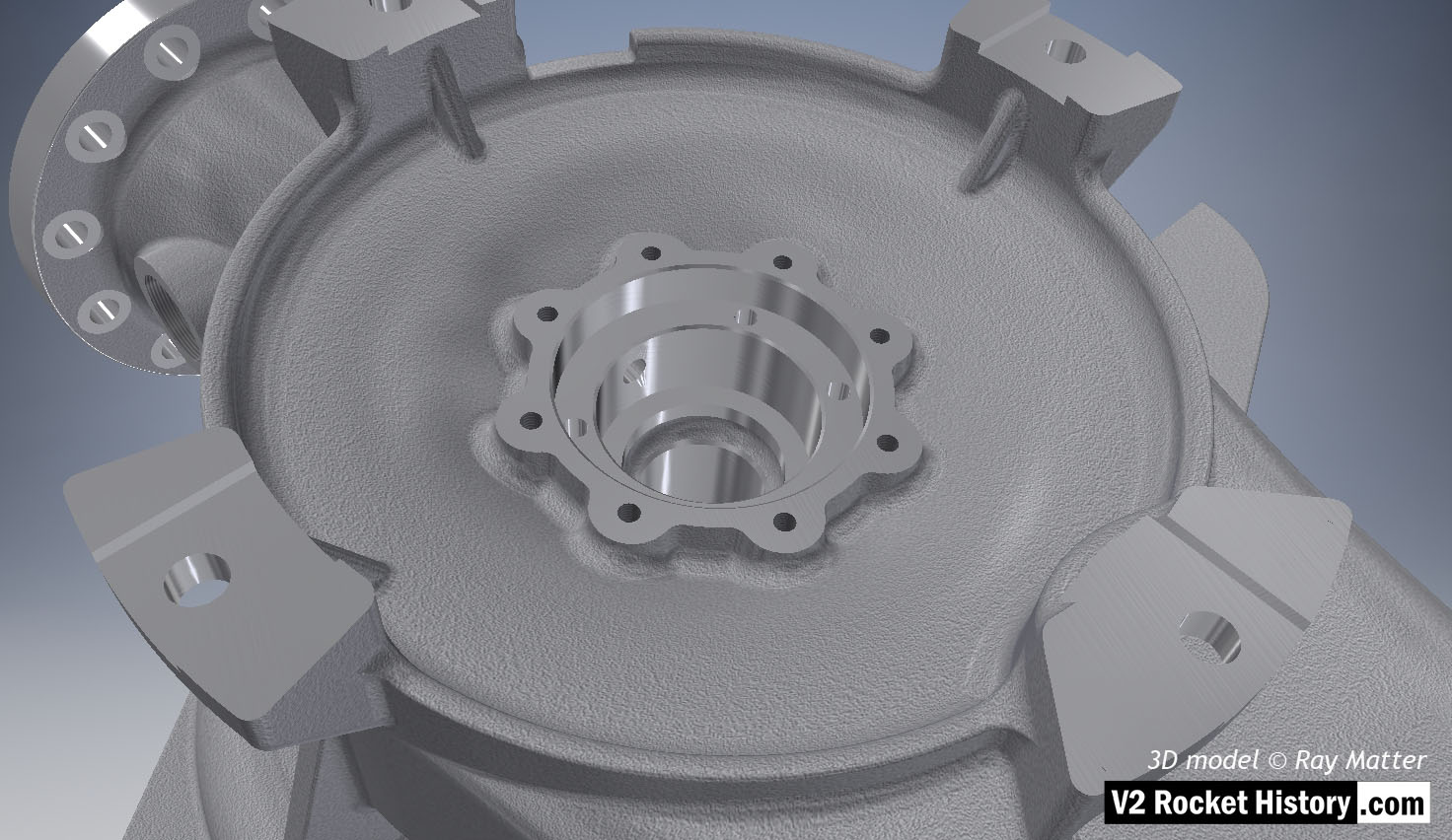
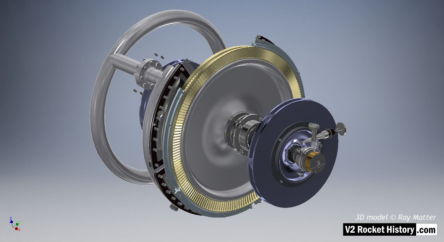
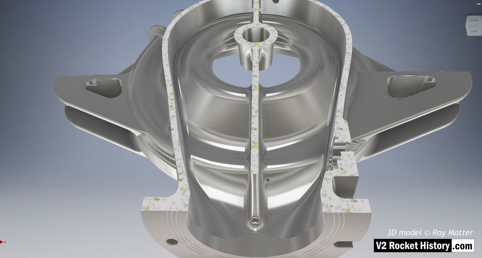
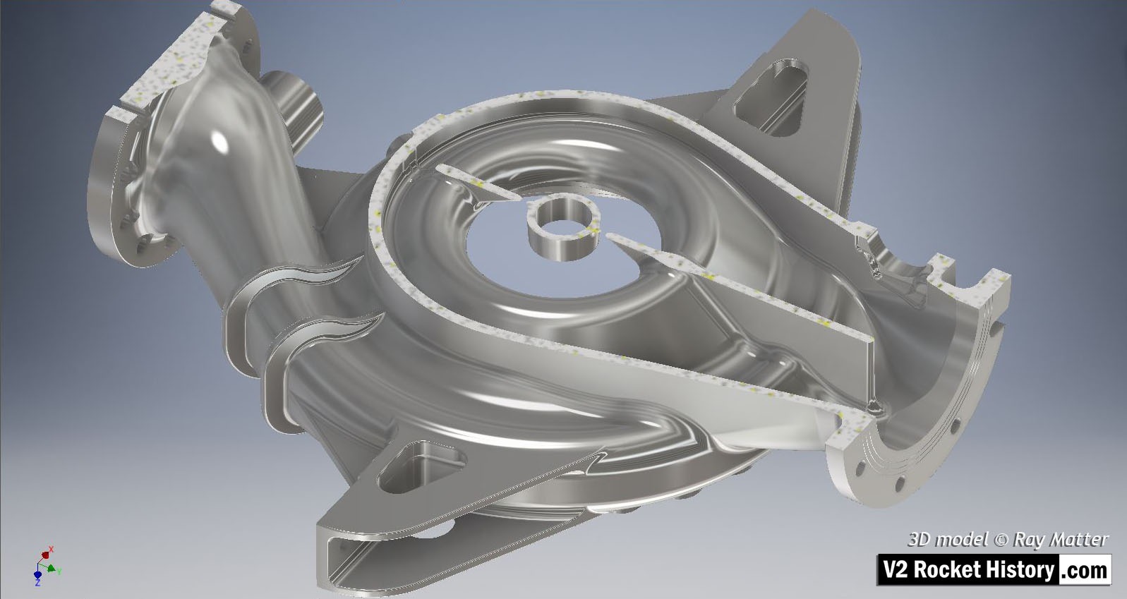
When I began my A4/V2 project, I decided to start with the most challenging parts, as I did not want to complete the more accessible parts in one program, only to find that I would have to change programs later on. And the most difficult components to translate to a modern CAD system are the cast pieces, like the main body parts of the TP, as they reflect the work of foundry pattern makers of the day, which pose as a challenge for modelling with the fillet and round commands in any advanced CAD program.

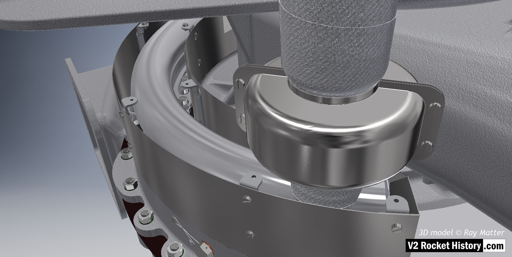
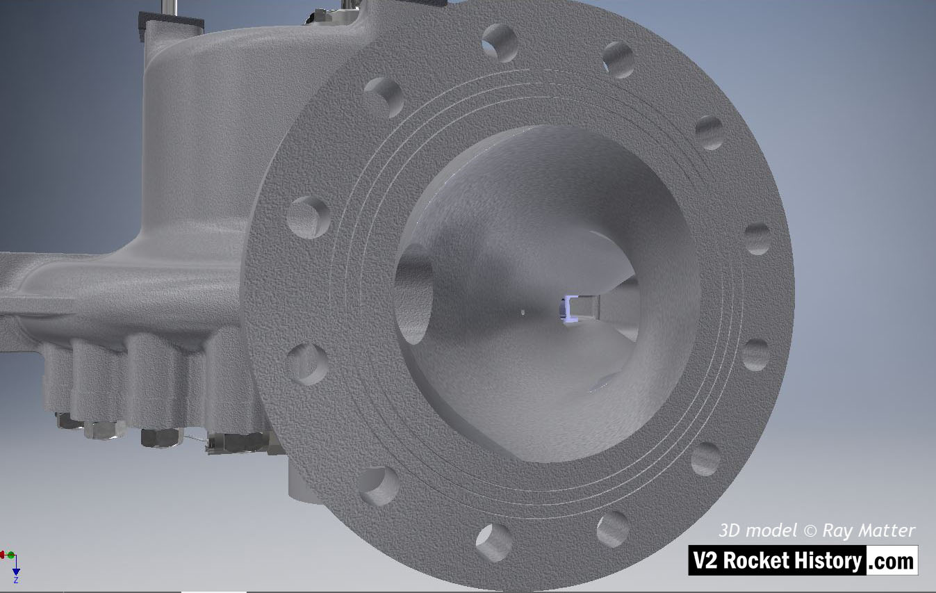
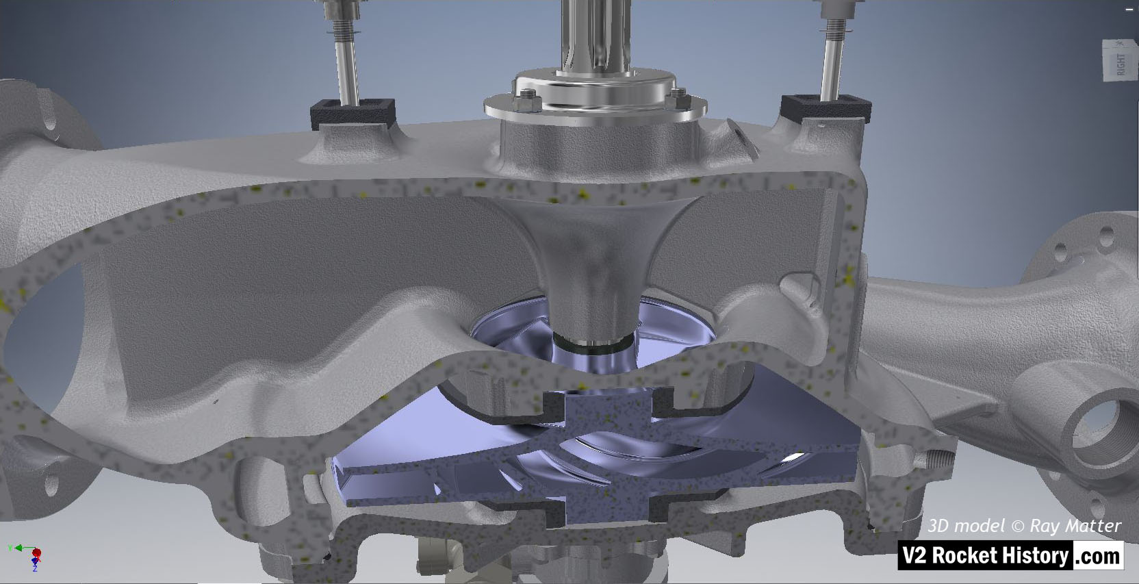
Fastenings, turbine case contact furniture, splined turbine connection shaft, and shaft seal cap are also shown. 3D model Ray Matter
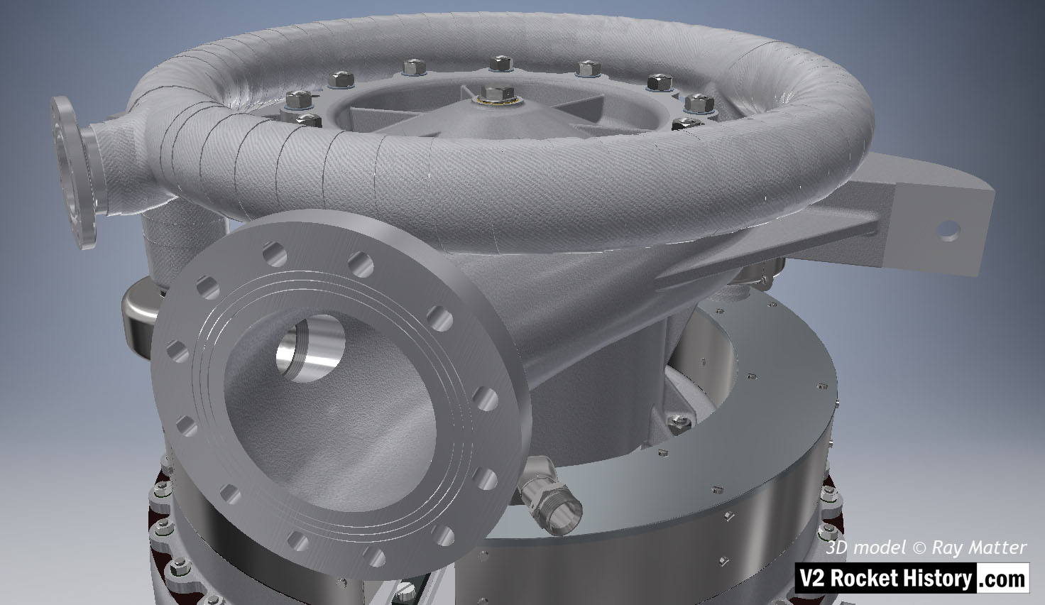
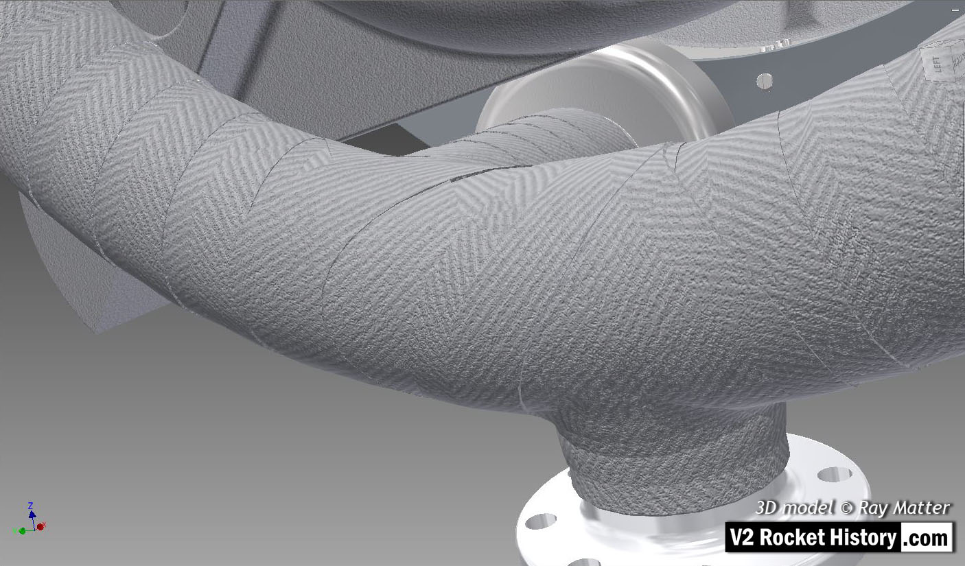
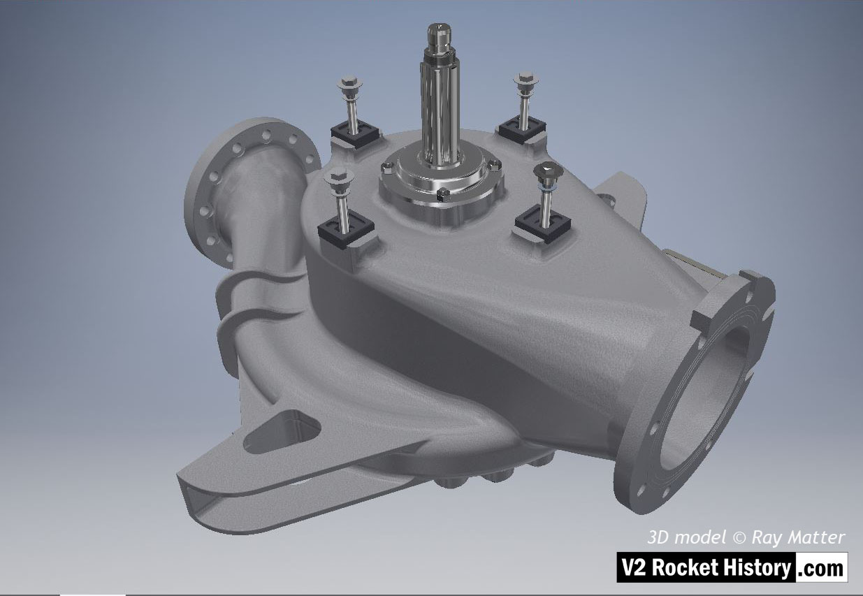
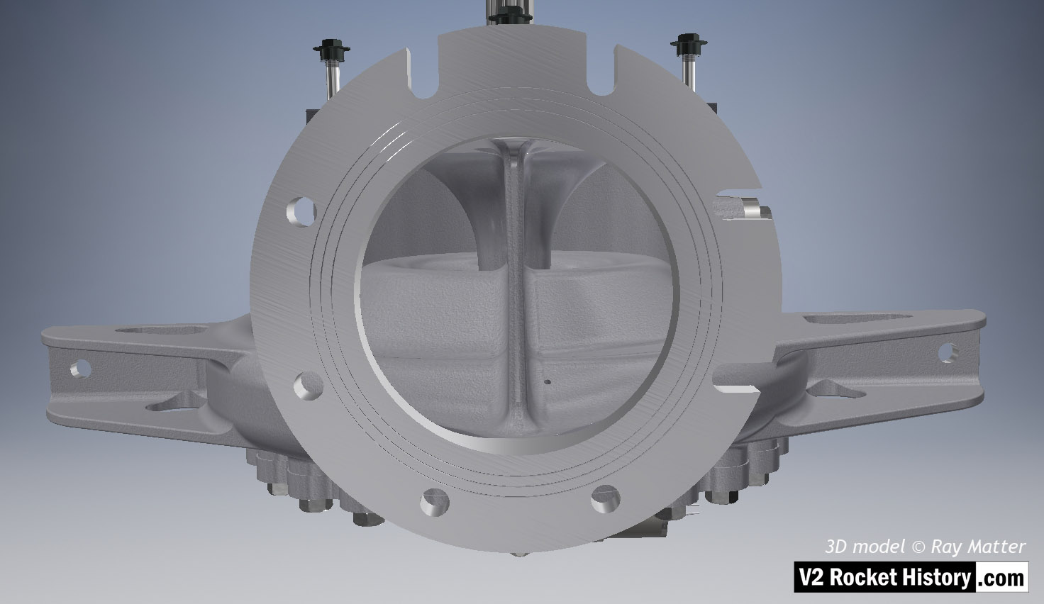
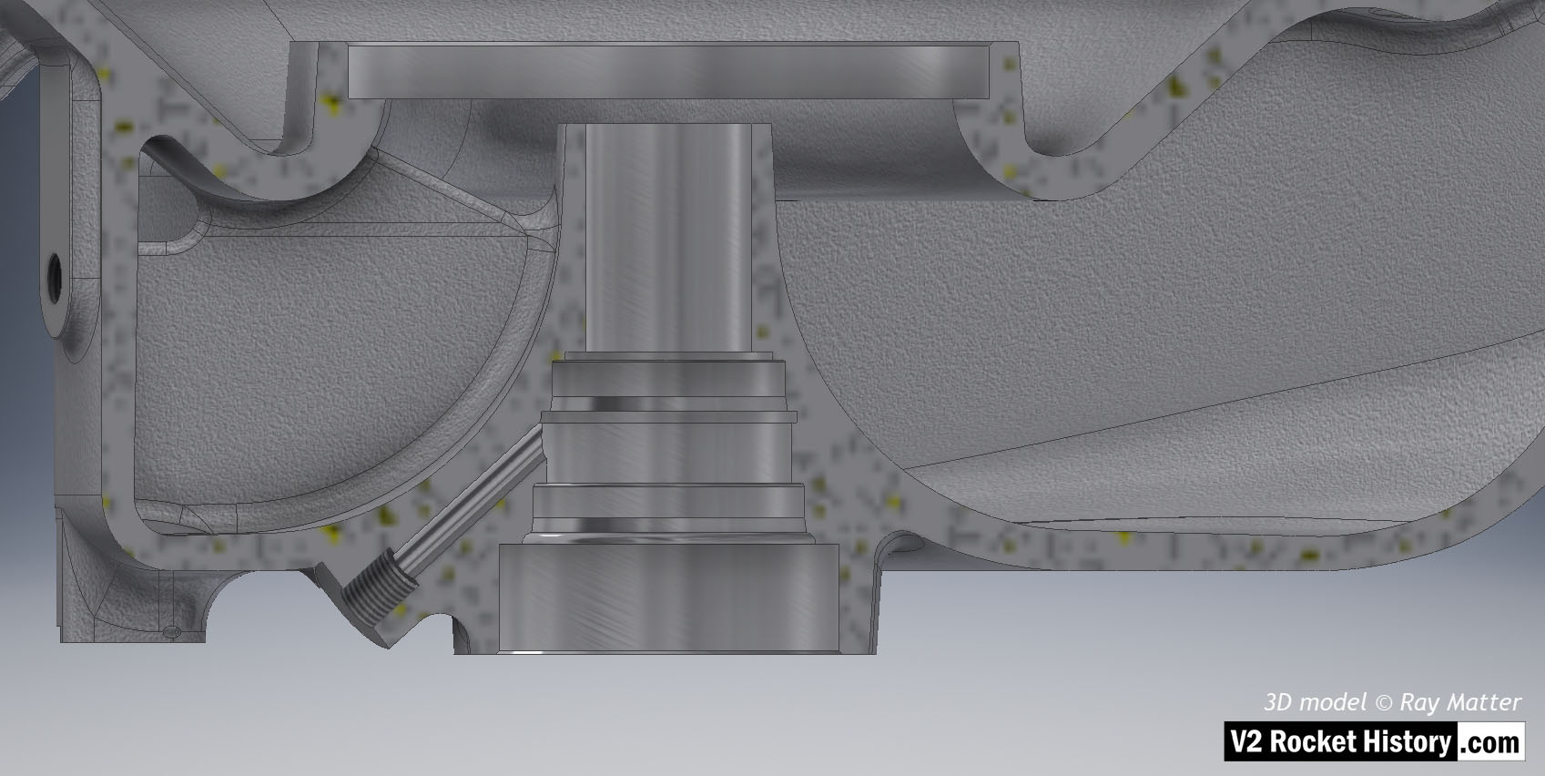
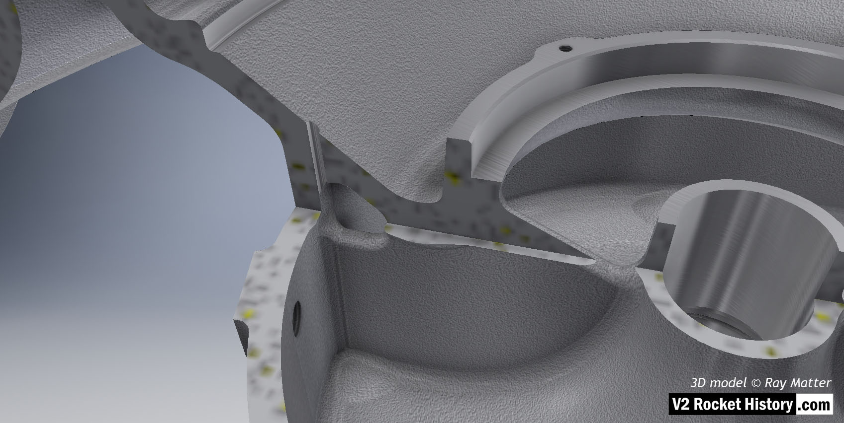
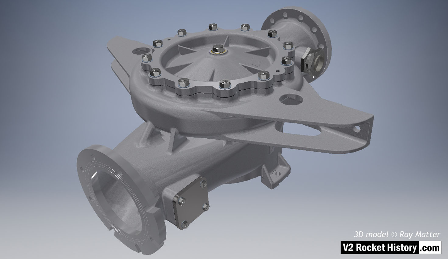
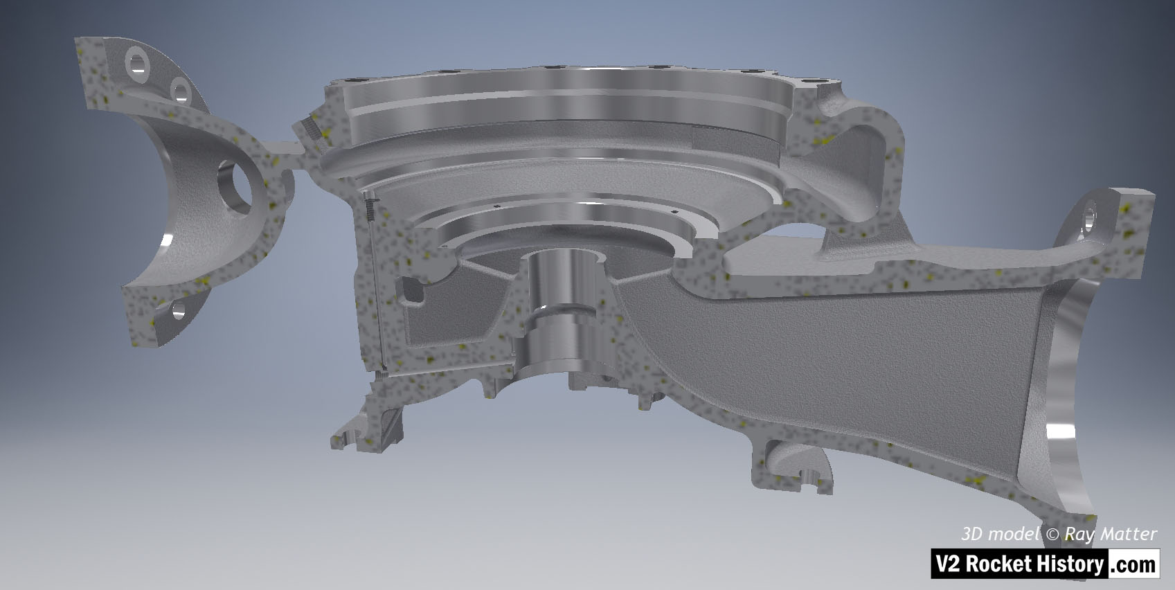
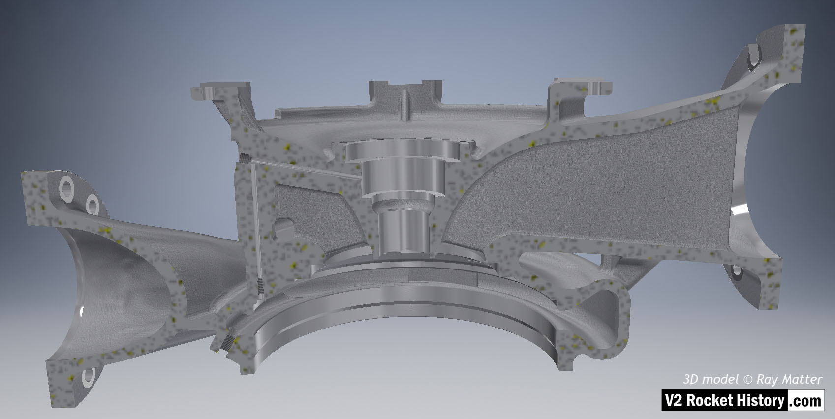
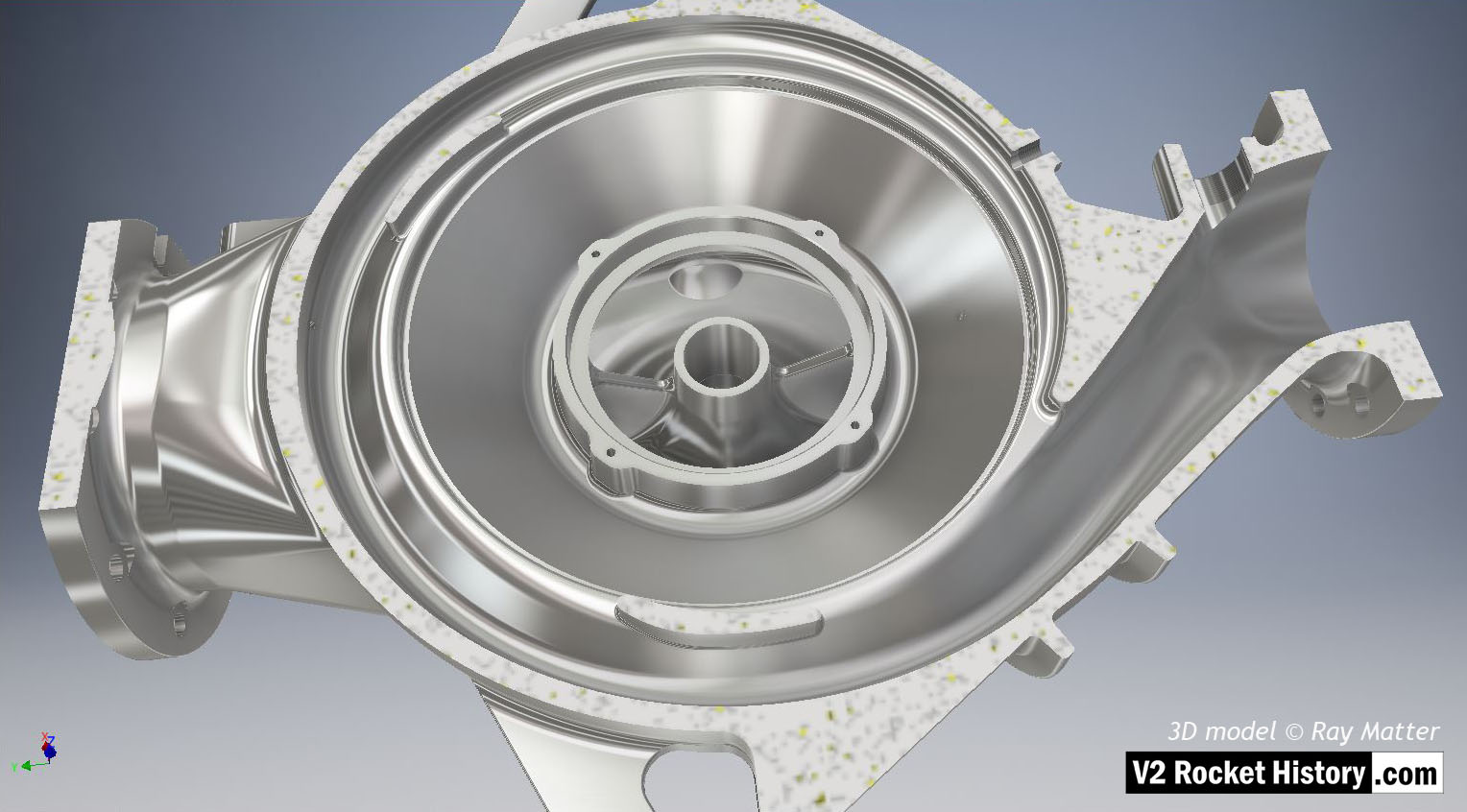
I immediately ran into issues with body shape on the connections between the volute chamber and both inlets when forcing the program to use the radii as specified on the original drawings. I had promised myself I would translate the shape with maximum accuracy and fidelity to the original drawings. I tried both Solidworks and Inventor at that time and had greater success with Inventor, so naturally, I carried on with Inventor.
The old-school designers in the Peenemünde drawing offices developed a real skill for converting their 3D ideas into flat 2D drawings, but I think the draughting office would have derived the pump body shapes from the castings supplied by the primary contractor Klein Schanzlin & Becker (KSB). That’s to say, the final contours of the housings are the product of the engine demand metrics playing against the limitations of aluminium casting technique, and these certainties would have originated with KSB and their foundry’s expertise rather than the Army drawing office.
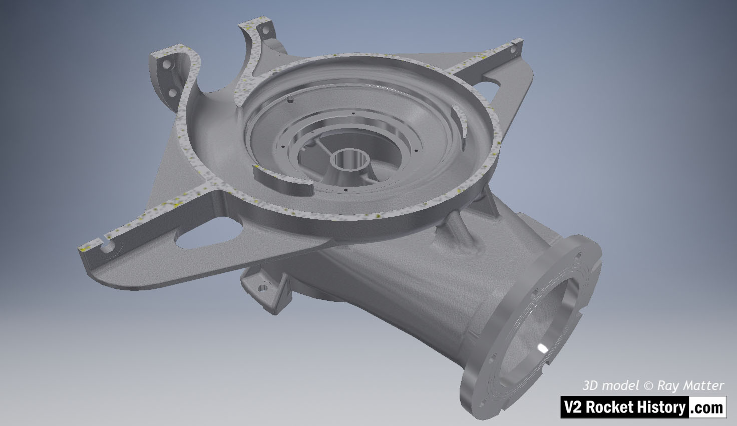
If we were designing such housings for a modern product in CAD today, we would let the program drive many of these variable radii with its most comfortable “G1,” or smooth “G2” tangents, inherent within the fillet command, unless there were cavitation, or stress issues forcing us to do otherwise.
Note: all the 3D model images used in this article, and more, can be viewed at higher resolution in the gallery at the bottom of this page – or click here.

Although Inventor dealt with these ad-hoc shapes well, Solidworks offers better default options, including better appearances, not to mention end-cap colours on sectioned views, as can be seen in Alexander Savochkin’s blog here last week. It is also a better tool for assembly constraints, as Inventor is very finicky and complicated in that area! But in the end, I decided to go with Inventor to avoid errors when sculpting these tricky geometrical shapes. But before the Solidworks fans pull their waggons in a circle, let me say I probably could have gotten the same results if I pushed the right combination of fillet and radius parameters long enough.
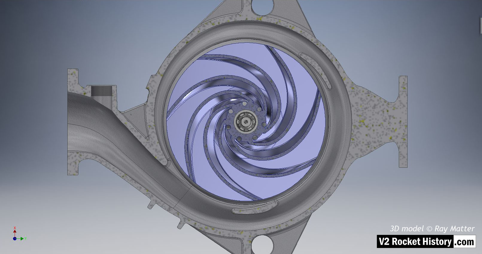
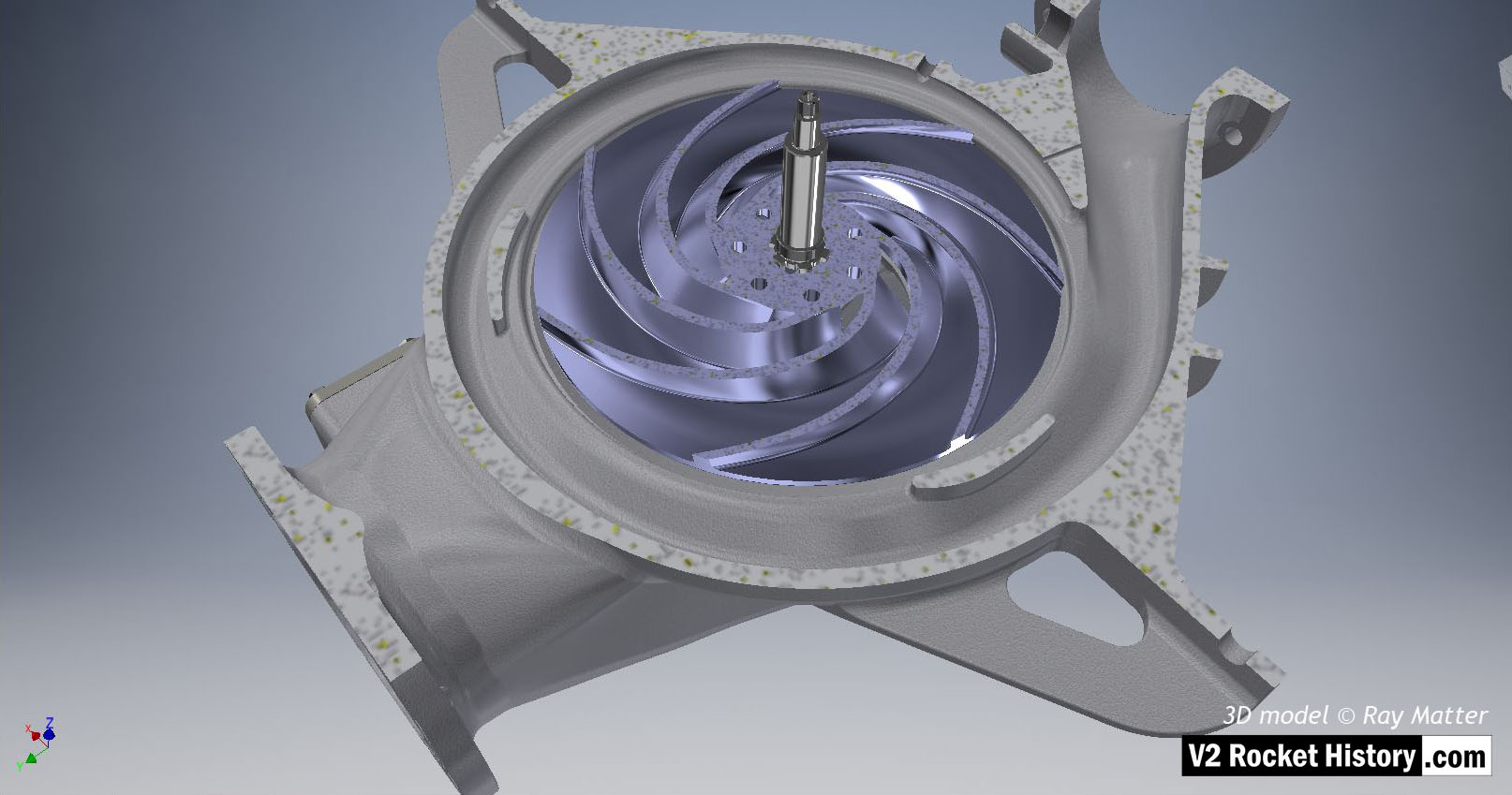
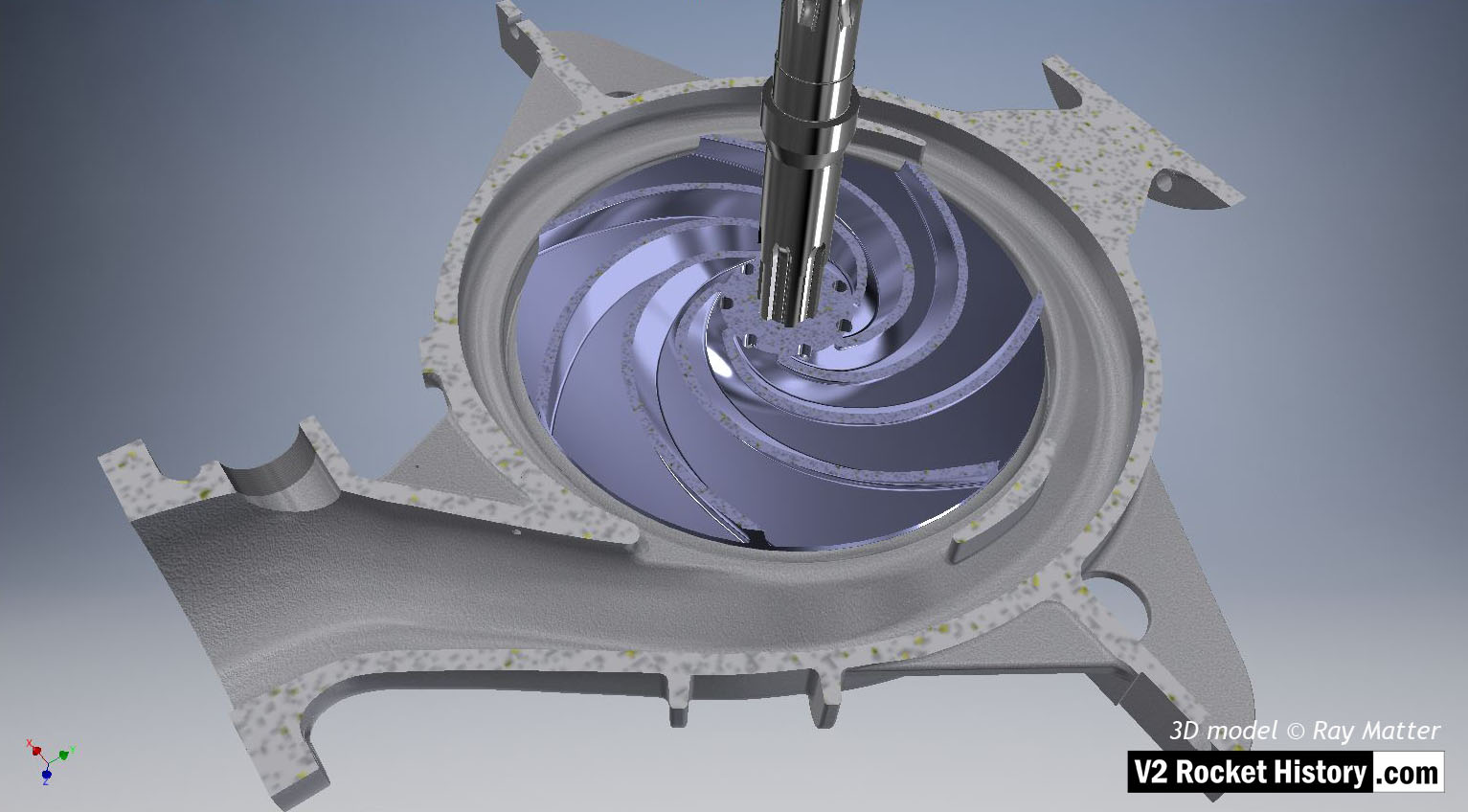
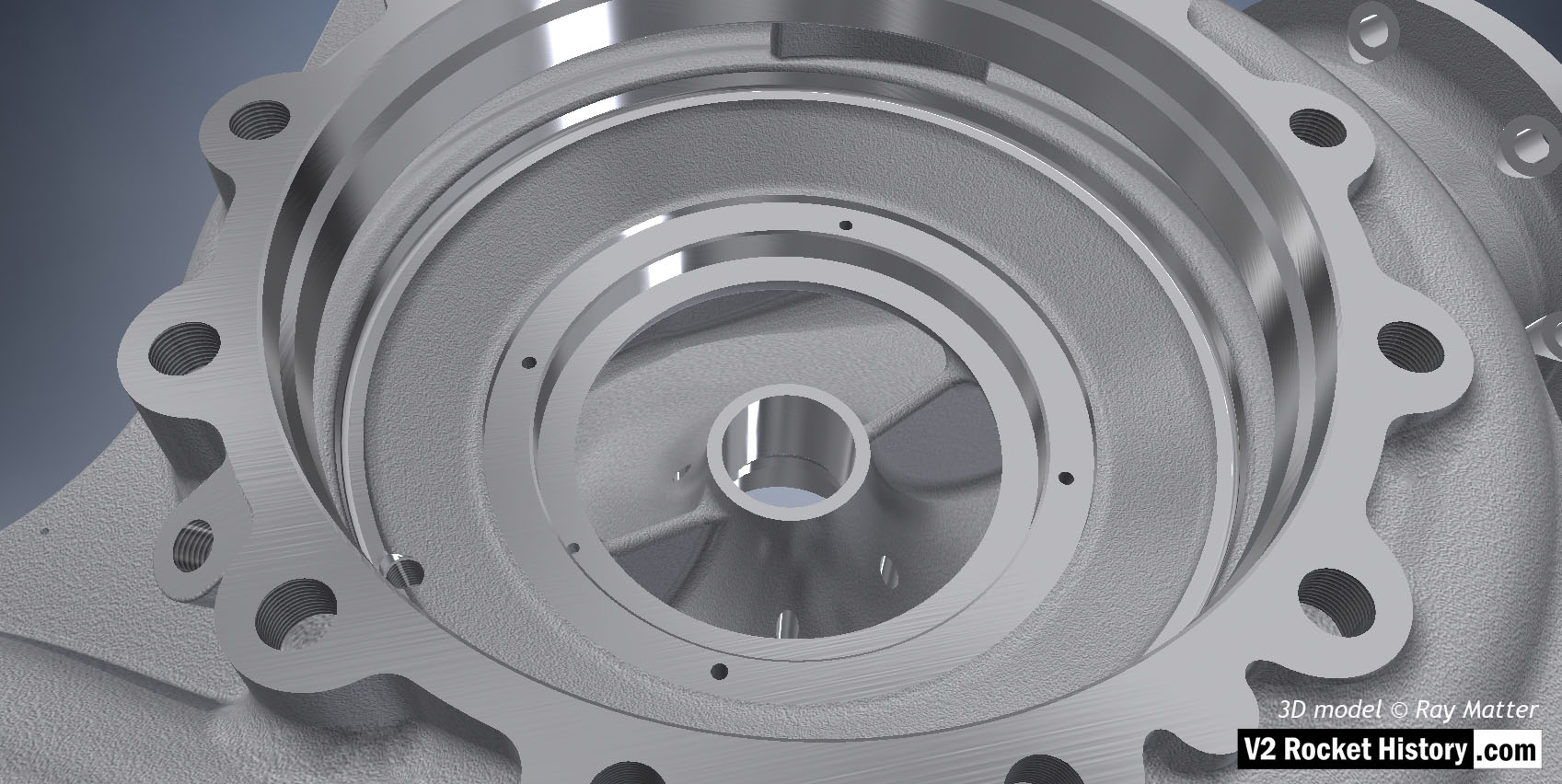
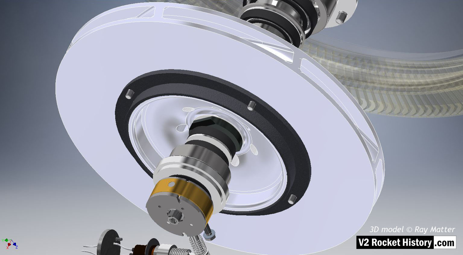
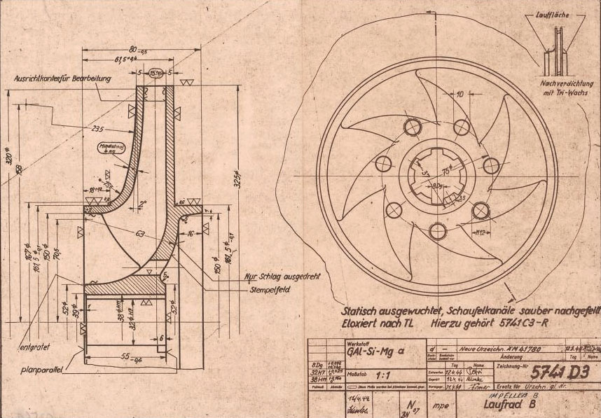
Editor’s comment: 3D interactive model of fuel pump rotor-below: 3D CAD modelling provides the perfect way to visualise the design of the V2 rocket engine parts and Ray Matter’ turbopump model, accurate in every detail and faithful to the original HAP drawings, allows the viewer to see every detail of the original drawings but in the ideal form of a virtual part. The interactive fuel pump impeller shown below is a spectacular example – use mouse (or finger) to move the impeller around and use the mouse roller to zoom in! RJD
B (fuel) pump impeller from mpe drawing number 5741 D3. Object and image copyright Ray Matter
The historical drawings
Other than their being scattered about, with sometimes limited continuity in the codes and drawing numbers, the drawings are excellent and a pleasure to transcribe. Such difficulties as the drawing numbers present are not due to any fault of the original draughtsmen but because of the incomplete nature of the current archive – at least that portion of it that is easily accessible on the internet. Everything is there, dimensions, materials, finishes, anti-corrosion treatments, as well as here and there the added insight of hastily hand-written notes that hint at the pressure being felt in the design and drawing offices nearly 80 years ago.
 Pump: 3")
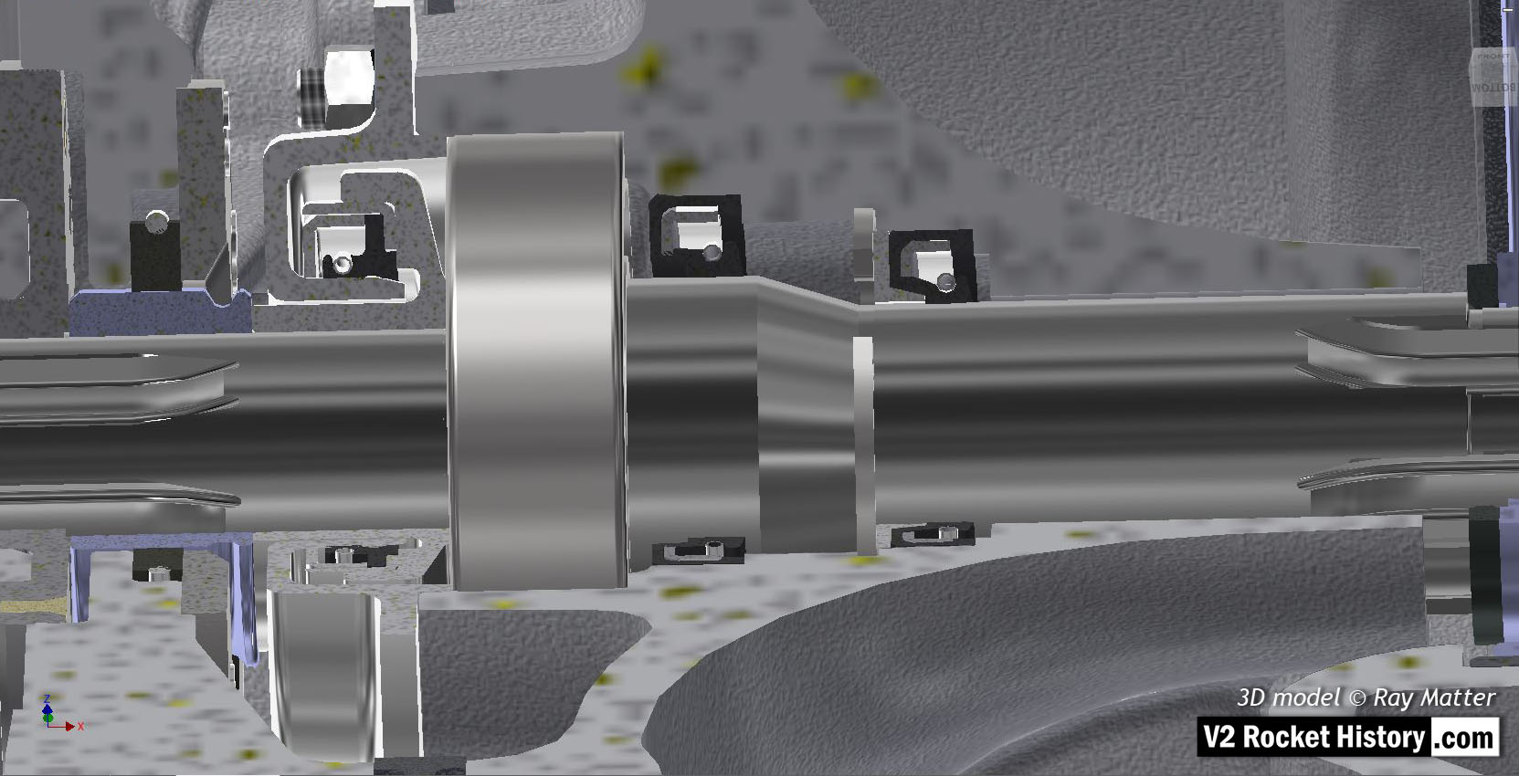
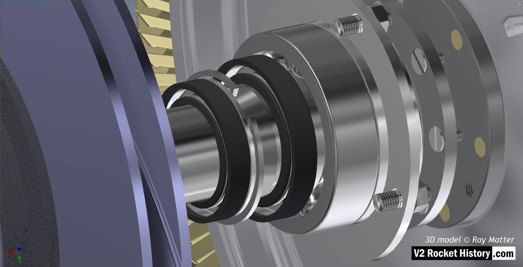
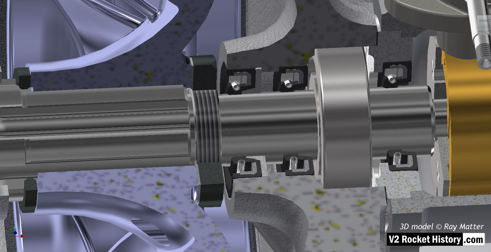
By far, the hardest obstacles to overcome are the unexpected omissions from the archive. It happens that within a hierarchy of related assembly drawings that what at first appears to be complete to every part there may be elements that are not covered in detail on any plan. Only as the work progressed in depth did it become clear that small pieces were missing. I had completed much of the drawing for one of the pumps before I realised that archive documents covering a range of parts related to the packing seals are not currently available in the online annals. It was necessary to reverse engineer the designs from available modern equivalents and use the known dimensions of the cavities that the parts would fill to size them accurately!
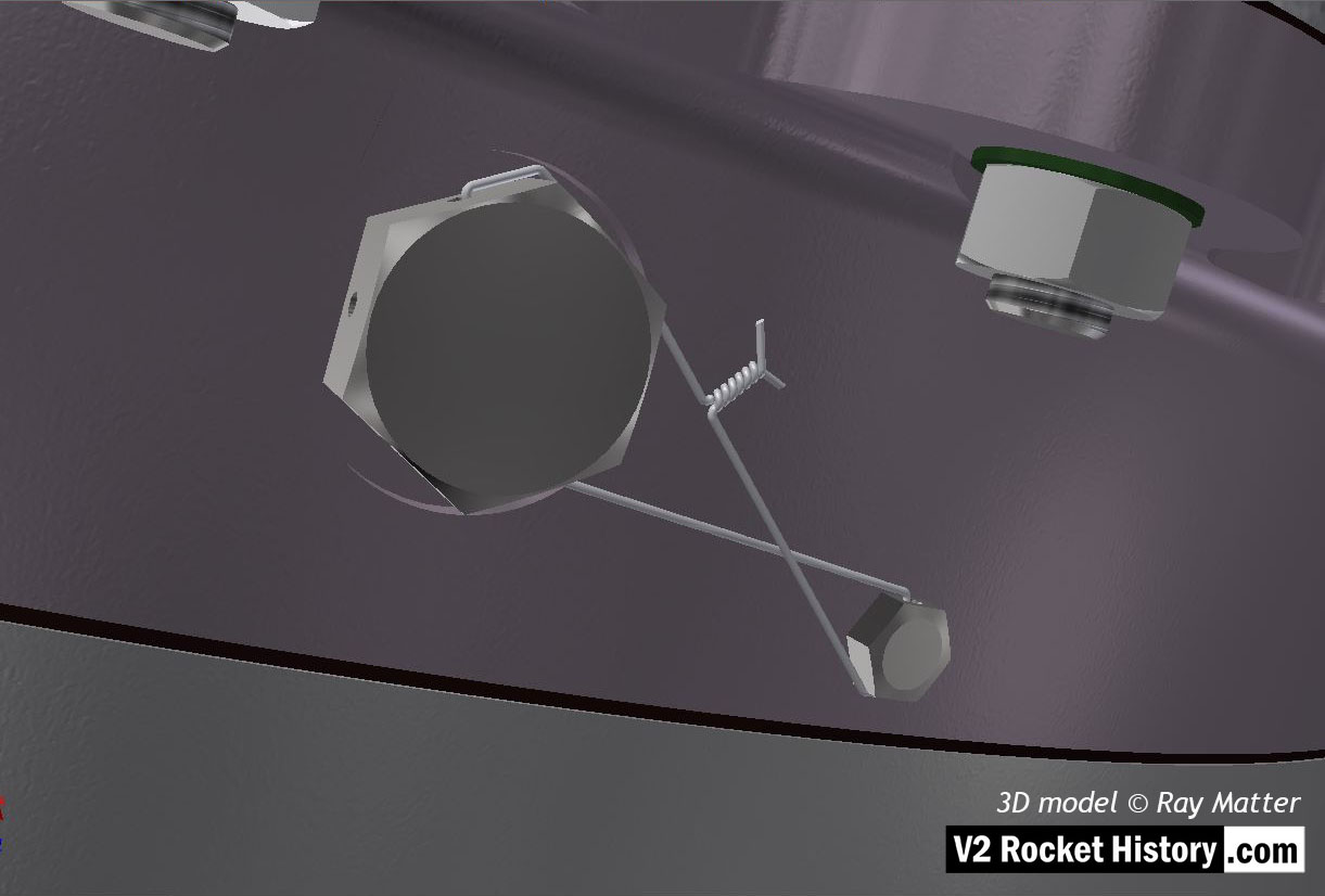
But the parts aren’t always small. It has happened that a reference to a part has sent me off looking for a set of components only to discover that the assembly, though shown completely on some drawings, was not used on the missile.

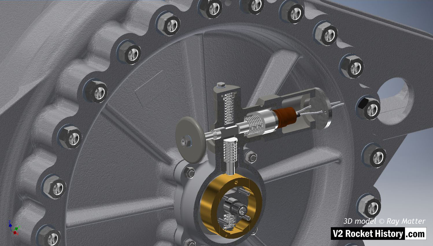
Just such a case occurred last January and caused an interruption to work lasting several days. The issue concerned the tachometer or revolutions counter for the turbopump. The situation was eventually resolved by consulting with Tracey Dungen and Robert Dalby and ascertaining that the tachometer system, although visible on plans up to 1944 was not revised after 1942 and was only used for ground testing of the turbopump and not part of the missile’s onboard equipment – at least not beyond the development stage.

The challenge of taking Inventor to its limits with some of these housings was intriguing. Of course, delving into the minds of the German team’s work has been the greatest interest, and part of the principle reason to look back from what they did is to find out just how they did it.
As time allows in the coming months, I’ll be translating more of the V2 drawing archive and learning more about the challenges faced by the missile’s designers – so keep an eye on these pages or subscribe to the newsletter to see the work progress.
Postscript: In case anyone is curious most of the work is done on a Dell Precision 7910 with Xeon E5-2600 v4 processor running Autodesk Inventor. RM
The image gallery below has all the above pictures in higher resolution, some with additional text, as well as additional pictures not included in this post.