
KSB catalogue from 1880
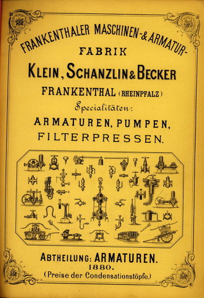
Cover of catalogue published in 1880 showing the KSB product range
Album: Turbopump parts and relics
Categories: Sub-assemblies
Tags:


Cover of catalogue published in 1880 showing the KSB product range
Album: Turbopump parts and relics
Categories: Sub-assemblies
Tags:

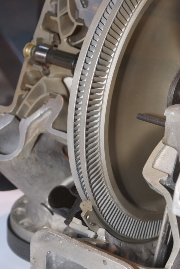
This image shows a cutaway of an A4-V2 turbo-pump. The section reveals the Curtis type 2-stage steam-turbine rotor and you can also see part of the stater inserted between the blades (bottom middle) and the adjacent steam distribution pipe (black open pipe on stater’s immediate left). Top left, a centrifugal pump rotor can be seen – cut through, it shows a multi-splined shaft running through the centre, simple bearing and end-cap.
Album: Turbopump parts and relics
Categories: Sub-assemblies
Tags:

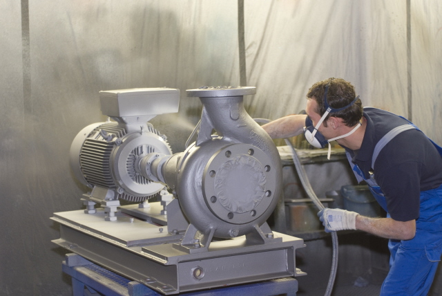
Electric industrial volute case centrifugal pump by Klein Schanzlin & Becker. This image highlights the ‘genetic’similarity and family resemblance between KSB’s current and historical product range and the visible features of the A4-V2 missile Turbo-Pump (TP). Assembly is shown being spray painted.
Album: Turbopump parts and relics
Categories: Sub-assemblies
Tags:

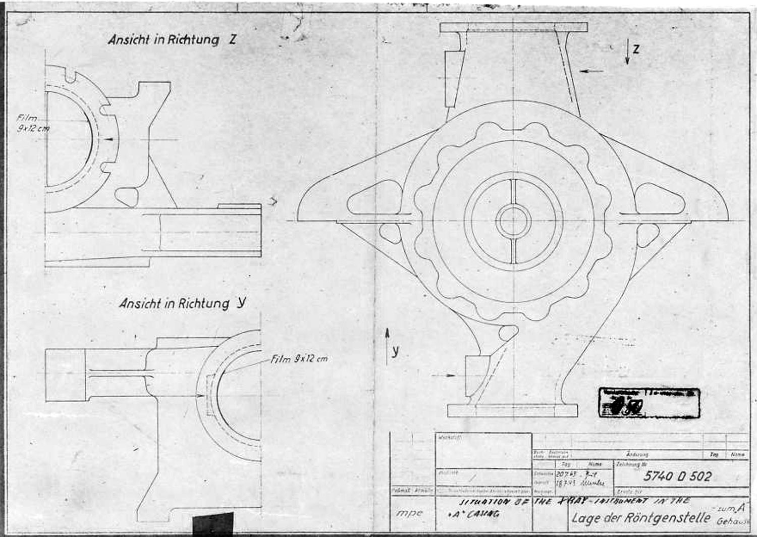
A Stoff (liquid oxygen) pump casing diagram showing stress points that require X ray quality control photography before use. The diagram shows the specific locations where photographic film is to be placed for X-ray analysis.
Album: Turbopump parts and relics
Categories: Sub-assemblies
Tags:

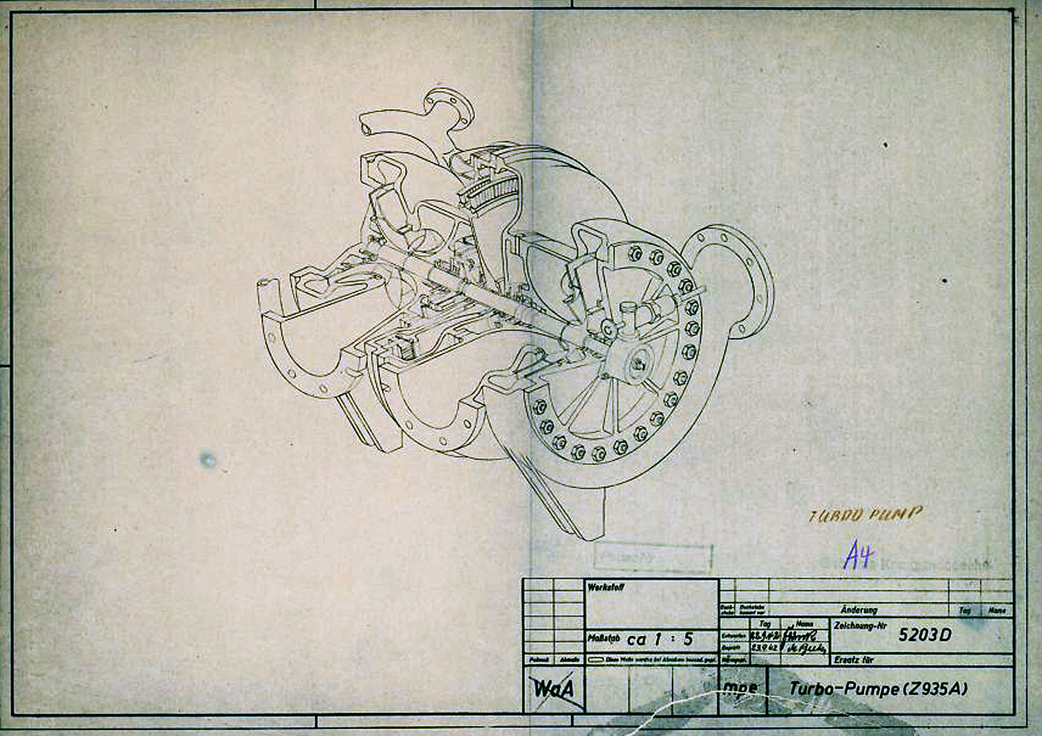
In this diagram the V2 Turbo-pump is shown in a cutaway presentation and rotated 90 degrees counter clockwise. The B stoff (fuel) pump is nearest the viewer – the over-speed device can be seen on the B stoff pump’s case end-plate. The low pressure inlet ports our shown to the left, and high-pressure outlet ports are on the right. The steam distribution manifold can be seen at the furthest point from the viewer – the steam inlet pipe flange can also be seen. The feed pipe from the steam generator attaches to thus flange.
Album: Turbopump parts and relics
Categories: Sub-assemblies
Tags:
Copyright: V2 Rocket History
