Drawing of fuel nozzle Insert 1113E 1939
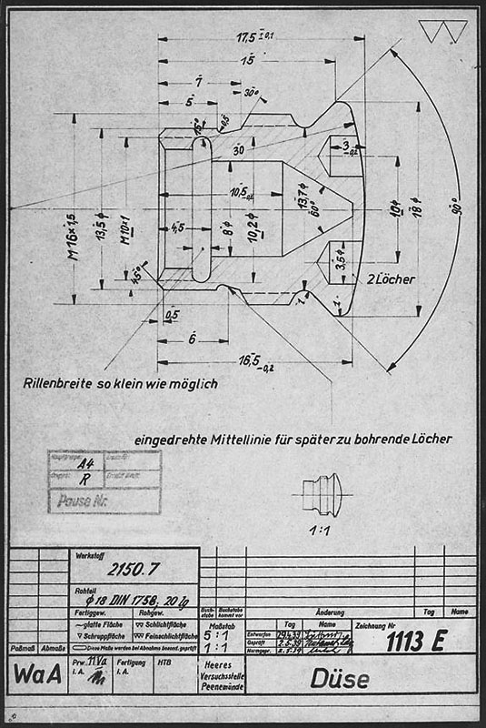
Drawing from the Army Experimental Station Peenemünde dated 1939. The specification describes an insert template that could be used for a range of outlet and inlet orifice sizes. The German text beginning (eingedrehte …) translates as ‘Center-line of screw used for holes to be drilled later’, and the hole dimensions are not specified on this document. HVP drawing number 1113 E, Deutsches Museum München
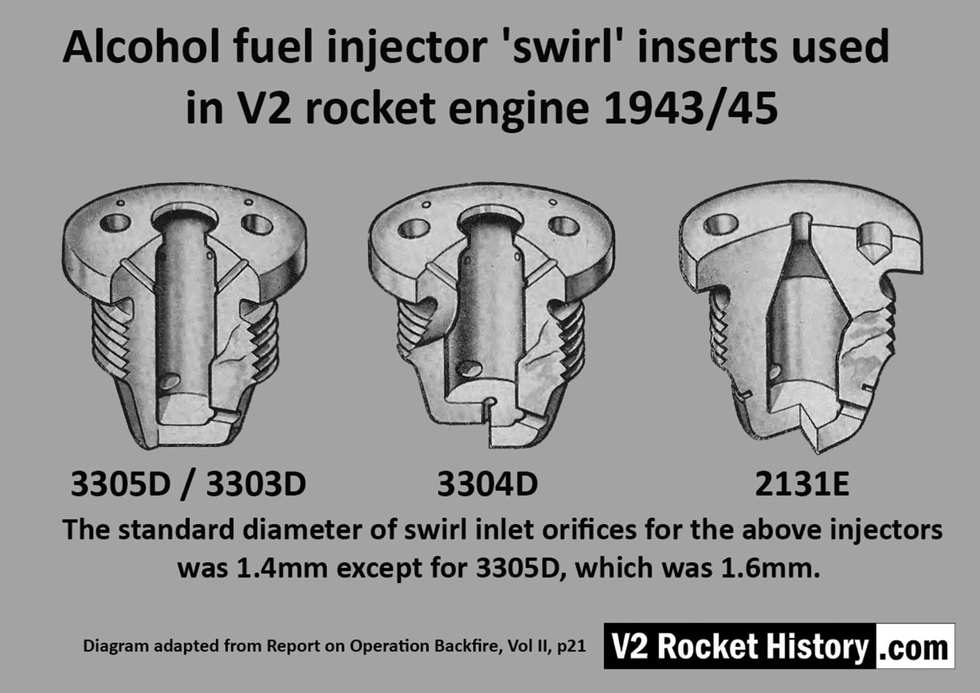
Album: V2 rocket fuel injector inserts
Categories: Combustion Propellant flow
Tags: