For more detailed images see the image gallery at the bottom of this post
The eighteen pot injector head.
This is the first image blog from Alexsander Savochkin in what we hope will become an expanding resource for those wishing to find out more about the design and construction of the A4/V2 missile. The precise 3D CAD model imagery is based exclusively on original drawings produced in Germany from 1940 to 1945. When enough material has been uploaded we will create a fixed menu item called ‘Anatomy of the V2‘ where we hope to be able to offer coverage of the entire missile in detailed 3D models like the ones shown here – Robert J. Dalby, editor in chief, V2 Rocket History.com
View of injector head showing liquid propellant (LOX and fuel) diffuser cups and head fuel valve seating ring at centre, (see other images for insert and position nomenclature). Visible immediately below the valve seat are the large connecting holes that allow fuel to flow from the inlet manifold and cooling jacket to the injector space (some brass injector inserts can be seen through the holes) after the head fuel valve is released to be opened by the turbo-pump supply pressure. The four veil cooling inlet connectors are well shown as are two of the outlet connection holes immediately above them. 3D model by Alexander SavochkinA close-up view of the head fuel valve mounting flange (showing 12 fastener holes). Visible immediately below the top flange are the large connecting holes that allow fuel to flow from the inlet manifold and cooling jacket to the injector space (some brass injector inserts can be seen through the holes) after the head fuel valve is released to be opened by the turbo-pump supply pressure.Inverted view of injector head showing liquid propellant (LOX and fuel) diffuser cups, (see other images for insert and position nomenclature). Of note in this image are the pointing angles of the cups, positioned on a parabolic section to focus the propellant nebular stream into the central axis of the combustion space. Also of note are the large areas between each cup NOT employed in the injection process leading to structured propellant mixing as opposed to even homogeneous mixing. The four veil cooling inlet connectors are well shown. 3D model by Alexander SavochkinUnderside view of injector head showing liquid propellant (LOX and fuel) diffuser cups, (see other images for insert and position nomenclature). Of note in this image are the pointing angles of the cups, positioned on a parabolic section to focus the propellant nebular stream into the central axis of the combustion space. Also of note are the large areas between each cup NOT employed in the injection process – initiating \’clumpy\’ and uneven propellant mixing initially below the injector face but also carried forward into the combustion space. The LOX spray head is shown in the centre of each cup. 3D model by Alexander SavochkinHere the 18-pot head model has been cut away to show the fuel cooling and fuel delivery spaces. the cooling jacket layer can be seen in the lowermost area of the head – below the centrally positioned fuel valve seat, between each cup at the lowest point, and running down toward the first set of veil cooling pores and the topmost coolant distributor ring. Note that the veil cooling system does not communicate with the regenerative cooling jacket and has its own feed pipes drawing fuel from the head injector space and not the cooling space. Visible immediately above the valve seat are the large connecting holes that allow fuel to flow from the inlet manifold and cooling jacket to the injector space after the head fuel valve is released to be opened by the turbo-pump supply pressure. 3D model by Alexander SavochkinClose-up detail showing independent pathway for fuel passing into injector head and fuel passed down from the head to be used for veil cooling system. Fig. A shows vertical passages for overall fuel feed to the head and Fig.B shows horizontal pathway for veil coolant fed from the head via the veil coolant distributor ring or manifold. 3D model by Alexander SavochkinLiquid propellant (LOX and fuel) diffuser cup, showing three rings or echelons (A, D,& E) of brass injector inserts as well as two rows of drilled fuel feed holes. The LOX spray head is shown in the centre. Note the simple ‘shower head or watering can’ design of the LOX diffuser. A sealing washer can be seen fitted between the LOX diffuser and the steel cup. 3D model by Alexander SavochkinView of the top of the injector head, with outer cups and pressed steel capping piece removed, showing, propellant diffuser inner cores with injector inserts and LOX supply pipe connection thread. The LOX spray head can be seen inside the LOX pipe connector. The swirl caps of fuel injector inserts in positions A, D,& E can be seen clearly on the outside of the cores and the two rows of drilled fuel feed holes are also well shown. 3D model by Alexander SavochkinGeneral view of the propellant diffuser cup inner core. The swirl caps of fuel injector inserts in positions A, D,& E can be seen clearly on the outside of the core as well as the central holes in the 3304D (red) inserts. The two rows of drilled fuel feed holes are also well shown. 3D model by Alexander Savochkin
Click the above video to see an animation of the diffuser cup inner core (the animation may take a few seconds to show at maximum resolution).
This image shows a burner cup from outer Ring I of the injector head and the cutaway shows injector insert echelon A, D, & E as well as two rows of drilled feed holes. Four fuel injector insert types can be seen: Top, A = 2131E, lower D, = 3303D (white), lowest E, = 3304D (red), and E, = 3305D (blue). 3D model by Alexander SavochkinCutaway showing echelon A with 2-part 2131E fuel injector inserts at the top of a propellant diffuser cup. Note the close proximity of the injector inserts to the simple ‘watering can’ type LOX spray head. One row of drilled fuel feed holes can be seen below the inserts. 3D model by Alexander SavochkinThis images shows a cutaway of a burner cup from outer Ring I of the injector head and shows injector insert echelon D, & E as well as one row of drilled feed holes. Three fuel injector insert types can be seen: Top D, = 3303D (white), lower E, = 3304D (red), and E, = 3305D (blue). 3D model by Alexander SavochkinOne of the 18 liquid propellants (LOX and fuel) diffuser cups, showing three rows or echelons (A, D,& E) of brass fuel injector inserts as well as two rows of drilled fuel feed holes. The LOX spray head is shown in the centre. 3D model by Alexander SavochkinExploded view showing some of the 1100 parts required for the complicated 18-pot injector head of the V2 25-ton thrust rocket engine. 3D model by Alexander Savochkin
The image gallery below has all the above pictures in higher resolution, some with additional text, as well as additional pictures not included in this post.
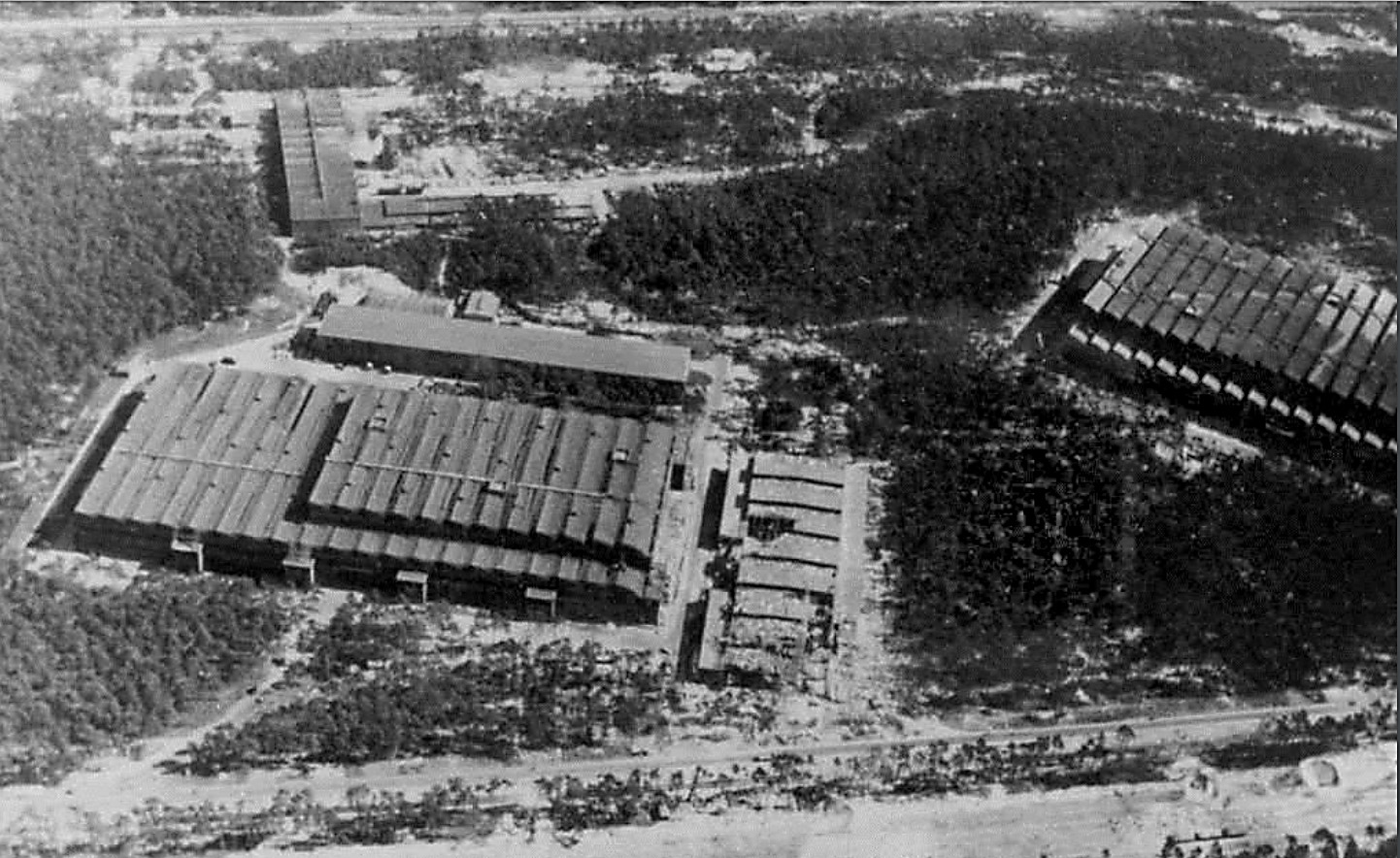
IW and F1 on 19th August 1943
IW and F1 on 19th August 1943
Photo showing Werk Süd with IW on the left and F1 on the right taken on 19th August 1943. The photo shows only light damage to the main halls, although F1 was actually hit at least 11 times, and hits to the separate single storey workshops to the right of the IW hall. The long storage (oil and paint?) shed above IW and the woodworking shop at the top of the picture appear undamaged. Anti-aircraft platforms (at least 3) can be seen on the roof of IW but that seem to be empty of guns. F1 shows two AAA platforms (there was at least 3 at this stage and maybe more) and they may have guns installed. General W. Dornberger mentions defensive AA artillery fire from the from the roof of F1 in his 1952 book V2 (1954 in English).
The remains of the a rail and truck loading stage located in the long oil storage shed adjacent to the IW repair and maintenance hall (IW R&MH) are substantial and have intact steadying chains along the south edge of the platform. There are access steps to the west and east ends (east shown). This loading stage was originally furnished with a wooden platform.
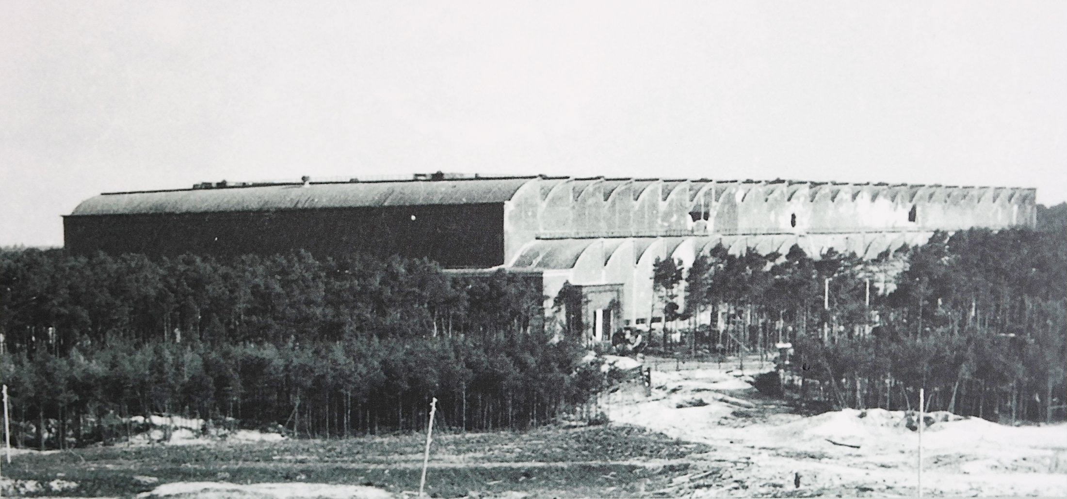
Fertigungshalle Eins (F1) after the RAF raid of 1943
Fertigungshalle Eins (F1) after the RAF raid of 1943
A rare photo of the giant F1 production hall taken not long after the RAF raid of 17/18th August 1943. F1 was a forced labour camp with at least 600 prisoners living within the factory and at least eleven were killed in the raid. Parts of the electrified barbed wire fence can be seen close to the factory building, in the clearing in the middle of the photo. Two anti aircraft gun emplacements can be seen on the roof at the front of the building. Holes in the side walls of the upper vaults can be seen as well as the damage to lower vaults 9 and 10 (counting from left) from a direct hit in this region. Also of note are the numerous guy ropes, attached to the upper roof of the front of the building - and running down towards the trees, that are just visible in the photo. These may be supports for camouflage netting that was in the process of being fitted (by prisoner gangs) just before the raid. The work was never completed.
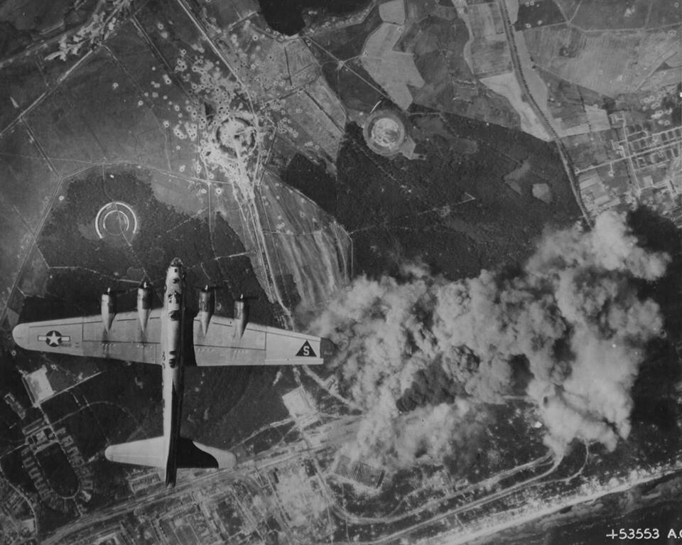
Peenemünde: Werk Sud attacked by US bombers August 1944
Peenemünde: Werk Sud attacked by US bombers August 1944
Peenemünde: Werk Sud attacked by US bombers August 1944 in a daring daylight raid. The two large halls F1 and IW in the lower middle of the photo are under direct attack and smoke can be seen originating from both buildings. Although the August 1944 raids did little to interrupt the volume manufacture of the V2, as virtually all manufacturing and assembly of the missile had moved to central Germany, the raids did bring to an almost complete halt the last small amount of manufacturing work still competed in the giant halls of Werk Sud.
A tutor in computer-aided design at Moscow State Technical University, Alexander Savochkin says he finds relaxation in transcribing 75-year-old missile plans into modern 3D CAD models. He lives with his very patient wife in the leafy suburbs of Moscow.