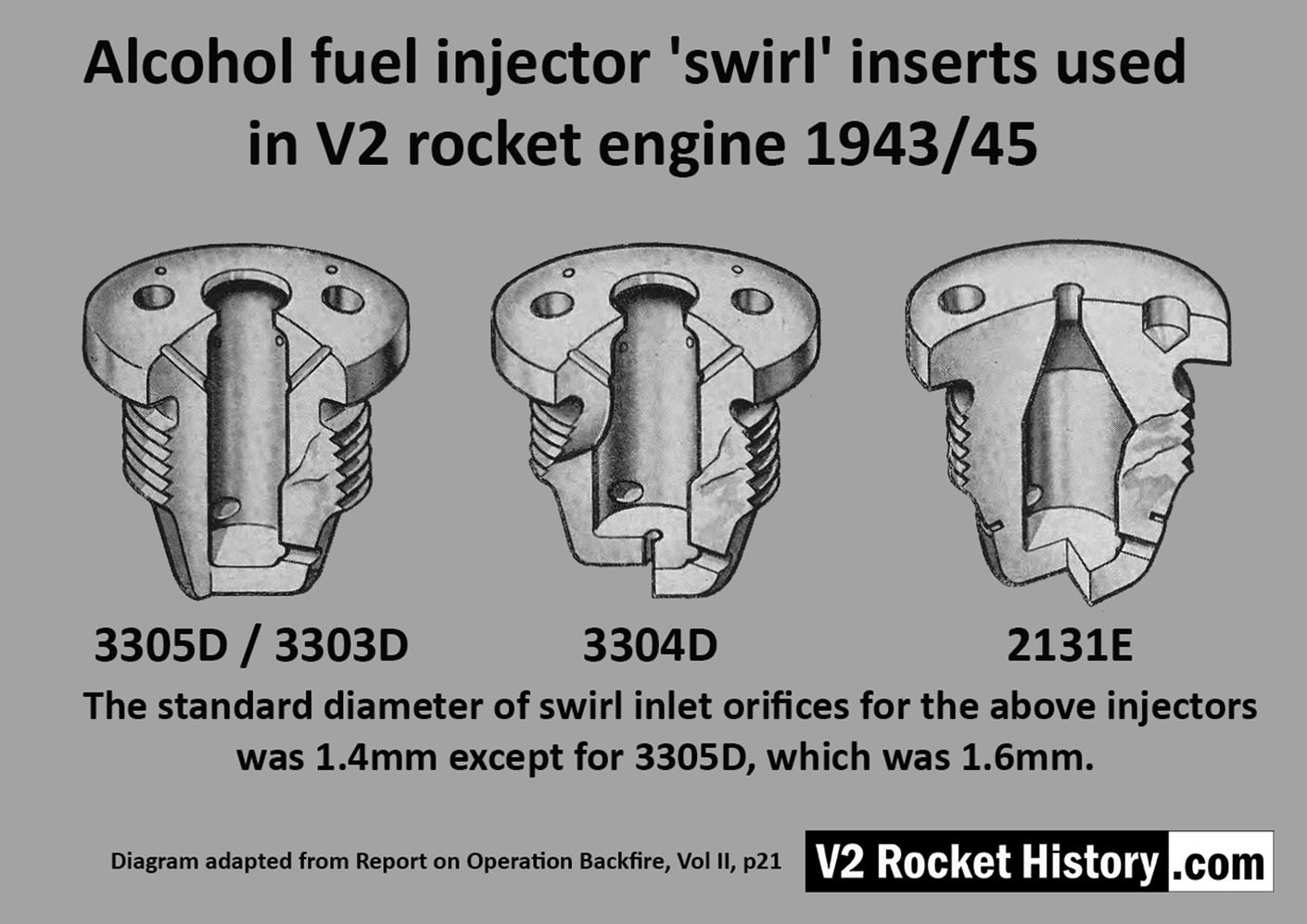
Diagram showing cut-away presentations of the settled configuration of standard four 'swirl' inserts used in the V2 rocket engine's 18-pot head from 1943 until the end of the war. The inserts are shown with their drawing code identification. All of the insert types used in the injector head are shown, however there were additional screw-in type fuel supply inserts, used to provide a fuel cooling balance function, located radially in the lower part of the combustion cavity.


Be the first to comment