Injector insert set detail with drawing codes

Injector insert set detail with drawing codes

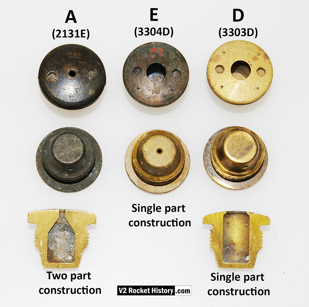
Fuel injector inserts for production series 18-pot injector head. The top row shows the injector face, second row shoes the same types from the rear. The lowermost insert have been halved to reveal the cavity shape, orifice edge, inlet and cooling apertures. Note that the insert in column A, 2131E, is two piece construction, and pressed together for assembly (see additional photo). On test, the parts had to remain together under a separation force of 300kg.

About Robert J Dalby 9 Articles
Born Ilford, London, the last V2 missile attack on England missing him by 25 miles and 14 years. Read philosophy for nearly a decade - and so naturally pursued a career in astronomy optics and engineering design. Career highpoints: co-inventor of the LRGB imaging method now in use by serious amateur and professional astronomers worldwide. Responsible for the design of a host of devices used in the field of telescopic astronomy. And once ate nine pancakes without passing out. Spends too much time in shadowy corners fiddling with old missile parts to be socially acceptable, but was once described as a geek's idea of a geek. [email protected]

Be the first to comment

Leave a Reply

Your email address will not be published.


*