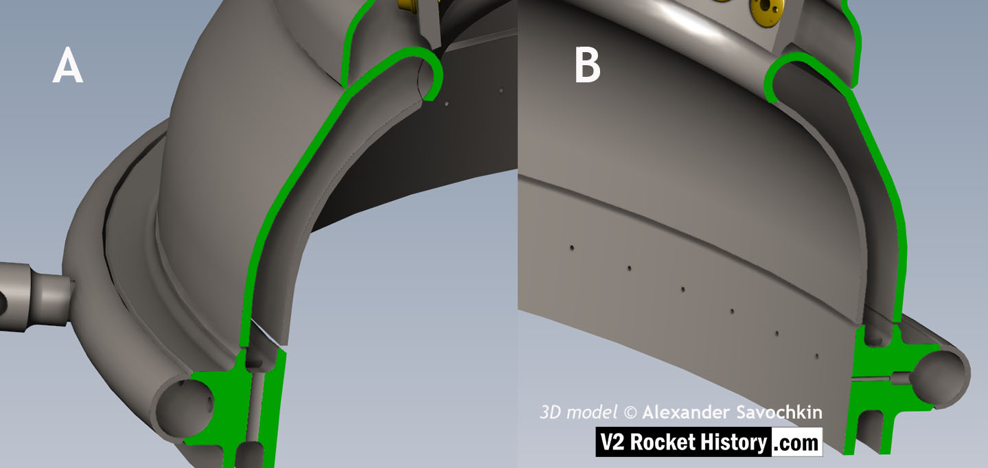
18-pot Upper Veil Manifold detail

18-pot Upper Veil Manifold detail

Close-up detail showing independent pathway for fuel passing into injector head and fuel passed down from the head to be used for veil cooling system. Fig. A shows vertical passages for overall fuel feed to the head and Fig.B shows horizontal pathway for veil coolant fed from the head via the veil coolant distributor ring or manifold. 3D model by Alexander Savochkin

About V2 Rocket History 10 Articles
At V2 Rocket History our aim is to investigate the history and technology of the A4-V2 missile, and share the results in the most accessible and engaging way possible. Our general approach is to highlight the engineering and industrial aspects of the subject.

Be the first to comment

Leave a Reply

Your email address will not be published.


*