No Picture

Fuel Injector insert showing aperture details

Fuel Injector insert showing aperture details

Standard fuel injector inserts for production series 18-pot injector head. Insert 1 (3304D/3305D) shows four thin wires demonstrating the angles of all four ‘cooling’ pores. Insert 2 (3305D/2131E) has two 1.3mm twist drill showing the edge bores for the gyroscopic swirl inlets. Insert 3 (3305D) shows another view of the cooling pore angle and origin. V2RH image

Album: Testing fuel injectors

Tags: #Test procedures

No Picture

V2 Fuel Injector 2131E

V2 Fuel Injector 2131E

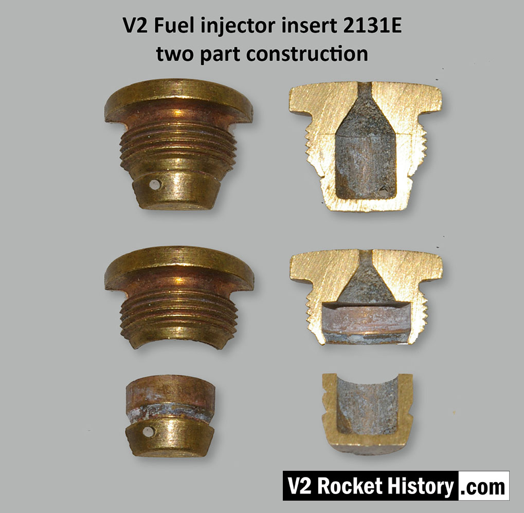
V2 Fuel Injector insert: part code 2131E from injector pot echelon A (nearest to LOX spray head). The push-together two part construction of the insert is shown here. The two parts were pushed together in a specially shaped tool set that compressed the thin skirt on the female part into a recess cut into the male part. The failure test for this component required that the mated parts resist a separating force of 300kg. The two part design was dictated by the small size of the 2mm exit orifice and the funnel shaped introduction to the exit orifice. In the case of the other three standard inserts, the large 6mm exit orifice allowed a sub 6mm milling cutter, with a thin support shaft and a top chamfer, to be used in such a way that the area below the exit orifice could be undercut to create an injector cavity with a diameter larger than the 6mm entry point.

Album: Testing fuel injectors

Tags: #Test procedures

No Picture

V2 fuel injector Insert test rig

V2 fuel injector Insert test rig

Single nozzle insert test rig used by V2 Rocket History to test spray shape and volume at supply pressures consistent with fuel pressures specified for the injector head of summer 1944. The test system features an adjustable pressure regulator and fluid pressure gauge. For test purposes the device was simply connected to a relatively high pressure mains water supply. And although water does not have the same viscosity of the 75% Ethenol to 25% water mix of the V2’s fuel it was considered close enough by the German technicians, who regularly used plain water as a substitute when testing issues related to furl flow rather than combustion. A 2131E fuel injector insert is shown installed in the holder at the front of the rig, but as the thread was the same on all inserts the nozzle can be changed for other models easily with aid of a pin spanner. See video for a demonstration of this simple test system.

Album: Testing fuel injectors

Tags: #Test procedures