No Picture

V2 rocket fuel and LOX injector pot

V2 rocket fuel and LOX injector pot

Cutaway section of fuel and liquid oxygen (LOX) injector pot. The exhibit shows the bell shaped thick inner wall of the burner with three tiers of fuel injector inserts (A,D, and E). The central copper alloy LOX spray injector is also well displayed in this image. The thin steel outer shell of the burner cup is shown and affords a good view of the head cavity that supplies fuel to the injector inserts – one A type injector is shown party cut through on the right, its rear portion showing inside the fuel cavity. V2RH image

Album: V2 rocket fuel injector inserts

Categories: Combustion V2 Missile relics

Tags: #Combustion and injection #Propellent injector system

No Picture

Section of fuel and liquid oxygen (LOX) injector pot

Section of fuel and liquid oxygen (LOX) injector pot

Cutaway section of fuel and liquid oxygen (LOX) injector pot. The exhibit shows the bell shaped thick inner wall of the burner with three tiers of fuel injector inserts (A,D, and E). As well as the two rows of plain drilled apertures B and C. The central copper alloy LOX spray injector is also well displayed in this image and shows the three letter armament code of the manufacturer (elr = H.K. Rudolf, Pilsen) and the 1943 date of manufacture on one face of the hex nut. Note the close proximity of the tier A injector inserts to the LOX injector. The spary from these injectors plays directly onto the lower section of the LOX spray head. This section of the burner cap had the lowest temperature and as a result tier A insert did nor require cooling pres. See associated picture. V2RH image

Album: V2 rocket fuel injector inserts

Categories: Combustion

Tags: #Combustion and injection #Propellent injector system

No Picture

Fuel Injector insert showing aperture details

Fuel Injector insert showing aperture details

Standard fuel injector inserts for production series 18-pot injector head. Insert 1 (3304D/3305D) shows four thin wires demonstrating the angles of all four ‘cooling’ pores. Insert 2 (3305D/2131E) has two 1.3mm twist drill showing the edge bores for the gyroscopic swirl inlets. Insert 3 (3305D) shows another view of the cooling pore angle and origin. V2RH image

Album: V2 rocket fuel injector inserts

Categories: Combustion

Tags: #Combustion and injection #Propellent injector system

No Picture

Fuel injector specifications for 25 Ton 18-pot engine

Fuel injector specifications for 25 Ton 18-pot engine

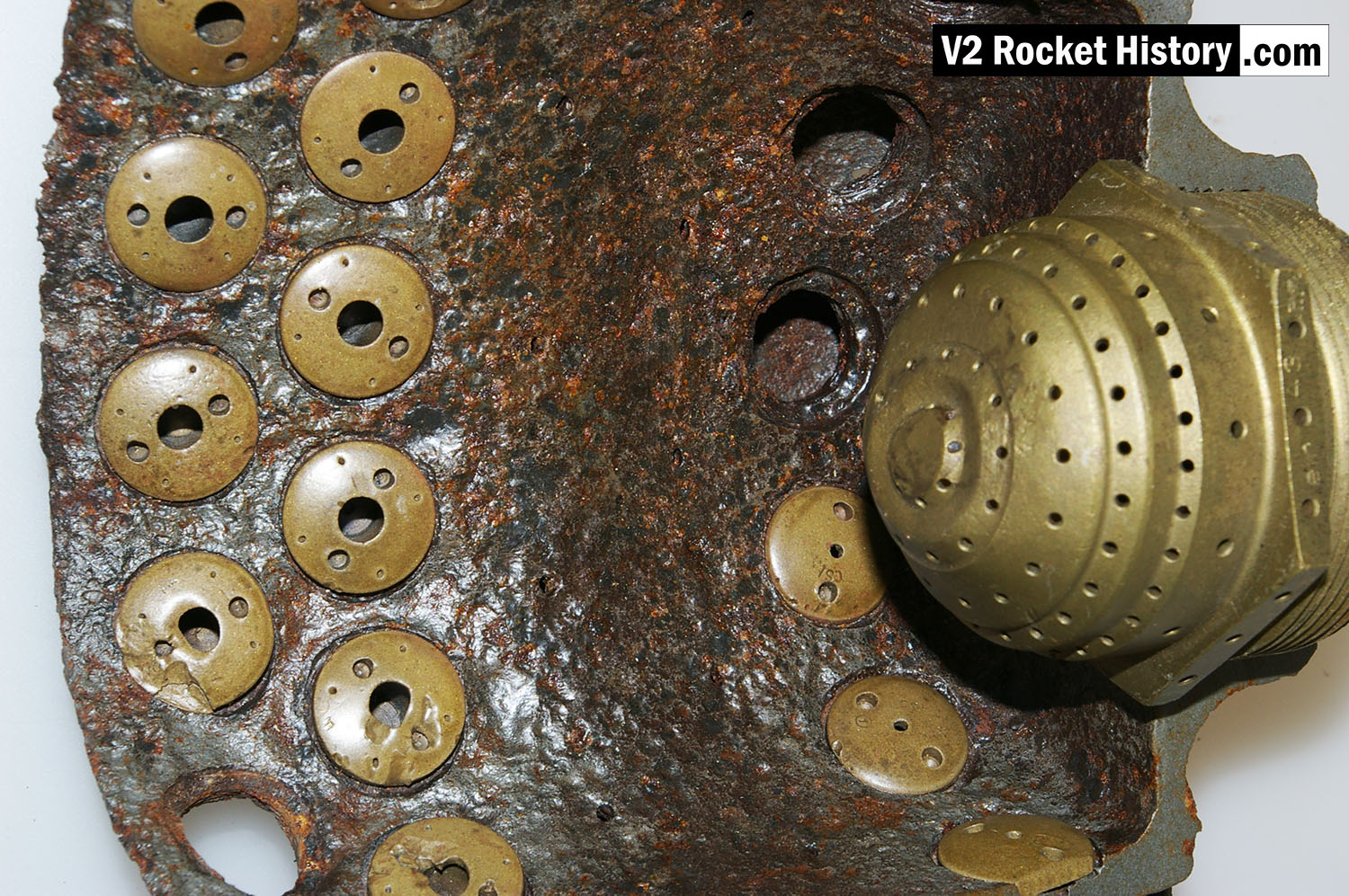
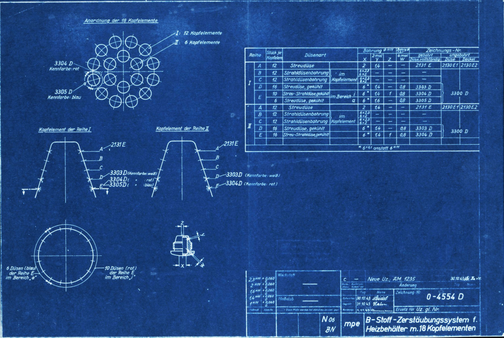
Specification for fuel injector inserts showing orifice size, type, and A to E echelon position. Peenemünde document dated 30th October 1943. Of note on this document is the combination of high and low volume  injector inserts (3304D and 3305D) in the echelon E position of the 12 cups comprising outer ring I. It shows that each cup or pot on this outer ring had 16 inserts at the lowermost position E with 12 of the inserts with three inlet apertures (3305D) and 6 with only two inlet apertures (3304D being lower flow volume) positioned in the segment covering 165 degrees and closest to the outside edge of the head. HAP11 (Heimat-Artillerie-Park 11, AKA armament code: mpe), drawing number 4554D, Deutsches Museum München

Album: V2 rocket fuel injector inserts

Categories: Combustion

Tags: #Combustion and injection #Propellent injector system #V2 Technical Drawings