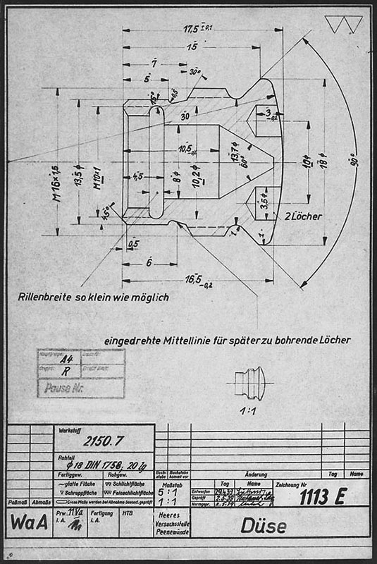
V2 Rocket standard screw-fit fuel Injector Insert 3304D 1944
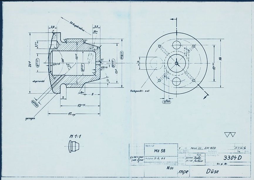
HAP11 drawing of standard 3304D fuel injector screw insert. showing details of primary swirl cavity and orrifice and all additional apertures including the four small cooling pores. HAP11 (Heimat-Artillerie-Park 11, AKA armament code: mpe), drawing number 4554D, Deutsches Museum München
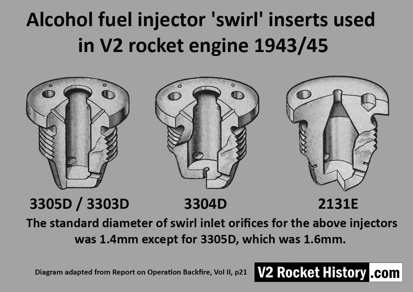
Album: V2 rocket fuel injector inserts
Categories: Combustion Propellant flow
Tags: