No Picture

V2 rocket fuel injector inserts
V2 rocket fuel injector inserts

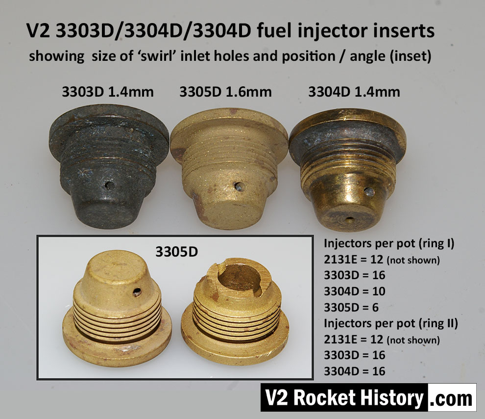
V2 fuel injector inserts 3303D, 3304D, and 3305D for injector pot echelons D and E. Photo shows swirl inlet aperture size and position.The total number of each insert type is shown, each of the 18 pots carried a total of 44 inserts. An additional 24 feed holes were drilled into the burner cup, occupying two rows B and C having 12 holes each. V2RH image

Album: V2 rocket fuel injector inserts

Categories: Combustion

Tags: #Combustion and injection #Propellent injector system #V2 Missile relics

No Picture

V2 fuel injector Insert test rig

V2 fuel injector Insert test rig

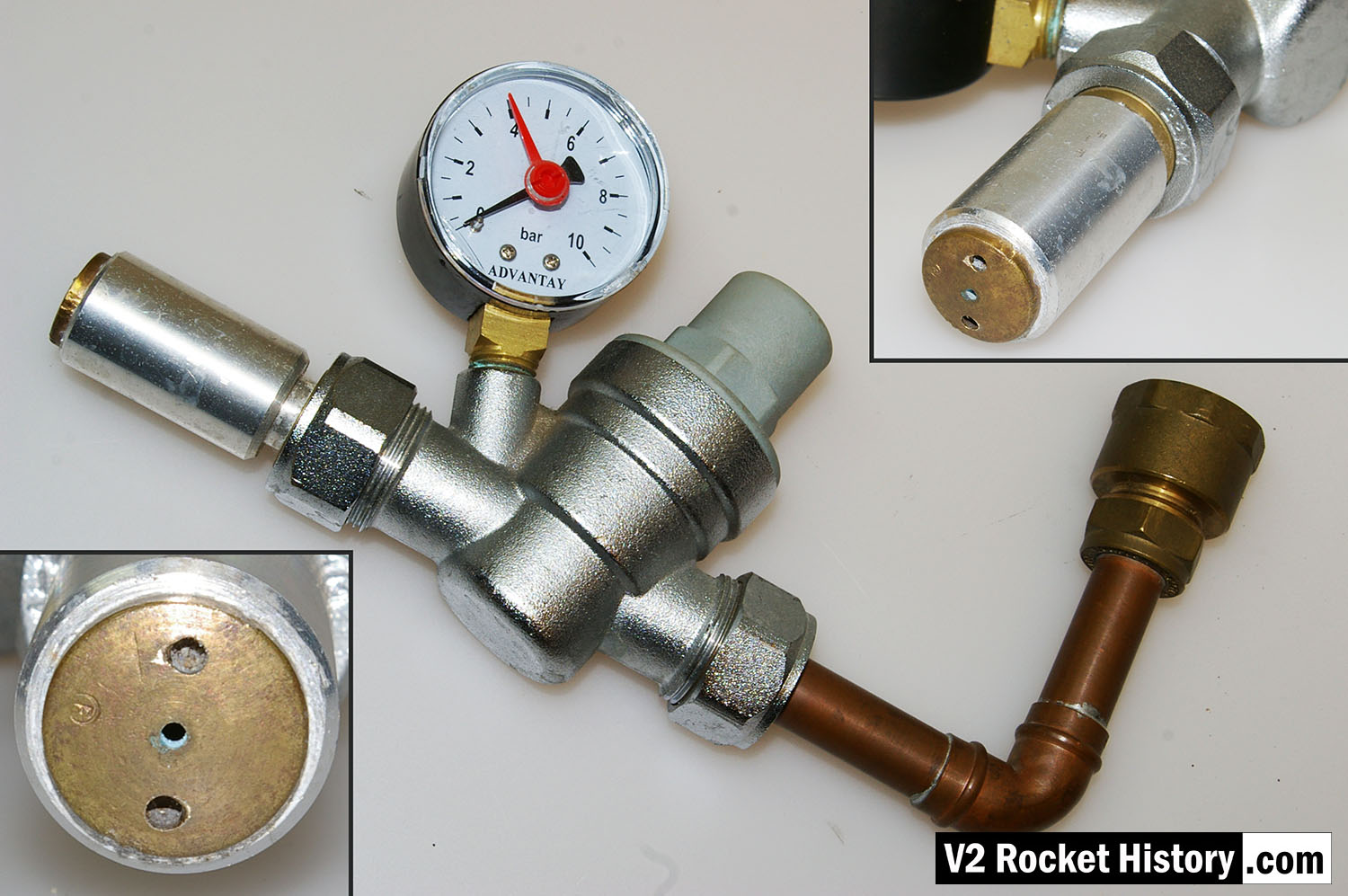
Single nozzle insert test rig used by V2 Rocket History to test spray shape and volume at supply pressures consistent with fuel pressures specified for the injector head of summer 1944. The test system features an adjustable pressure regulator and fluid pressure gauge. For test purposes the device was simply connected to a relatively high pressure mains water supply. And although water does not have the same viscosity of the 75% Ethenol to 25% water mix of the V2’s fuel it was considered close enough by the German technicians, who regularly used plain water as a substitute when testing issues related to furl flow rather than combustion. A 2131E fuel injector insert is shown installed in the holder at the front of the rig, but as the thread was the same on all inserts the nozzle can be changed for other models easily with aid of a pin spanner. See video for a demonstration of this simple test system.

Album: V2 rocket fuel injector inserts

Categories: Combustion Propellant flow

Tags: #Combustion and injection #Propellent injector system

No Picture

Injector insert set detail with drawing codes

Injector insert set detail with drawing codes

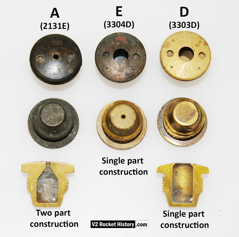
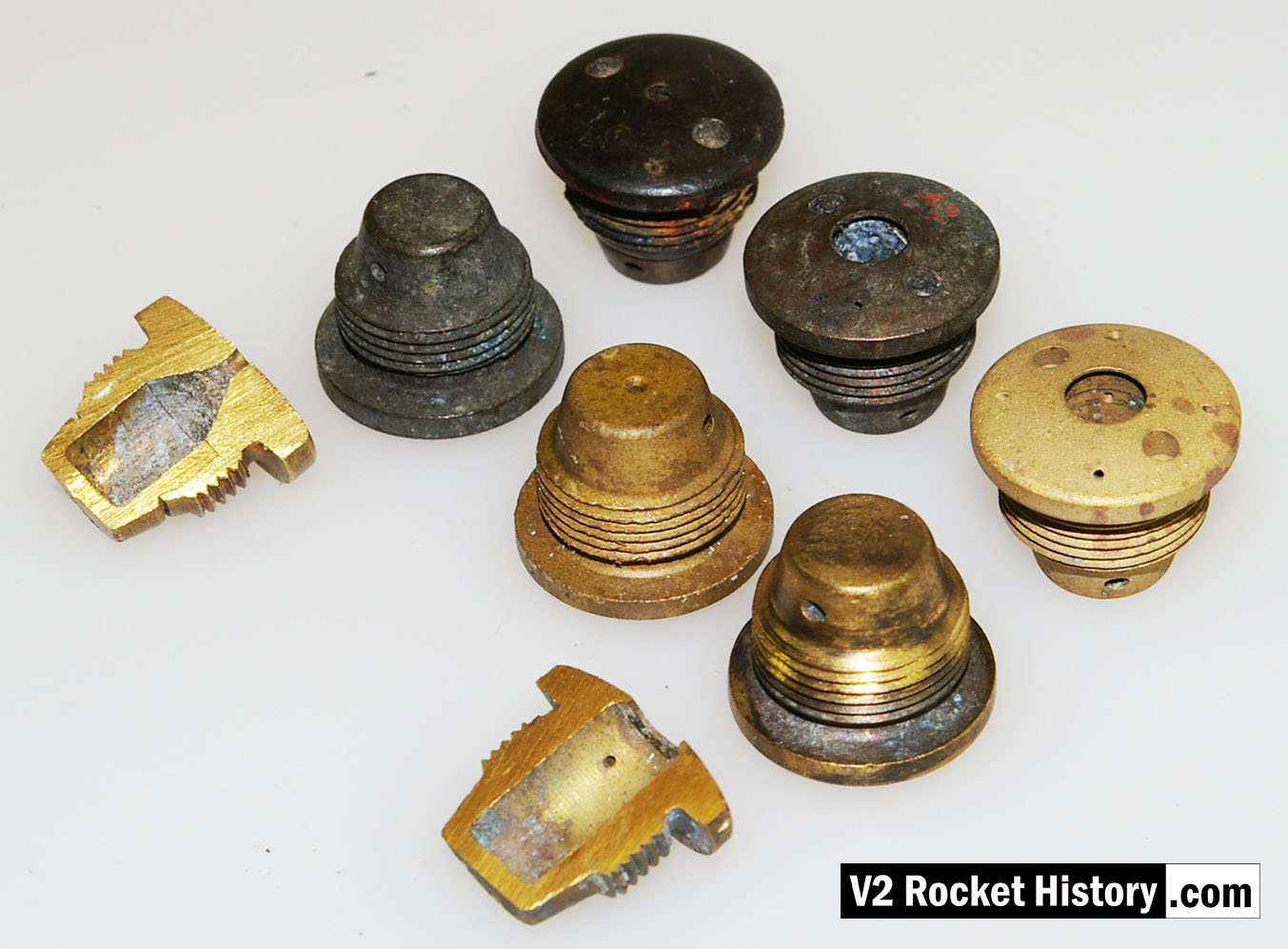
Fuel injector inserts for production series 18-pot injector head. The top row shows the injector face, second row shoes the same types from the rear. The lowermost insert have been halved to reveal the cavity shape, orifice edge, inlet and cooling apertures. Note that the insert in column A, 2131E, is two piece construction, and pressed together for assembly (see additional photo). On test, the parts had to remain together under a separation force of 300kg.

Album: V2 rocket fuel injector inserts

Categories: Combustion

Tags: #Combustion and injection #Propellent injector system
No Picture

V2 rocket fuel and LOX injector pot

V2 rocket fuel and LOX injector pot

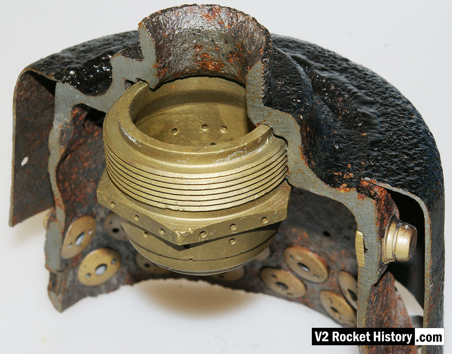
Cutaway section of fuel and liquid oxygen (LOX) injector pot. The exhibit shows the bell shaped thick inner wall of the burner with three tiers of fuel injector inserts (A,D, and E). The central copper alloy LOX spray injector is also well displayed in this image. The thin steel outer shell of the burner cup is shown and affords a good view of the head cavity that supplies fuel to the injector inserts – one A type injector is shown party cut through on the right, its rear portion showing inside the fuel cavity. V2RH image

Album: V2 rocket fuel injector inserts

Categories: Combustion V2 Missile relics

Tags: #Combustion and injection #Propellent injector system