No Picture

Sample set 3303D inserts
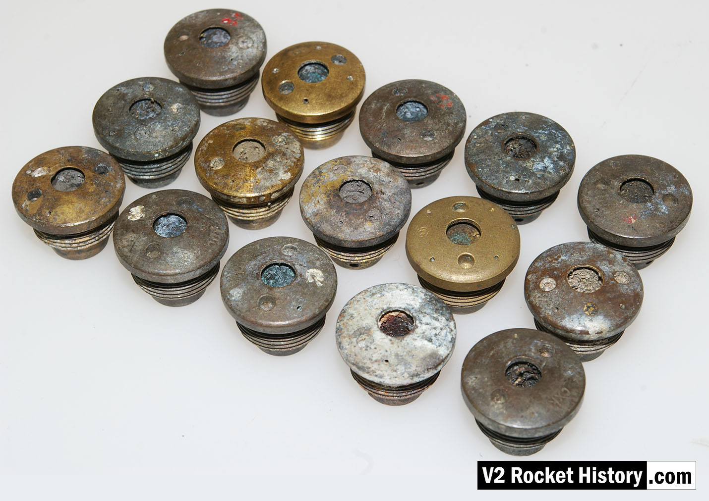
Sample set 3303D inserts

Sample set of 3303D type fuel injector inserts that were found in Peenemünde in part of a group that were bunched together in a space about 300mm in diameter with the remains of packaging. They appear to be manufacturing samples and and some have been graded with numbers 1,2,3, as well as with red and white paint to show the burner cup echelon position (C or D). Five different manufacturers are represented in this group. V2RH collection image

Album: V2 rocket fuel injector inserts

Categories: Combustion

Tags: #A4-V2 supply contractor #Propellent injector system #Combustion and injection #V2 Missile relics

No Picture

‘Einheitskopf’ Type 4B Injector head fragment

'Einheitskopf' Type 4B Injector head fragment

The injector head fragment shown here, is from an 4B 1000 kg thrust engine that was developed at Kummersdorf in 1938/39 by Dr Walter Thiel’s combustion research group. The fragment, clearly the remains of an explosion, was actually found in a scrap pile in Peenemüde but the engine was probably tested (and destroyed) at the Kummersdorf army testing station. V2RH collection image.

Album: V2 rocket fuel injector inserts

Categories: Combustion V2 Missile relics

Tags: #Combustion and injection #Propellent injector system #V2 Missile relics

No Picture

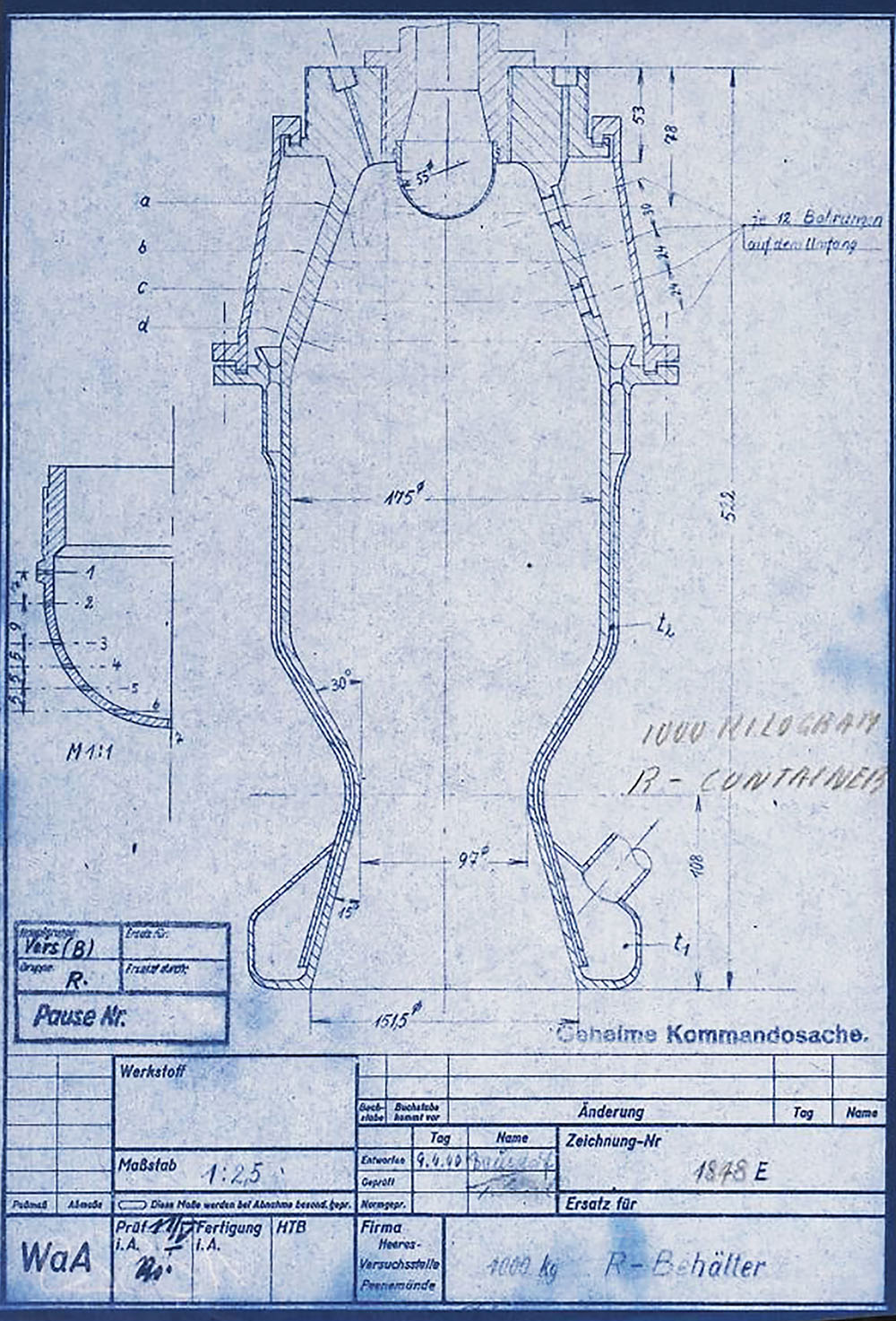
1000 kg 4B engine 1940

1000 kg 4B engine 1940

The injector head section of the 4B 1000kg thrust rocket engine is a precursor to the injector pot or ‘pre-chamber’ design used later for each of the 18-pots of the 25-ton V2 rocket engine. Most of the essential ingredients are shown in this drawing from 1940. Drawing no 1848E Deutsches Museum München online archive ref FA 014/12829

Album: V2 rocket fuel injector inserts

Categories: Combustion

Tags: #Combustion and injection #Propellent injector system #V2 Technical Drawings

No Picture

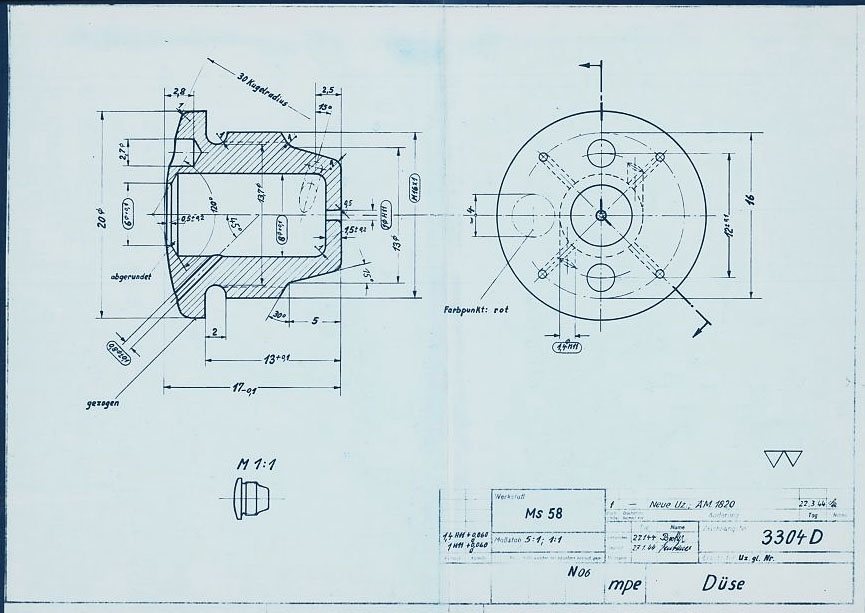
V2 Rocket standard screw-fit fuel Injector Insert 3304D 1944

V2 Rocket standard screw-fit fuel Injector Insert 3304D 1944

HAP11 drawing of standard 3304D fuel injector screw insert. showing details of primary swirl cavity and orrifice and all additional apertures including the four small cooling pores. HAP11 (Heimat-Artillerie-Park 11, AKA armament code: mpe), drawing number 4554D, Deutsches Museum München

Album: V2 rocket fuel injector inserts

Categories: Combustion Propellant flow

Tags: #Combustion and injection #Propellent injector system #V2 Technical Drawings

No Picture

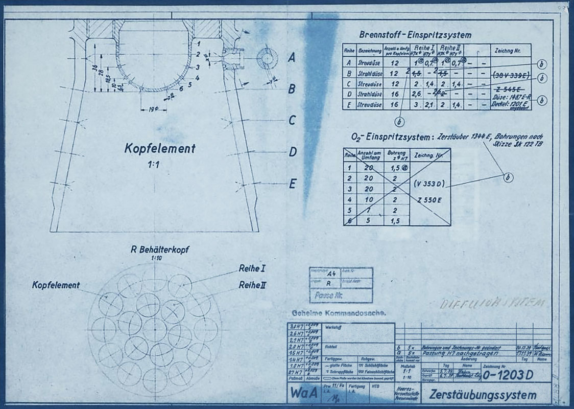
HVP Drawing of diffuser system 1939

HVP Drawing of diffuser system 1939

HVP drawing no 1203D showing burner cup ‘diffuser system’ disposition for 19-pot head (at this stage the 25 ton thrust injector head had nineteen so called ‘pre-chambers’ or pots as no central fuel valve was present). HVP drawing dated 1939.

Album: V2 rocket fuel injector inserts

Categories: Combustion Propellant flow

Tags: #Combustion and injection #Propellent injector system #V2 Technical Drawings