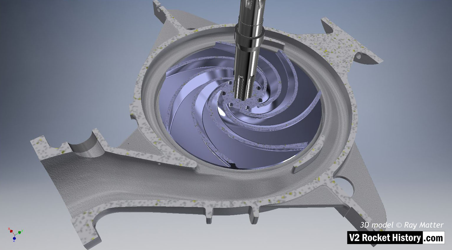
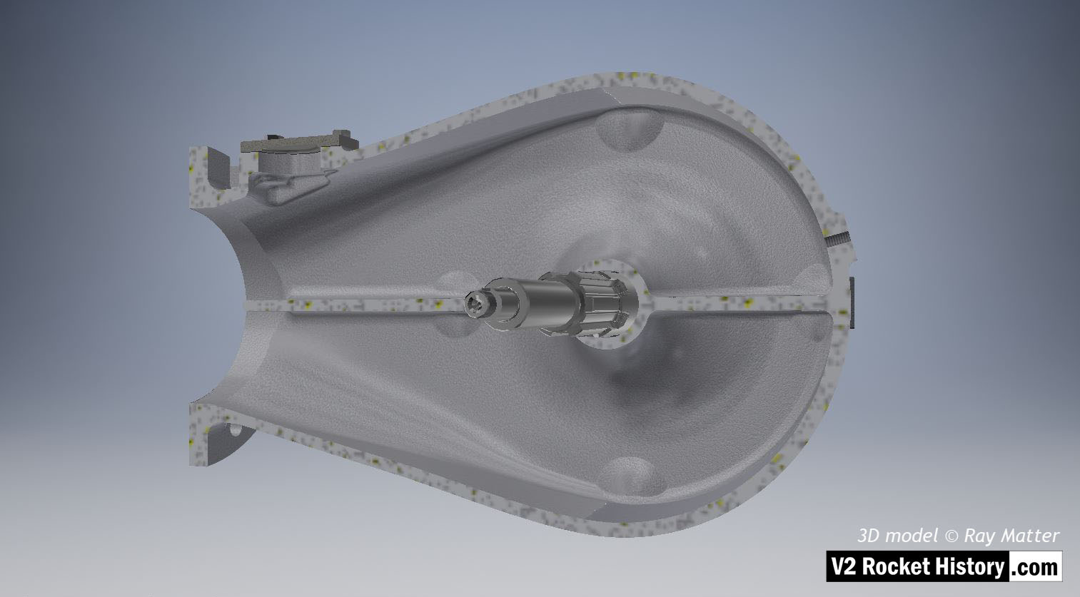
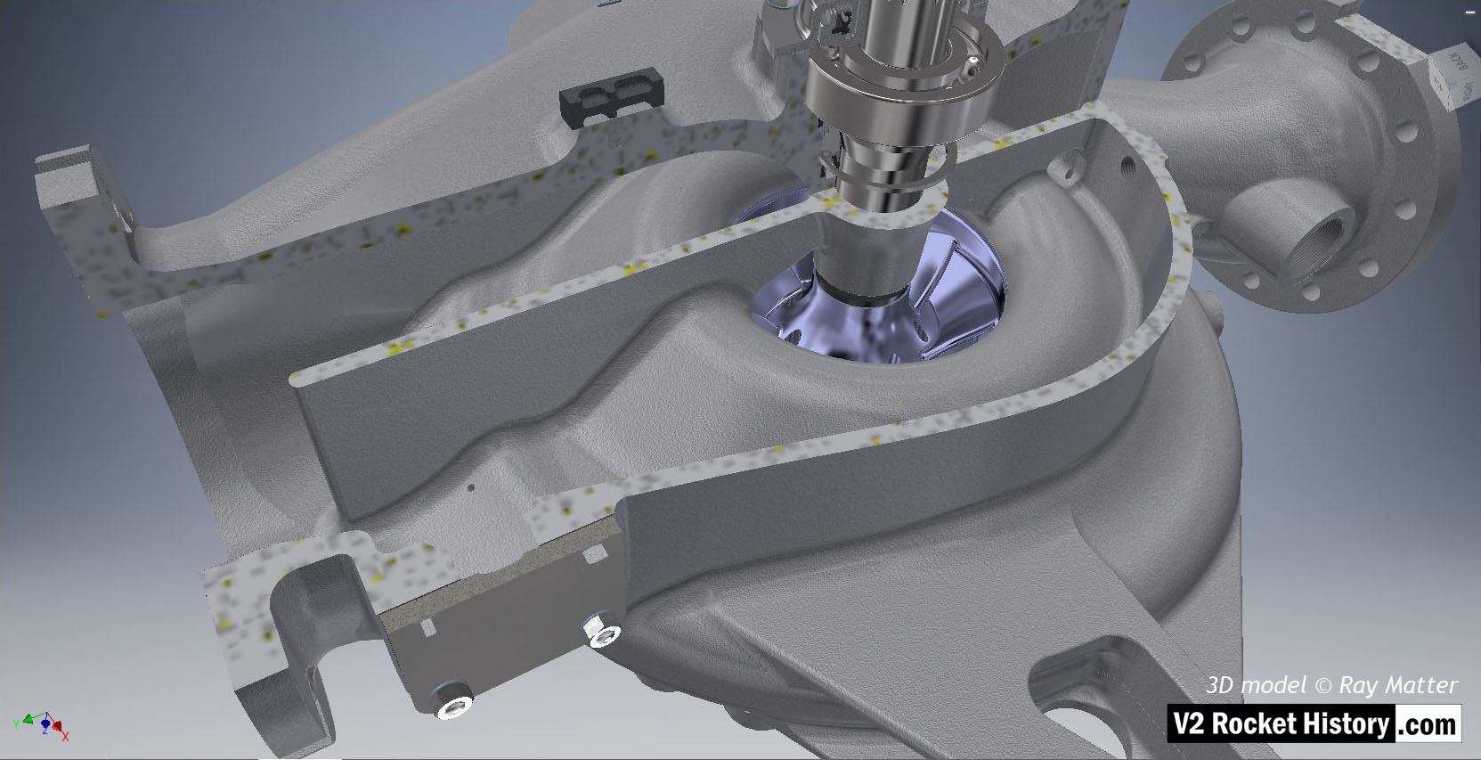
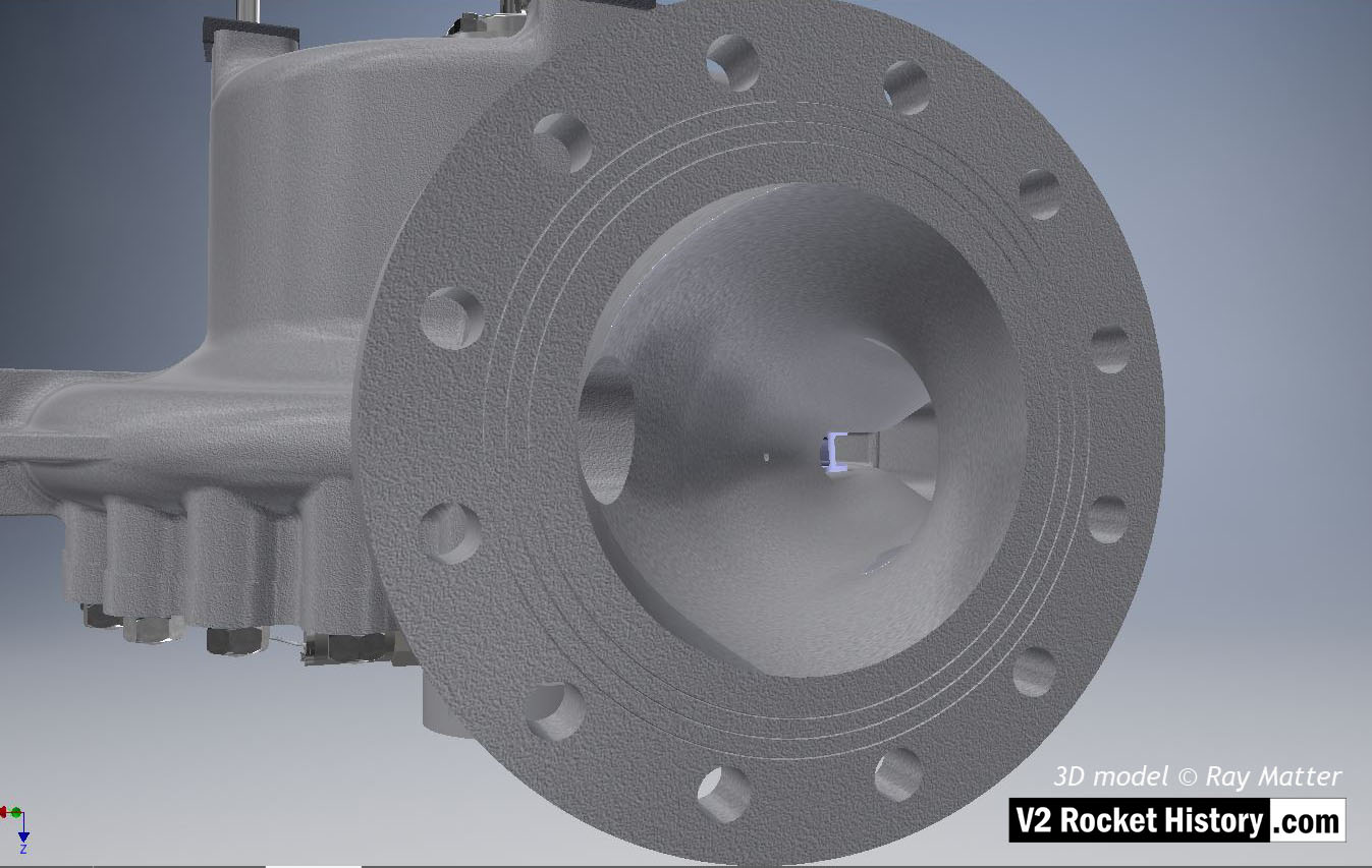
14 B-Pump sub-assembly elevation: impeller
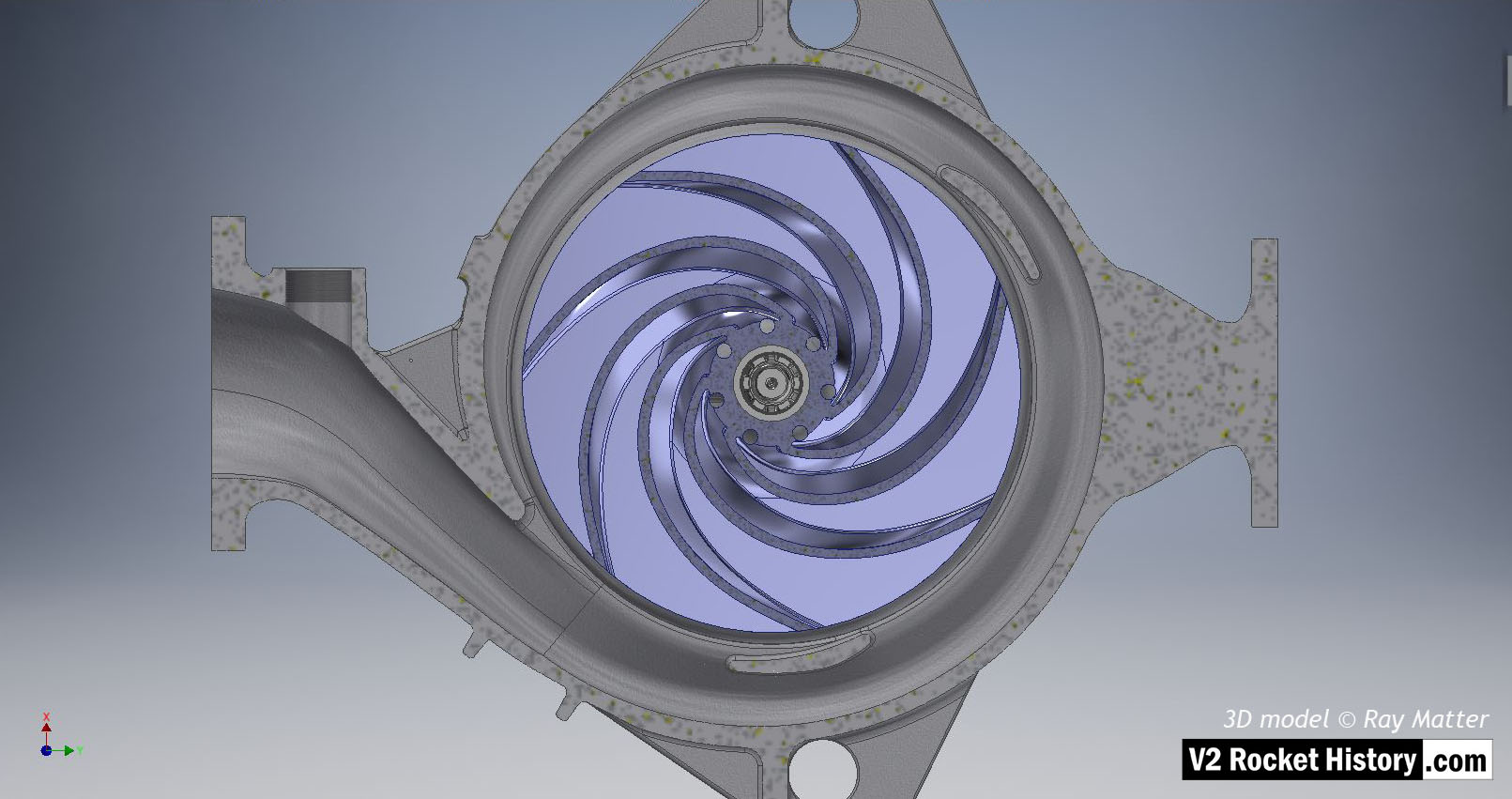
B (fuel) pump sub-assembly elevation view showing sectioned casing to reveal centrifugal pump impeller (in light purple for visibility). Outlet to left. The centrifugal pump impeller has been sectioned to remove one impeller face and reveal the curved vanes. The hub pass holes and end view of splined shaft are also shown. The spiral volute shape is very clear in this image. 3D model Ray Matter
Album: Turbopump 3D CAD
Categories: Turbo-pump
Tags: