B Pump housing, cut 32
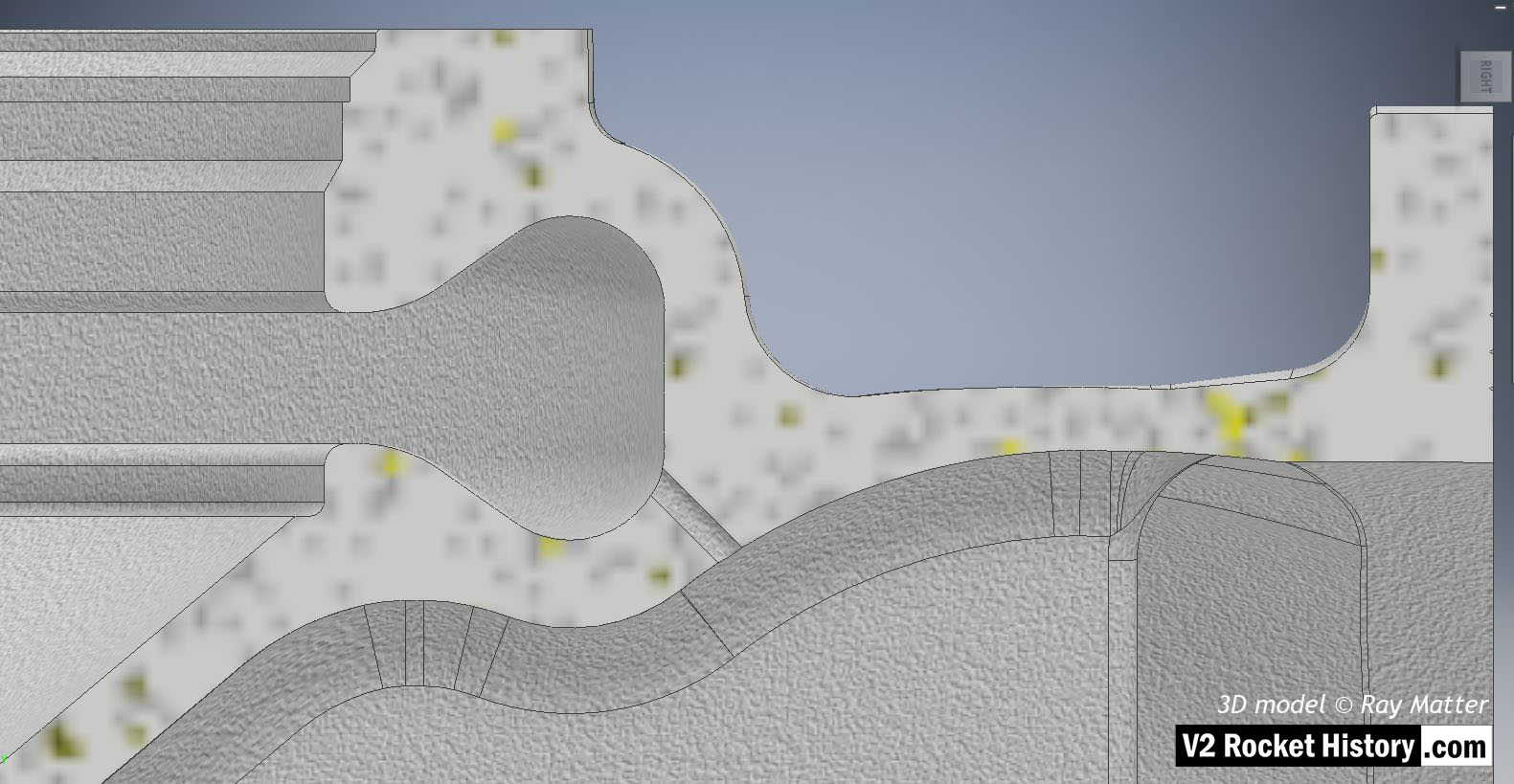
B pump housing showing sectioned inlet throat to the right and outlet to the left. Note self- purge pathway from high-pressure volute space into low-pressure fuel inlet throat. 3D model Ray Matter
Categories: Turbo-pump
Tags: