No Picture

V2 Turbo-pump: B Pump housing
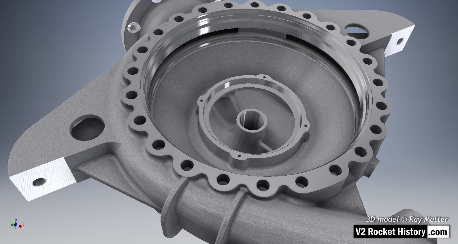
V2 Turbo-pump: B Pump housing

‘B’ fuel pump housing for V2 rocket engine turbopump showing cast and machined surfaces – some machined areas with obvious specular reflections. Of note are the rarely seen machined contact points on the integral support brackets and the larger areas in two locations in the ring of double ended bolt fixing holes seen at 12 and 6 o’clock. These areas allowed two ‘push’ screws to be threaded into corresponding locations in the face plate. These could then be screwed down to provide a pushing force to remove the face plate from the main housing seat. This retraction system was required owing to the very tight fit of the face plate due to the narrow ‘piston fit’ tolerances and the vacuum effect of a soft gasket that was employed between the faces. 3D model by Ray Matter

Album: Turbopump 3D CAD

Categories: Turbo-pump

Tags: #3D CAD models

No Picture

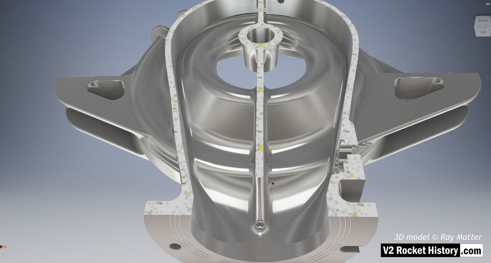
B pump housing – sectioned – showing self-purge orifice

B pump housing - sectioned - showing self-purge orifice

B pump housing with notional surface polish to show shape and detail (such a surface was not used on the actual pump casing). The casing nearest the turbine has been cutaway to reveal internal detail. The small self-purge orifice can be seen in this view, lower middle to the right of separator. 3D model Ray Matter

Album: Turbopump 3D CAD

Categories: Turbo-pump

Tags: #3D CAD models
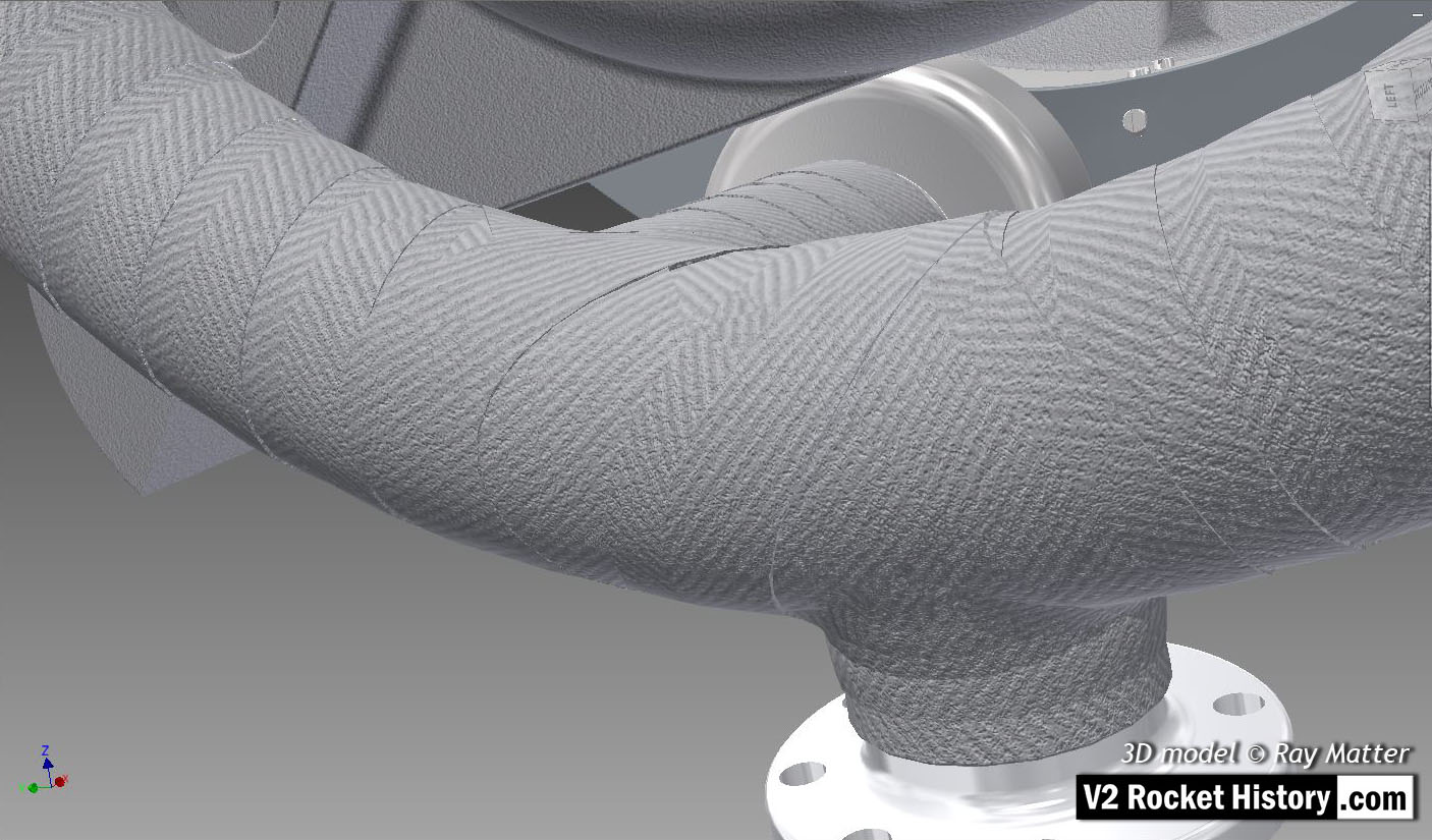
No Picture

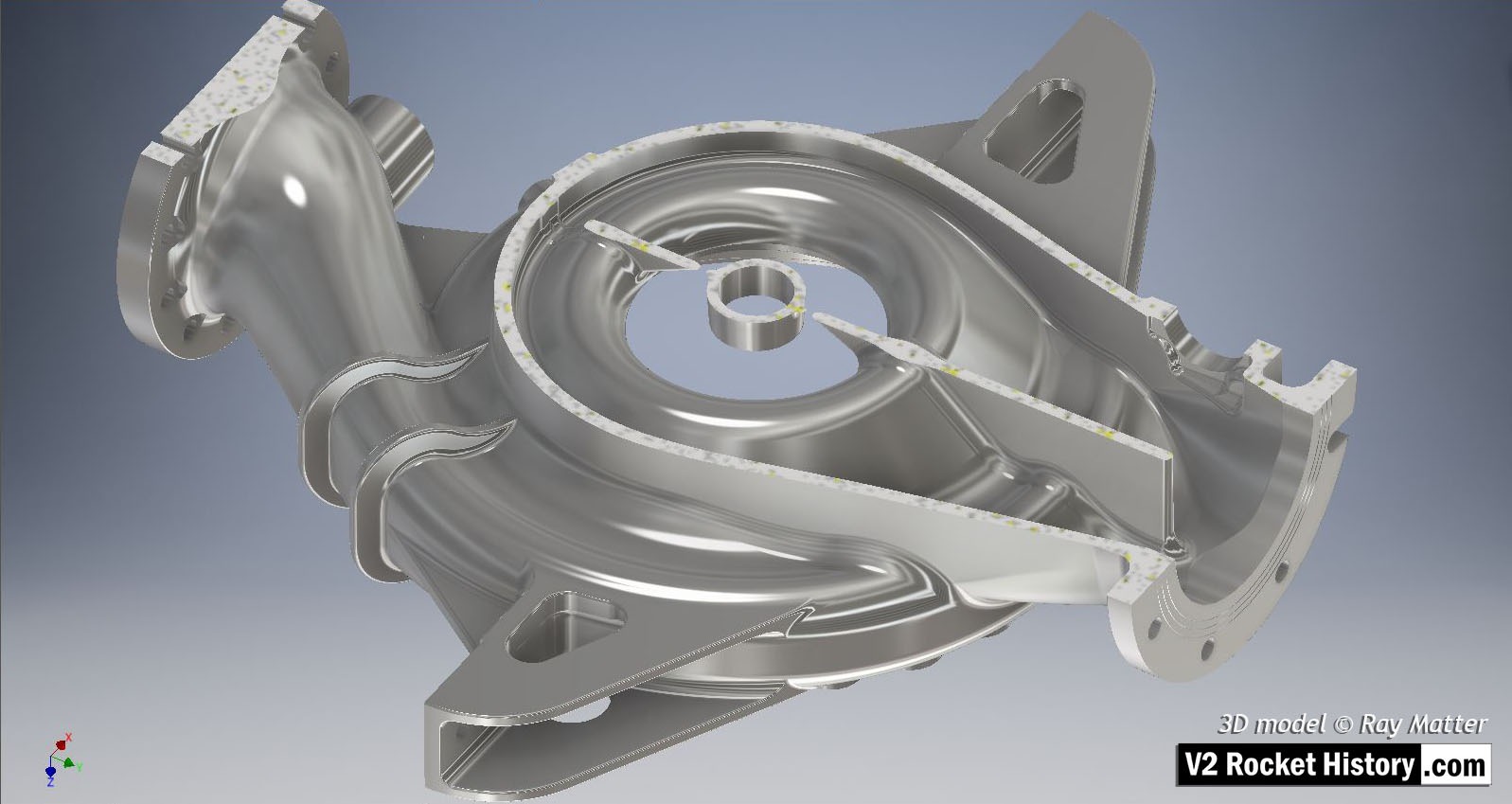
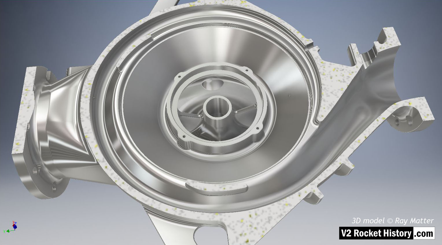
B pump housing – sectioned / polished

B pump housing - sectioned / polished

B pump housing from pump rotor side – notional surface polish to show shape and detail (such a surface was not used on the actual pump parts). The casing has been cut to show the internal rotor space detail. The outlet throat, right, and spiral volute space are displayed in this view as is the central fuel inlet. 3D model Ray Matter

Album: Turbopump 3D CAD

Categories: Turbo-pump

Tags: #3D CAD models