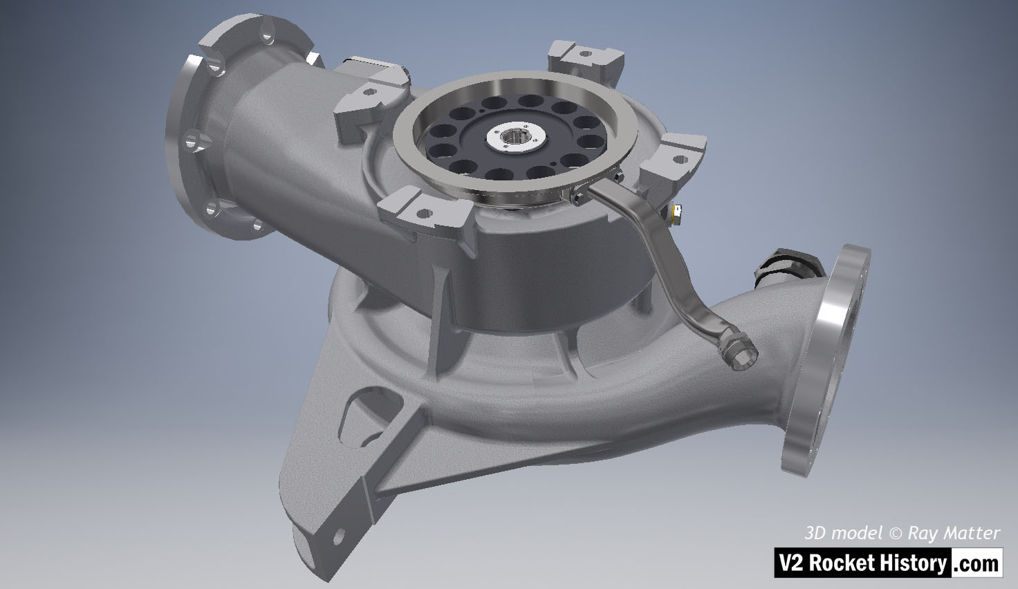
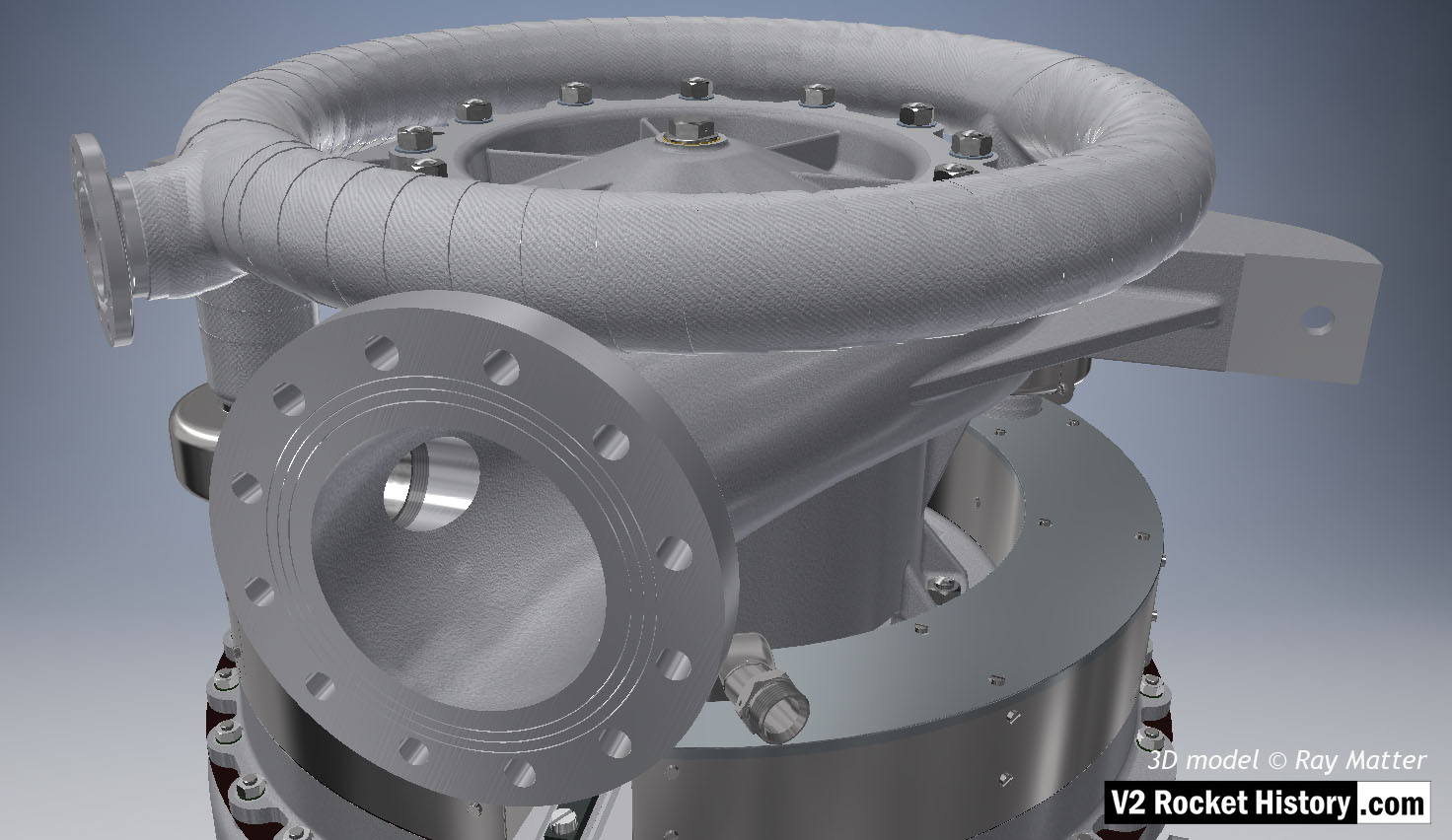
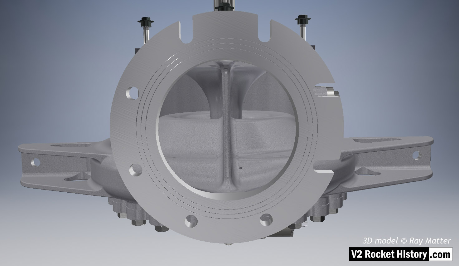
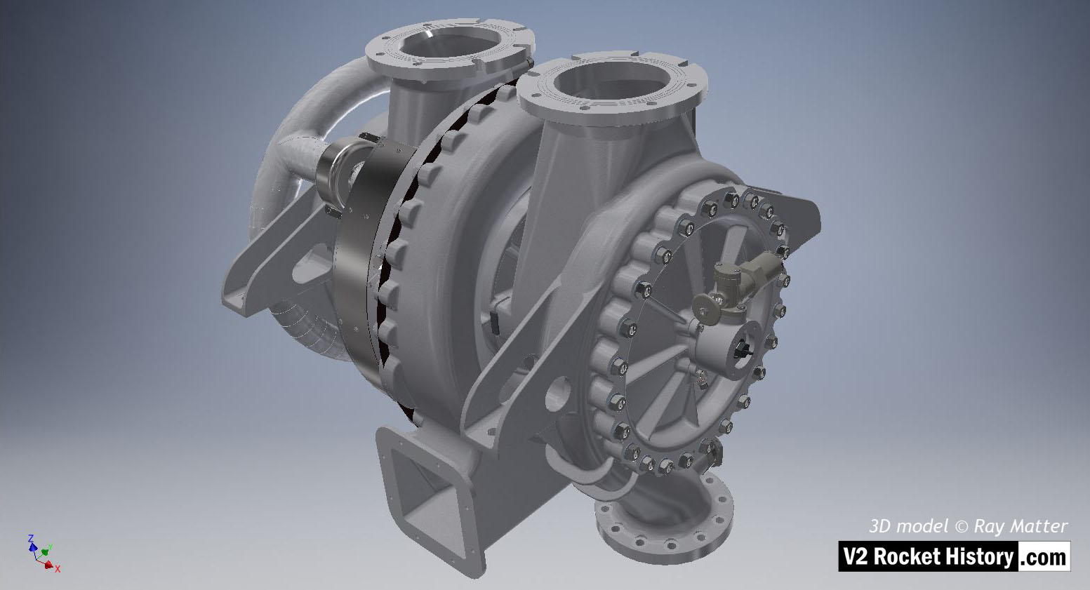
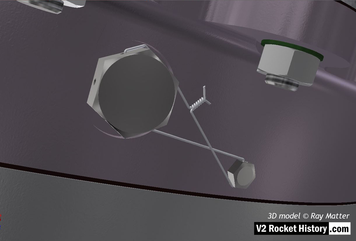
No Picture

Full assem. from A (LOX) Pump: 2

Full assem. from A (LOX) Pump: 2

Full assembly showing, from top, steam inlet ring manifold, LOX pump and portion of steam turbine assembly. View shows outlet flange facing camera. Note the three fine rings milled into flange face. The rings were designed to improve keying for the sealing ‘putty’ that was used to seal the connection between the flange face and the inlet pipe. 3D model Ray Matter

Album: Turbopump 3D CAD

Categories: Turbo-pump

Tags: #3D CAD models #Turbo-pump

No Picture

08 B-Pump Sub-assembly: Inlet flange

08 B-Pump Sub-assembly: Inlet flange

B-Pump Sub-assembly shown from top. View shows outlet flange facing camera – the splined drive shaft can just be seen at the top of the screen. Note the three fine rings milled into flange face.The rings were designed to improve keying for the ‘putty’ that was used to seal the connection between the flange face and the inlet pipe. Note, small self-purge orifice on the lower left of the inlet throat baffle. Unlike the upper purge hole in the LOX casing, the shallower face angle at the location of the hole in the fuel pump casing, was more accessible to drilling and was therefore not problematic. 3D model Ray Matter

Album: Turbopump 3D CAD

Categories: Turbo-pump

Tags: #3D CAD models #Turbo-pump

No Picture

V2 Turbopump: Full Assembly

V2 Turbopump: Full Assembly

Turbine powered propellant pumps for A4/V2 rocket engine – fuel pump on right. Full perspective assembly showing tubular ring steam inlet manifold with asbestos bandage extreme left, inlet flanges at top, frame support brackets, steam exhaust outlet square shape lower center. The overspeed trip switch can be seen just above center on fuel pump face plate. The fuel outlet flange can also been seen btm right of center. 3D model by Ray Matter

Album: Turbopump 3D CAD

Categories: Turbo-pump

Tags: #3D CAD models