
B Pump Housing: 22
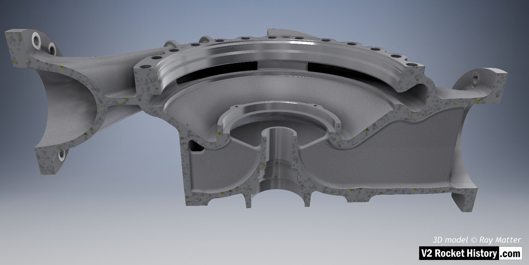
B Pump housing sectioned to show baffle and volute space area expansion as flow passes from inlet (right) to outlet (left). 3D model Ray Matter
Album: Turbopump 3D CAD
Categories: Turbo-pump
Tags:


B Pump housing sectioned to show baffle and volute space area expansion as flow passes from inlet (right) to outlet (left). 3D model Ray Matter
Album: Turbopump 3D CAD
Categories: Turbo-pump
Tags:

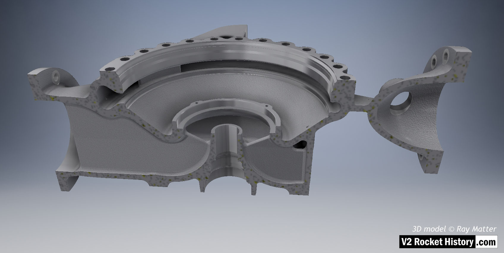
B Pump housing sectioned to show baffle with vent and volute space area expansion as flow passes from inlet (left) to outlet (right). 3D model Ray Matter
Album: Turbopump 3D CAD
Categories: Turbo-pump
Tags:

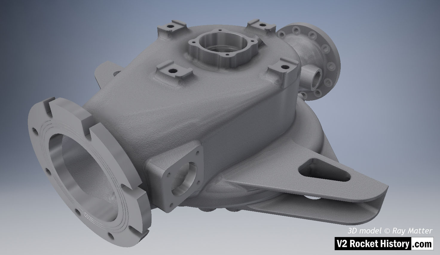
B (fuel) Pump sub-assembly, single piece casting showing machined (milled) areas without fittings. View shows inlet flange fastener slots and the throat aperture – facing right, initially blanked off by square plate, but towards the end of 1944 used for fuel return from the main fuel valve situated in the center of the thrust chamber injection head. 3D model Ray Matter
Album: Turbopump 3D CAD
Categories: Turbo-pump
Tags:

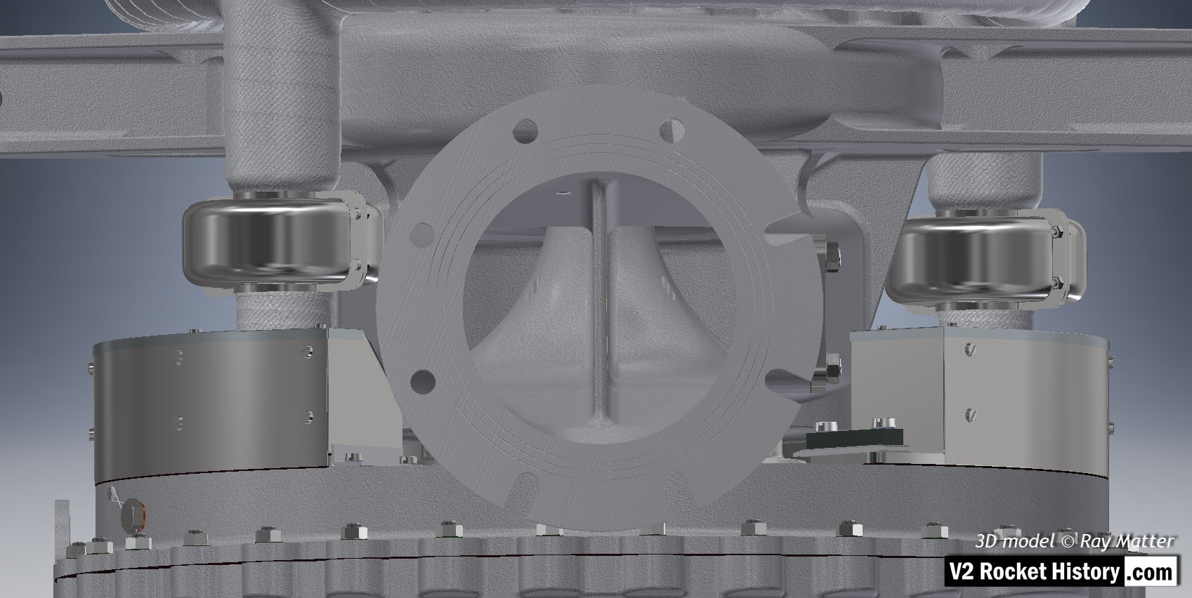
A (LOX) Pump close-up showing inlet flange, with fastener slots and holes, as well as the throat baffle. To the right and left of the flange, the steam inlets are shown – with steel cases covering the steam manifold connection flanges. Of special note in this view is the self-purge orifice seen at the top right-hand side of the inlet throat baffle. This hole allowed gas to escape from the top of the LOX volute space back to the low-pressure inlet throat and proved problematic in manufacturing and was revised in late 1944. 3D model Ray Matter
Album: Turbopump 3D CAD
Categories: Turbo-pump
Tags:

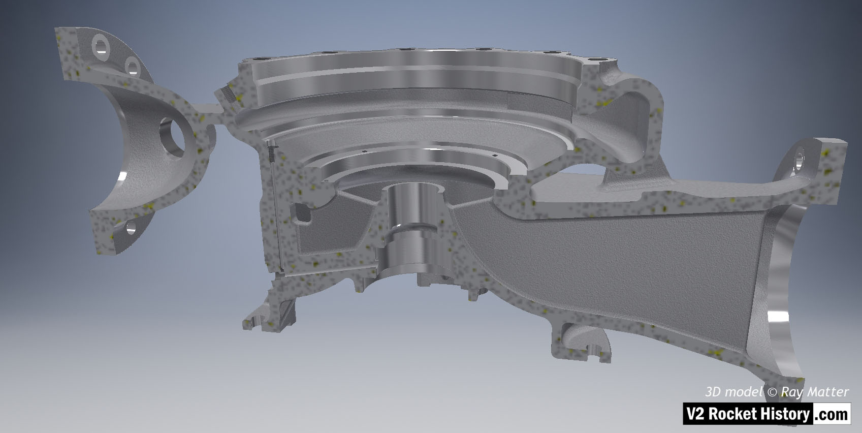
A (LOX) Pump housing sectioned to show baffle and volute space area expansion as flow passes from inlet (right) to outlet (left). Note cast and machined (milled) areas shown in this image – especially inlet aperture. 3D model Ray Matter
Album: Turbopump 3D CAD
Categories: Turbo-pump
Tags:
Copyright: V2 Rocket History
