
12 B-Pump assembly: inlet case
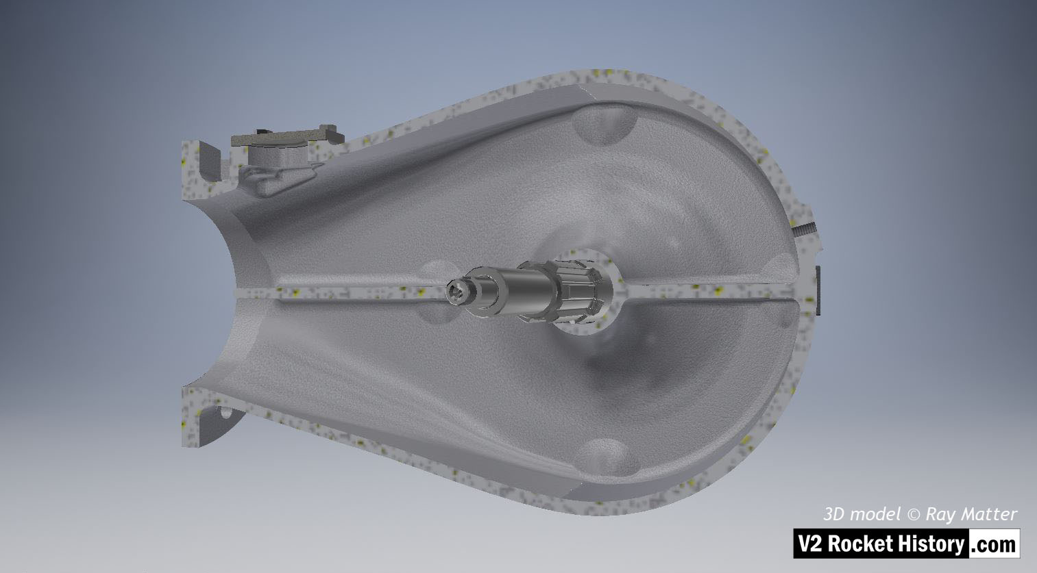
B-Pump sub-assembly casing sectioned to show shaft and fuel inlet chamber details. The throat blanking plate can be seen top left. 3D model Ray Matter
Album: Turbopump 3D CAD
Categories: Turbo-pump
Tags:


B-Pump sub-assembly casing sectioned to show shaft and fuel inlet chamber details. The throat blanking plate can be seen top left. 3D model Ray Matter
Album: Turbopump 3D CAD
Categories: Turbo-pump
Tags:

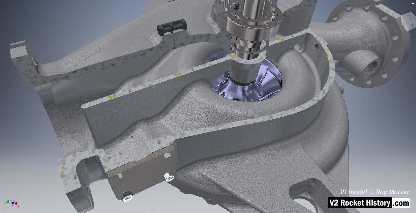
B-Pump sub-assembly sectioned to show fuel pump impeller inlet (purple area), baffle, and other shaft details. 3D model Ray Matter
Album: Turbopump 3D CAD
Categories: Turbo-pump
Tags:

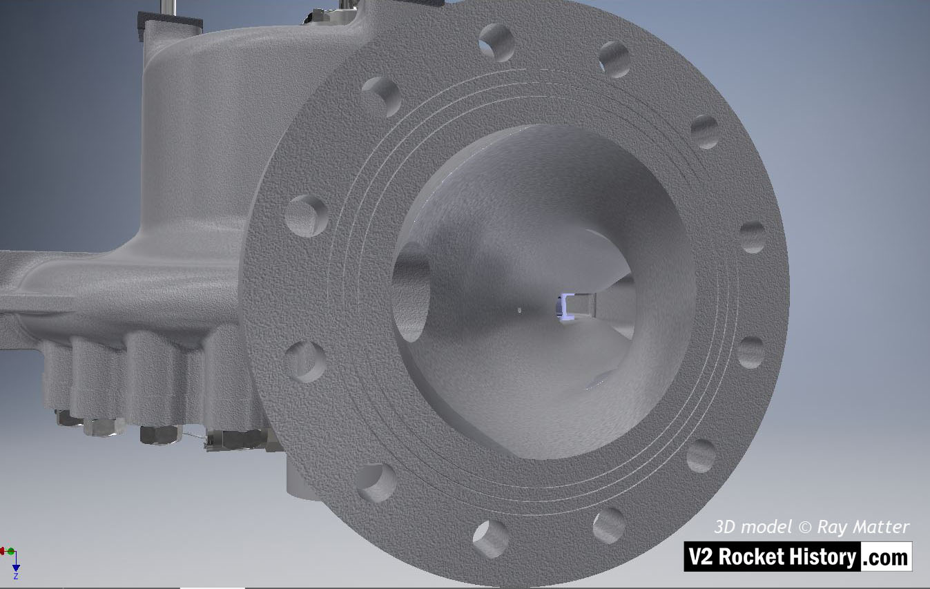
B-Pump sub-assembly close-up showing fuel outlet flange. Note the three fine rings milled into the flange face. The rings were designed to improve keying for the ‘putty’ that was used to seal the connection between the flange face and the flow choke. Both faces of the choke and top face of the fuel outflow connector had similar rings. 3D model Ray Matter
Album: Turbopump 3D CAD
Categories: Turbo-pump
Tags:

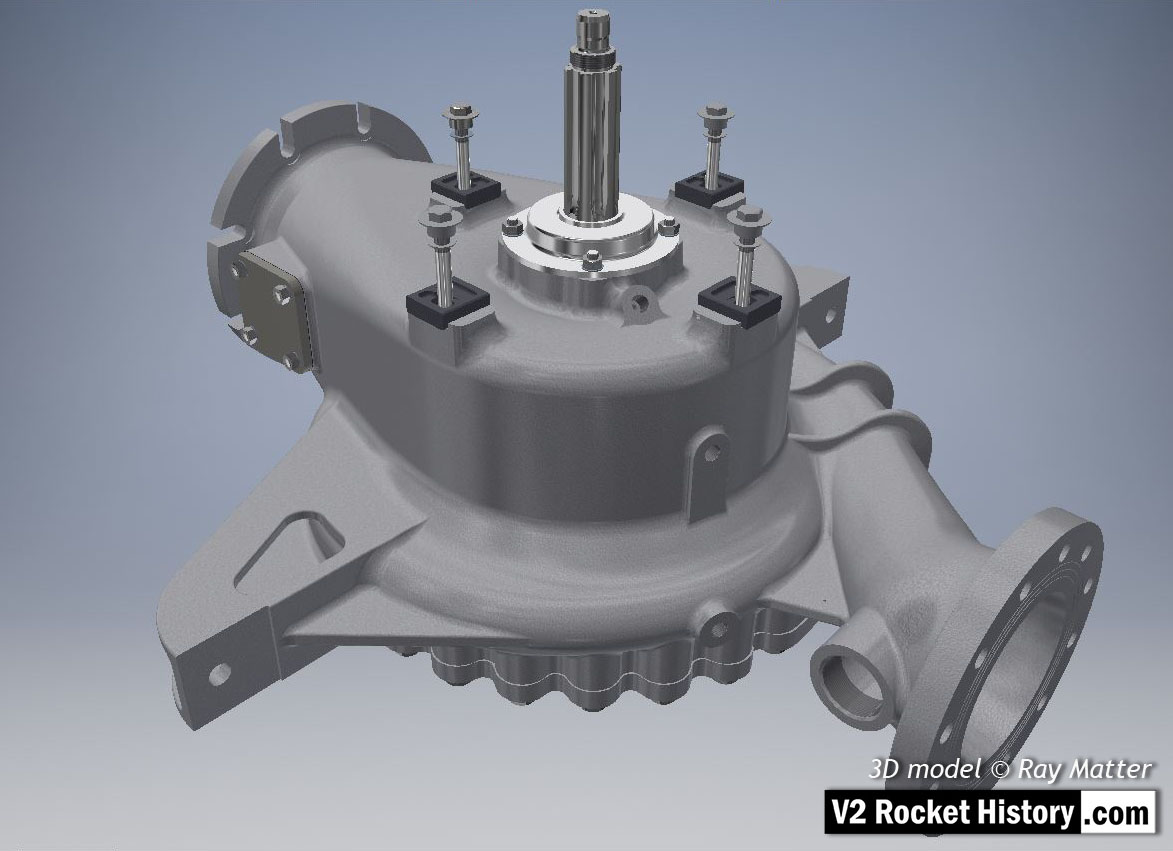
B-Pump sub-assembly, showing earlier version square inlet throat blanking plate (later versions employed a fuel return connection point mounted on this plate).
Fastenings, turbine case contact furniture, splined turbine connection shaft, and shaft seal cap are also shown. 3D model Ray Matter
Album: Turbopump 3D CAD
Categories: Turbo-pump
Tags:

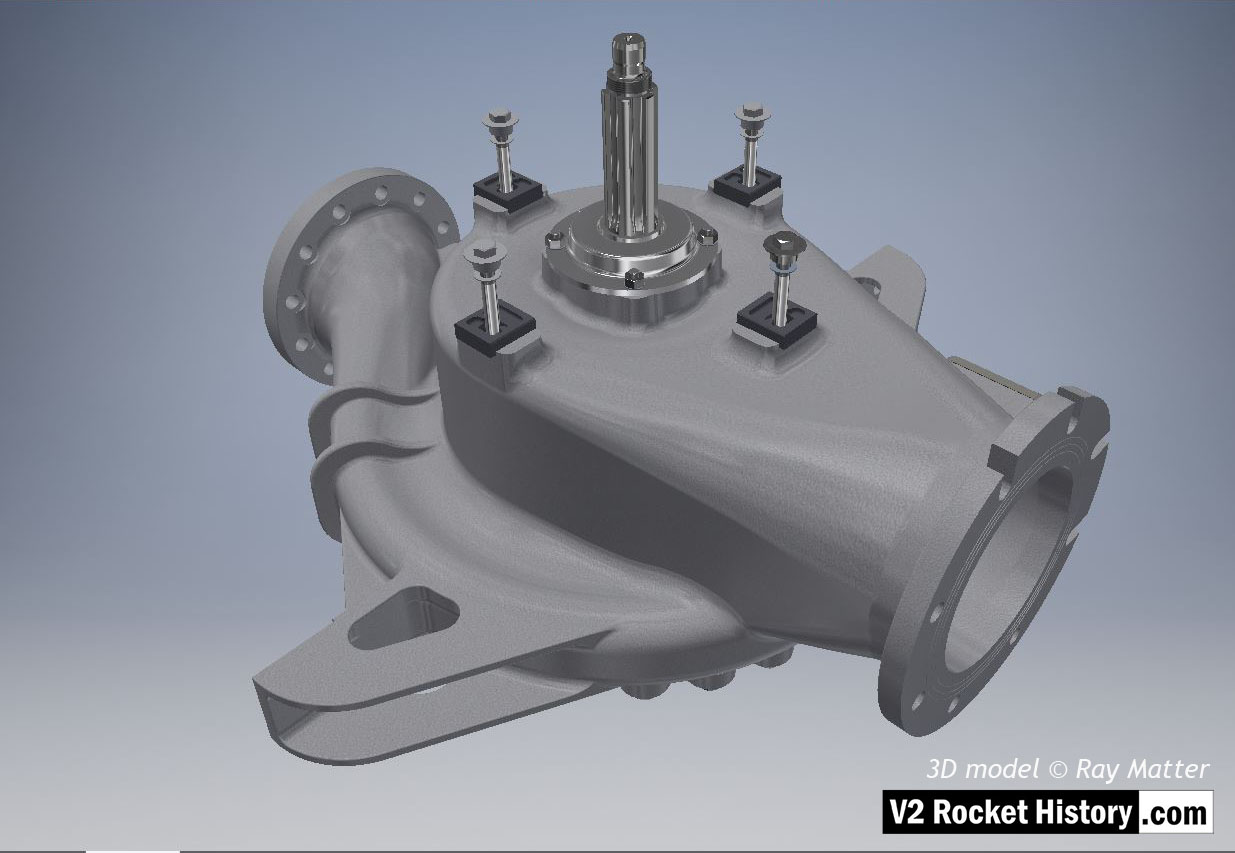
B-Pump sub-assembly complete with fastenings, turbine case contact furniture, splined turbine connection shaft, and shaft seal cap. 3D model Ray Matter
Album: Turbopump 3D CAD
Categories: Turbo-pump
Tags:
Copyright: V2 Rocket History
