No Picture

Detail of over-speed trip
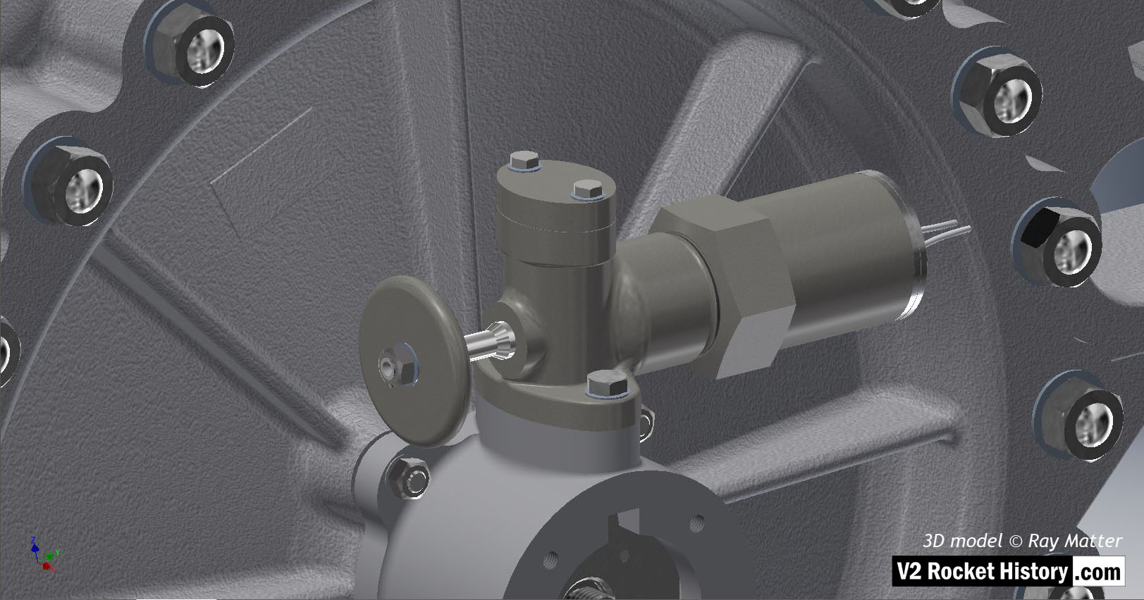
Detail of over-speed trip

Detail of fuel pump face plate showing over-speed switch and mounting. The switch plunger (part with disc shaped hand knob on left) is shown in the out or armed position. The RPM of the tubo-pump (TP) was not governed but this safety mechanism shut the TP down permanently when the RPM reached 5000. Although rarely changed, thin shims could be used to reduce or increase this speed. 3D model Ray Matter

Album: Turbopump 3D CAD

Categories: Turbo-pump

Tags: #3D CAD models

No Picture

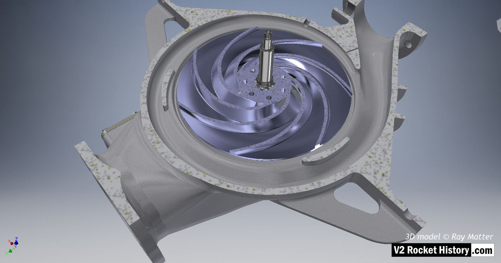
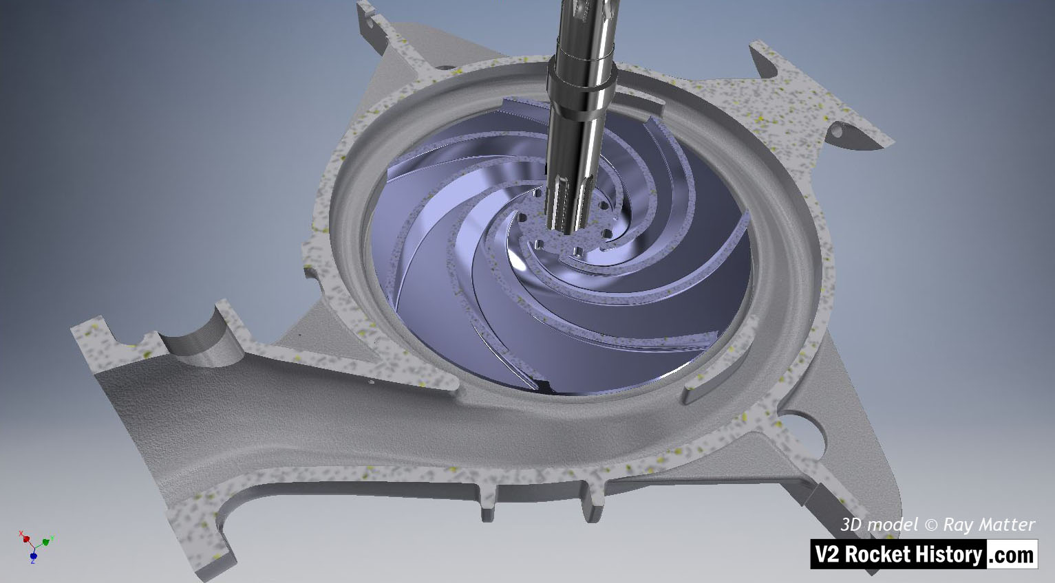
15 B-Pump sub-assembly: impeller

15 B-Pump sub-assembly: impeller

B (fuel) pump sub-assembly showing sectioned casing to reveal centrifugal pump impeller (in light purple for visibility). Outlet to top right. The centrifugal pump rotor has been sectioned to remove one impeller face and reveal the curved vanes.The shaft and spiral volute space shape is very clear in this image. 3D model Ray Matter

Album: Turbopump 3D CAD

Categories: Turbo-pump

Tags: #3D CAD models
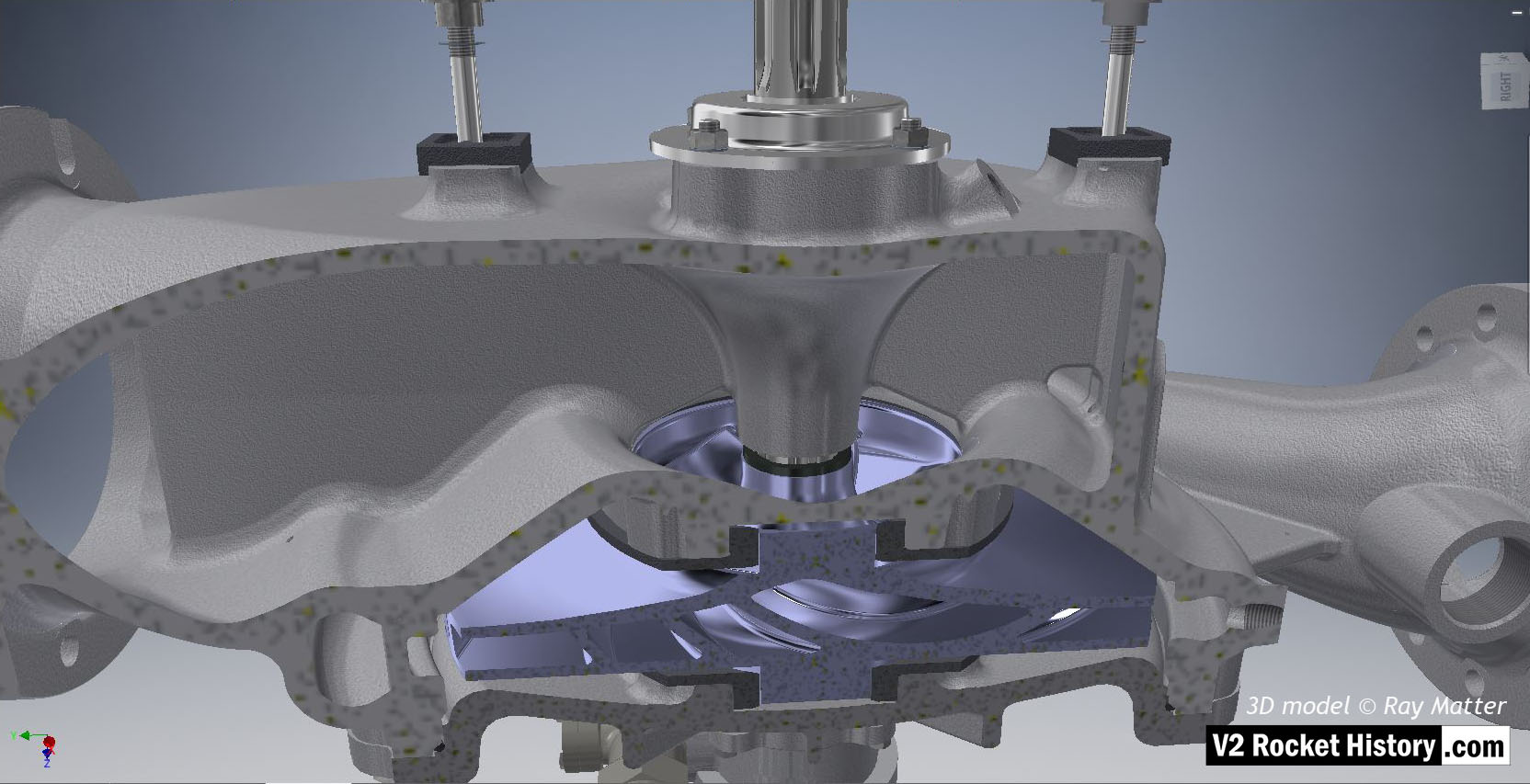
No Picture

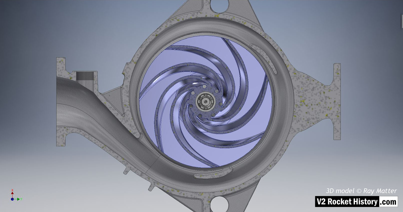
14 B-Pump sub-assembly elevation: impeller

14 B-Pump sub-assembly elevation: impeller

B (fuel) pump sub-assembly elevation view showing sectioned casing to reveal centrifugal pump impeller (in light purple for visibility). Outlet to left. The centrifugal pump impeller has been sectioned to remove one impeller face and reveal the curved vanes. The hub pass holes and end view of splined shaft are also shown. The spiral volute shape is very clear in this image. 3D model Ray Matter

Album: Turbopump 3D CAD

Categories: Turbo-pump

Tags: #3D CAD models