No Picture

V2 turbo-pump turbine and pump impeller shaft assembly

V2 turbo-pump turbine and pump impeller shaft assembly

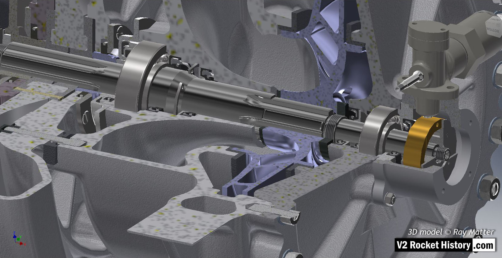
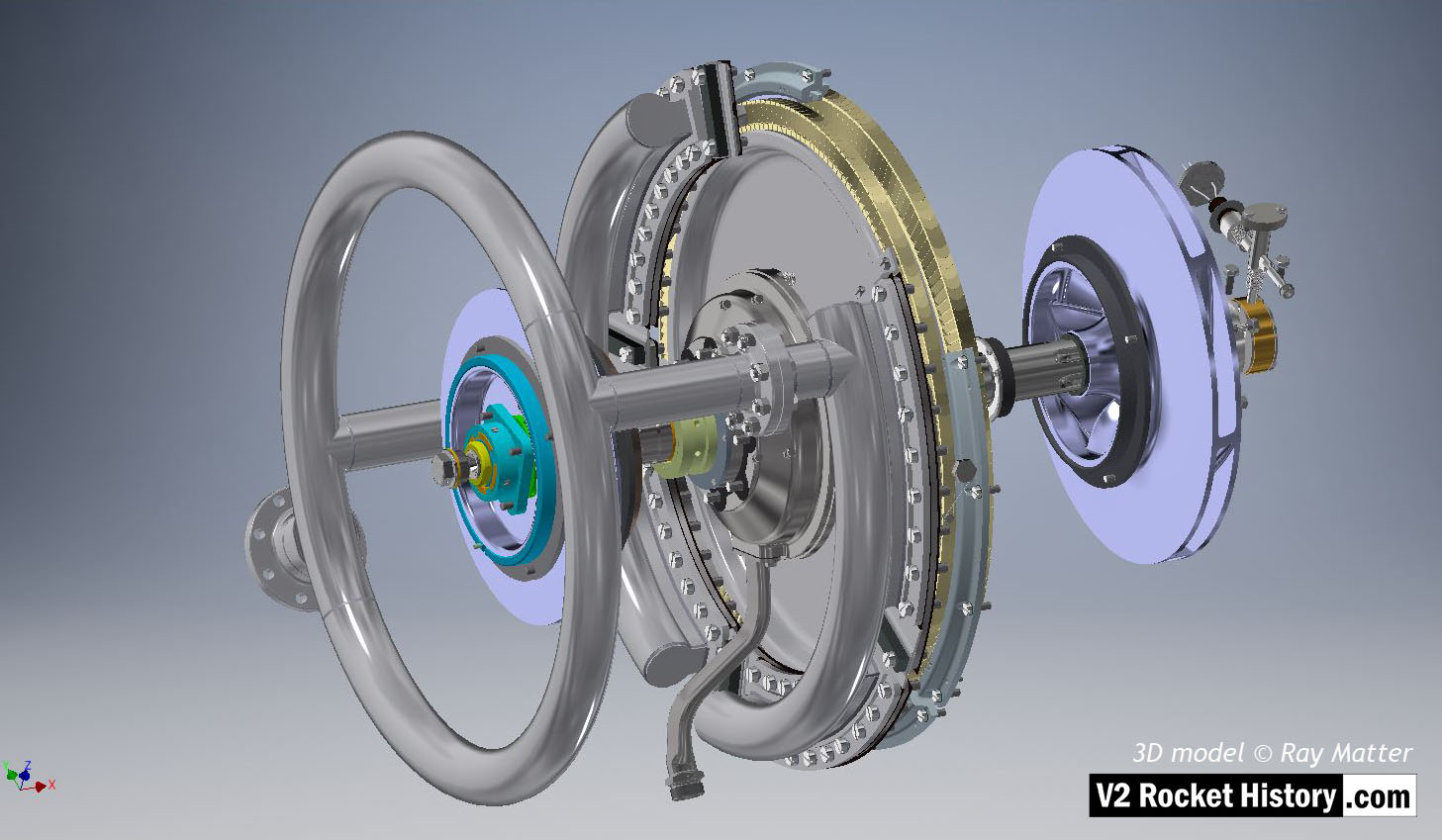
V2 turbo-pump turbine and pump impeller shaft assembly showing steam turbine rotor with nozzle assembly and steam inlet manifold distributor ring. The two rows of steam buckets can seen on rotor rim. Fuel pump impeller (purple) and over-speed switch are shown to the right. LOX pump impeller (purple) with journal bearing box and four sectional bronze bearings visible. An overboard dump pipe can be seen lower left of steam rotor. 3D model Ray Matter

Album: Turbopump 3D CAD

Categories: Turbo-pump

Tags: #3D CAD models

No Picture

03A Quartered Assym. shown inverted

03A Quartered Assym. shown inverted

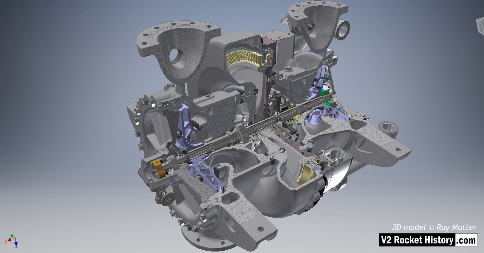
Turbine powered propellant pumps for A4/V2 rocket engine. The assembly is shown quarter sectioned and inverted with the propellant outlet flanges to the top and fuel pump on left, with inlet flanges at btm. The overspeed trip switch can be seen just below center on fuel pump face plate – the copper alloy centrifugal trip rotor is clearly visible in the trip-switch housing. 3D model by Ray Matter

Album: Turbopump 3D CAD

Categories: Turbo-pump

Tags: #3D CAD models
No Picture

02 V2 turbo-pump turbine and pump rotor shaft assembly

02 V2 turbo-pump turbine and pump rotor shaft assembly

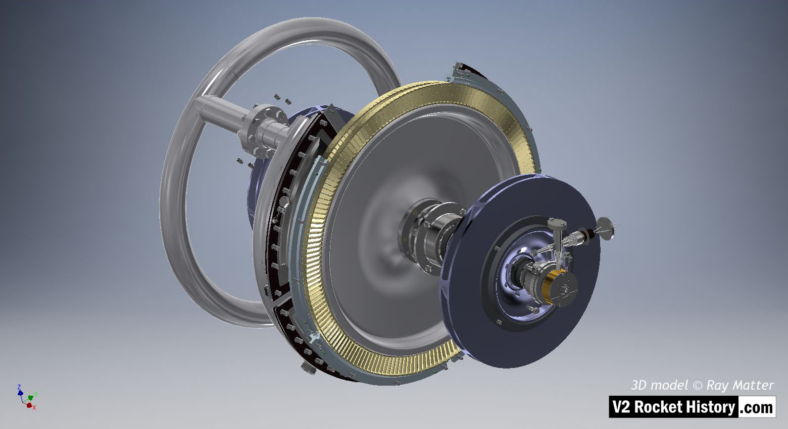
V2 turbo-pump turbine and pump impeller shaft assembly showing steam turbine rotor with nozzle assembly and steam inlet manifold distributor ring to left. The two rows of steam buckets can seen on rotor rim as well as three of the four sets of stationary steam return blades. Fuel pump impeller and over-speed switch are shown to the right. 3D model Ray Matter

Album: Turbopump 3D CAD

Categories: Turbo-pump

Tags: #3D CAD models