No Picture

V2 Rocket standard screw-fit fuel Injector Insert 3304D 1944
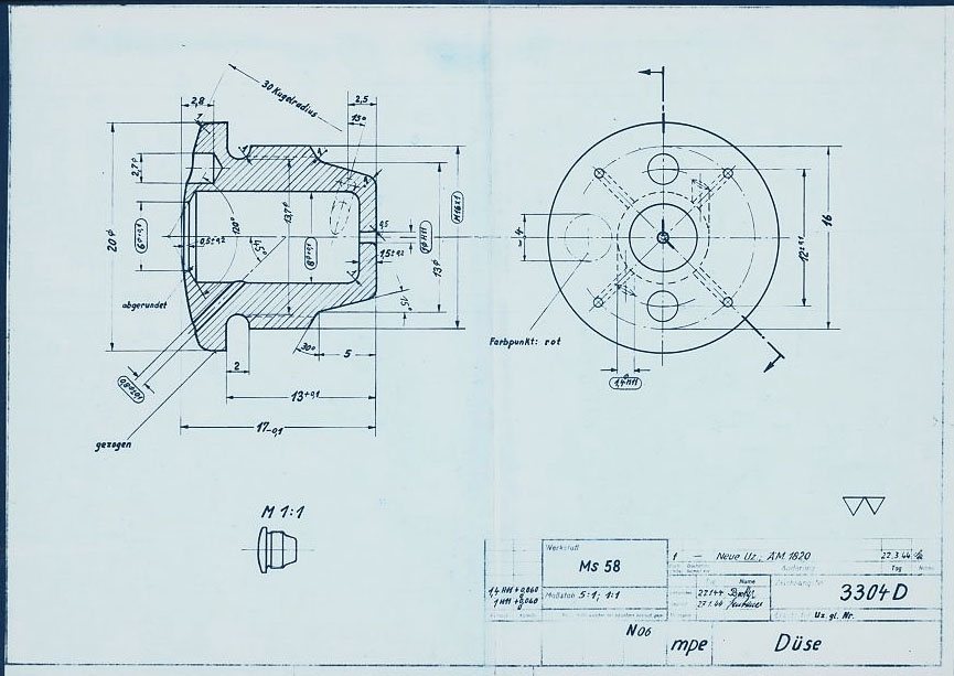
V2 Rocket standard screw-fit fuel Injector Insert 3304D 1944

HAP11 drawing of standard 3304D fuel injector screw insert. showing details of primary swirl cavity and orrifice and all additional apertures including the four small cooling pores. HAP11 (Heimat-Artillerie-Park 11, AKA armament code: mpe), drawing number 4554D, Deutsches Museum München

Album: V2 rocket fuel injector inserts

Categories: Combustion Propellant flow

Tags: #Combustion and injection #Propellent injector system #V2 Technical Drawings

No Picture

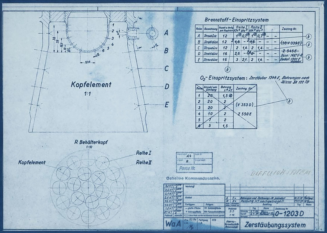
HVP Drawing of diffuser system 1939

HVP Drawing of diffuser system 1939

HVP drawing no 1203D showing burner cup ‘diffuser system’ disposition for 19-pot head (at this stage the 25 ton thrust injector head had nineteen so called ‘pre-chambers’ or pots as no central fuel valve was present). HVP drawing dated 1939.

Album: V2 rocket fuel injector inserts

Categories: Combustion Propellant flow

Tags: #Combustion and injection #Propellent injector system #V2 Technical Drawings

No Picture

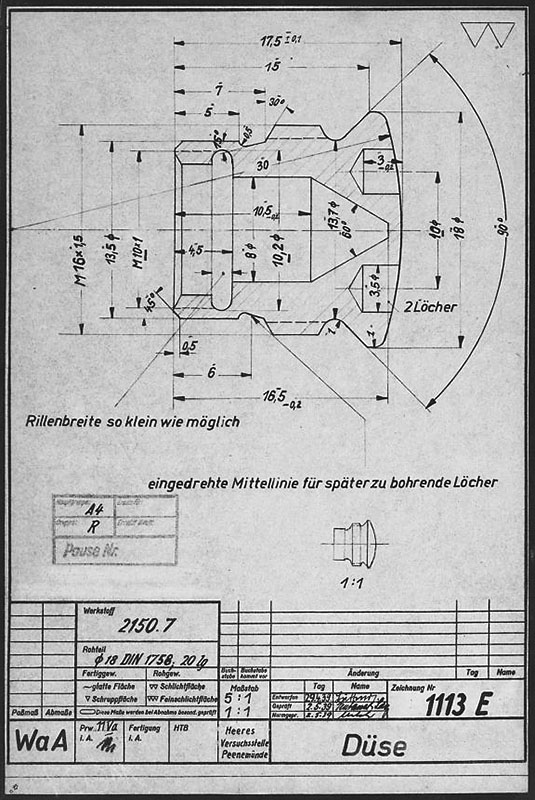
Drawing of fuel nozzle Insert 1113E 1939

Drawing of fuel nozzle Insert 1113E 1939

Drawing from the Army Experimental Station Peenemünde dated 1939. The specification describes an insert template that could be used for a range of outlet and inlet orifice sizes. The German text beginning (eingedrehte …) translates as ‘Center-line of screw used for holes to be drilled later’, and the hole dimensions are not specified on this document. HVP drawing number 1113 E, Deutsches Museum München

Album: V2 rocket fuel injector inserts

Categories: Combustion Propellant flow

Tags: #Combustion and injection #Propellent injector system #V2 Technical Drawings
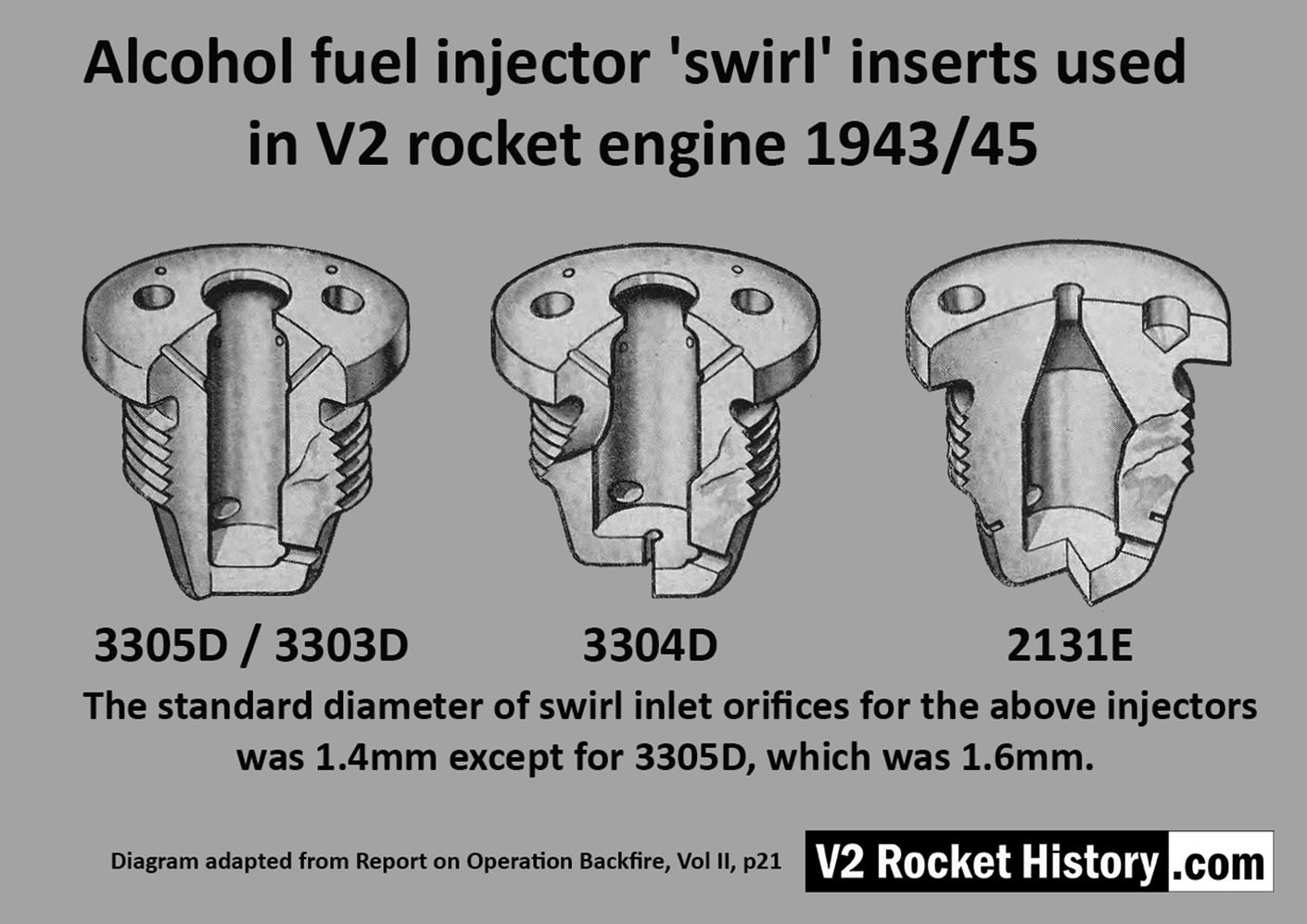
No Picture

Standard V2 Rocket fuel Injector Inserts

Standard V2 Rocket fuel Injector Inserts

Diagram showing cut-away presentations of the settled configuration of standard four ‘swirl’ inserts used in the V2 rocket engine’s 18-pot head from 1943 until the end of the war. The inserts are shown with their drawing code identification. All of the insert types used in the injector head are shown, however there were additional screw-in type fuel supply inserts, used to provide a fuel cooling balance function, located radially in the lower part of the combustion cavity.

Album: V2 rocket fuel injector inserts

Categories: Combustion Propellant flow

Tags: #Combustion and injection #Propellent injector system
No Picture

Test Rig With E Type Insert

Test Rig With E Type Insert

Single nozzle insert test rig used by V2 Rocket History to test spray shape and volume at fluid supply pressures consistent with fuel pressures specified for the injector head of summer 1944. A 2131E fuel injector insert is installed in the holder at the front of the test rig, but as the thread was the same on all inserts the nozzle can be changed for other models easily with aid of a pin spanner. See video for a demonstration of this simple test system.

Album: V2 rocket fuel injector inserts

Categories: Combustion Propellant flow

Tags: #Combustion and injection #Propellent injector system