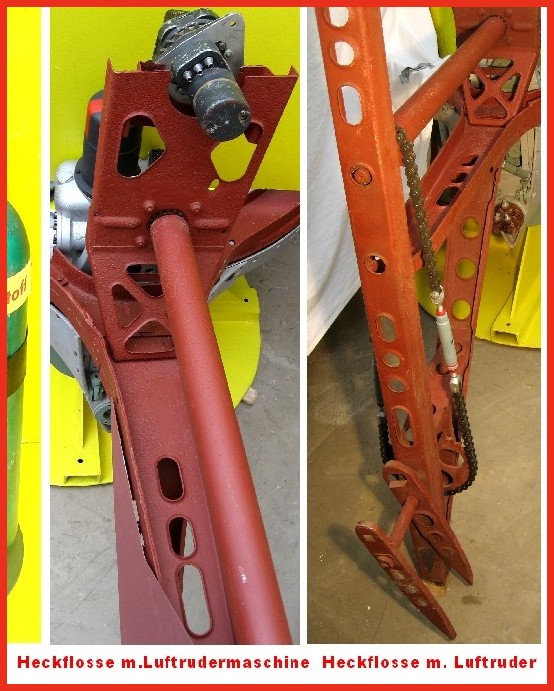
A4-V2 air rudder detail. ©THBC
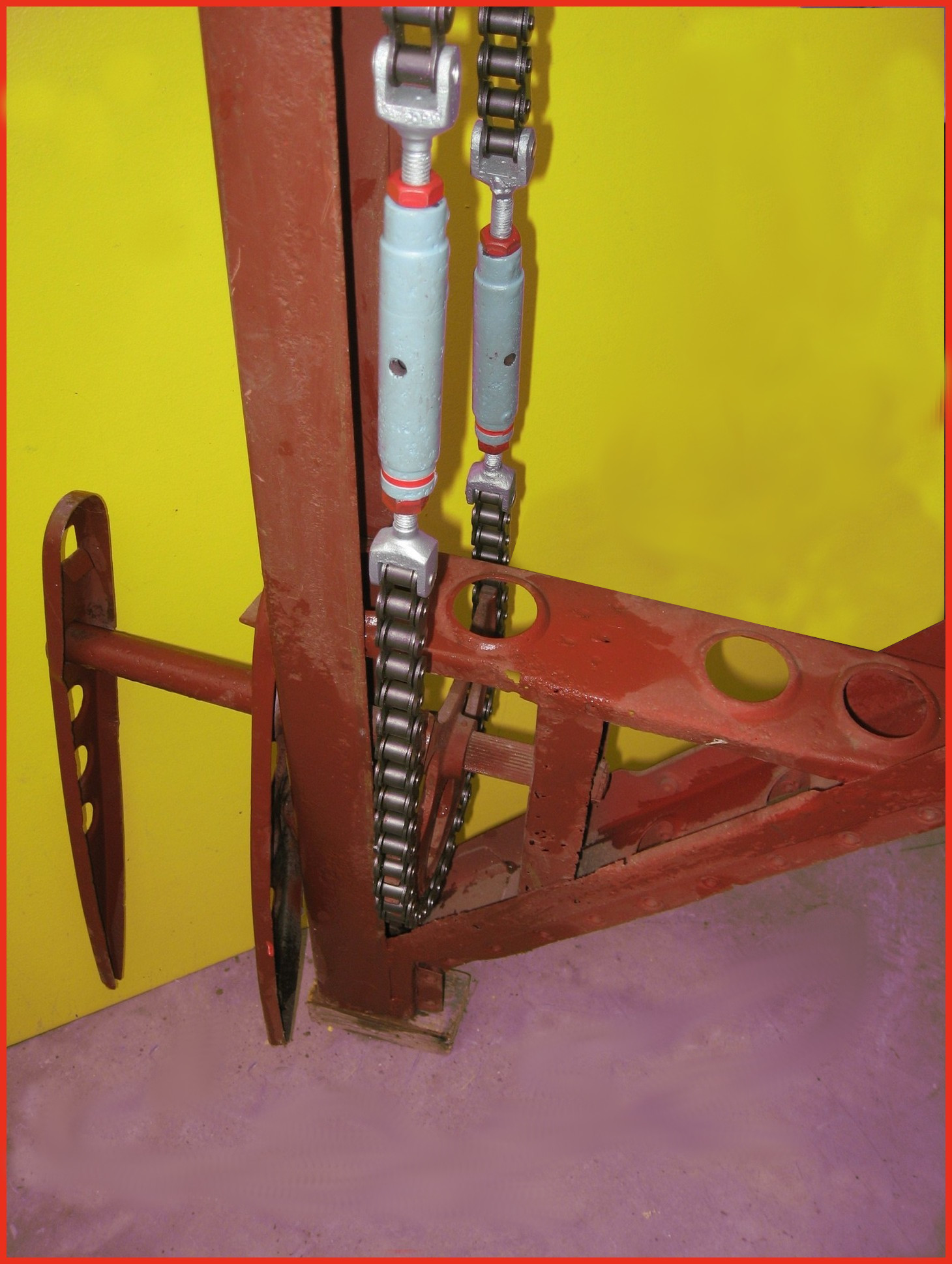
Photo shows restored air-rudder and fin detail. The grey painted barrel-strainers are both adjusted independently to reduce slack in the drive chain and avoid introducing a deflection bias in the air rudder. The 1.9kg counterbalance weight normally located at the top of the trim fin (or air rudder) is missing in this presentation. This excellent restoration is the work of Horst Beck. Photo copyright: The Horst Beck Collection
Album: A4-V2 Hydraulic servo and electric trim motor
Categories: Missile guidence Sub-assemblies
Tags: