No Picture

18-pot head: Cutaway 2

18-pot head: Cutaway 2

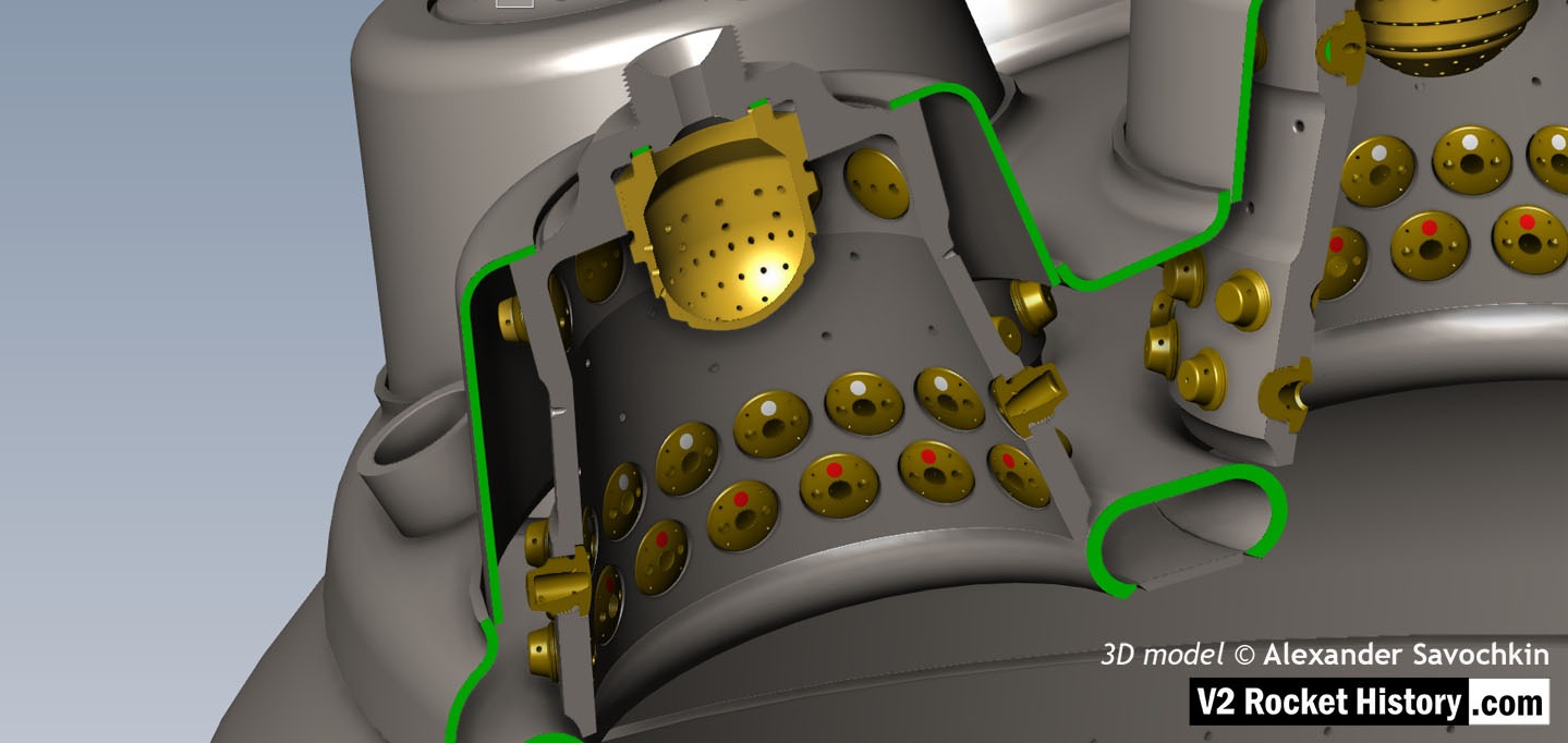
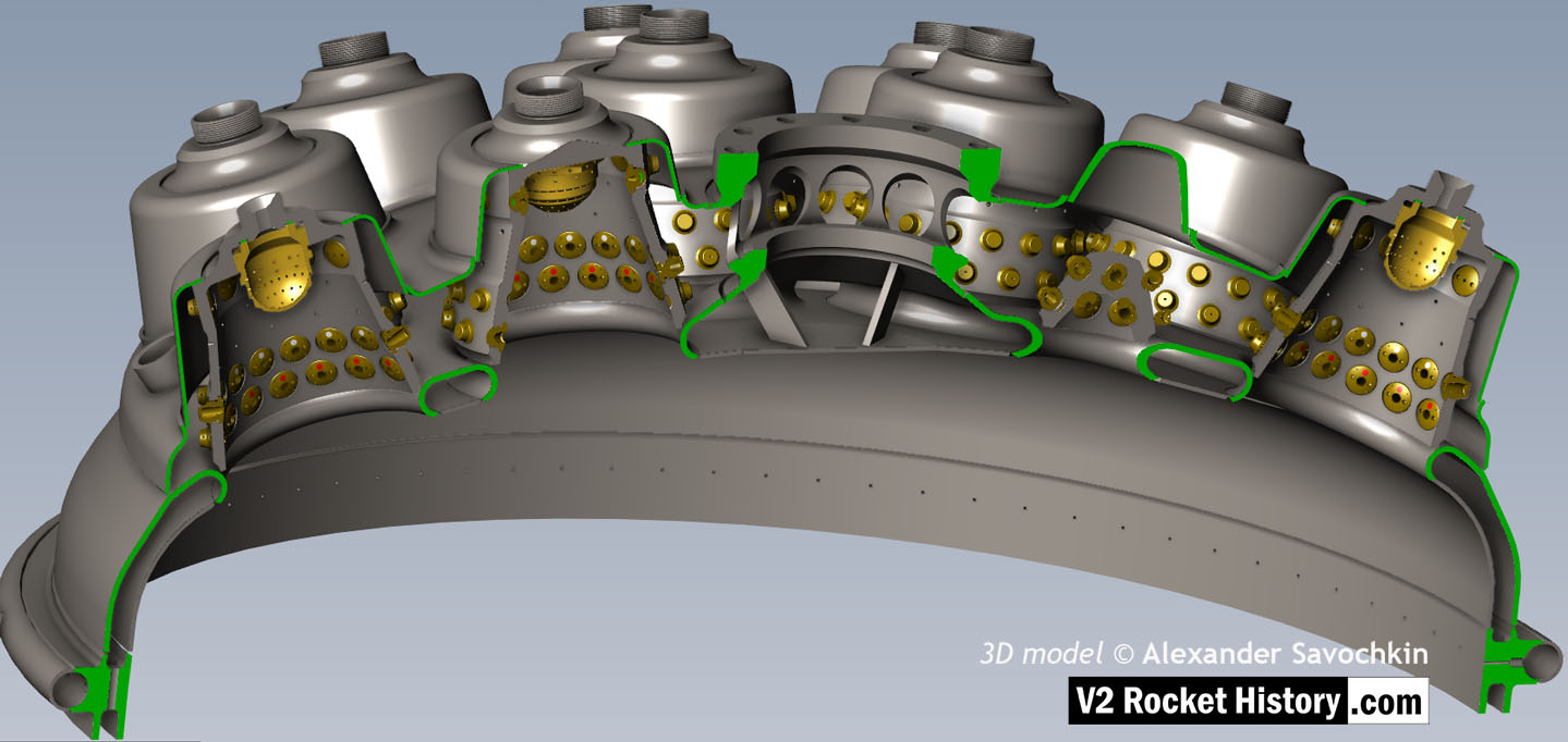
Here the 18-pot head model has been cutaway to show the fuel cooling and fuel delivery spaces. the cooling jacket layer can be seen in the lowermost area of the head – below the centrally positioned fuel valve seat, between each cup at the lowest point, and ruining down toward the first set of veil cooling pores and the topmost coolant distributor ring. Note that the veil cooling system does not communicate with the regenerative cooling jacket and has its own feed pipes drawing fuel from the head injector space and not the cooling space. Visible immediately above the valve seat are the large connecting holes that allow fuel to flow from the inlet manifold and cooling jacket to the injector space after the head fuel valve is released to be opened by the turbo-pump supply pressure. 3D model by Alexander Savochkin

Album: Anatomy of the V2: 18-pot injector head

Categories: Anatomy of the V2 Combustion

Tags: #Combustion and injection #chamber cooling

No Picture

18-pot Cutaway 1

18-pot Cutaway 1

Liquid propellent (LOX and fuel) diffuser cup, showing three rings or echelons (A,D,& E) of brass injector inserts as well as two rows of drilled fuel feed holes. The LOX spray head is shown in the centre. Note the simple ‘shower head or watering can’ design of the LOX diffuser. A sealing washer can be seen fitted between the LOX diffuser and the steel cup. 3D model by Alexander Savochkin

Album: Anatomy of the V2: 18-pot injector head

Categories: Anatomy of the V2 Combustion

Tags: #Combustion and injection #chamber cooling
No Picture

Jet from 2mm drilled fuel feed hole

Jet from 2mm drilled fuel feed hole

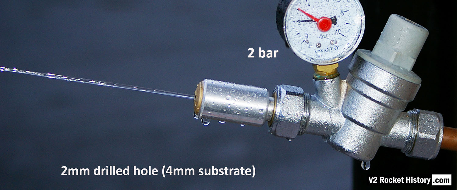
Each burner cup of the V2 rocket engine injector system has forty-four brass inserts, but each cup also has twenty-four 2mm diameter plain holes, 30 deg apart, drilled into the cup’s central wall. To mimic this for testing purposes, we created a brass insert that has a base with just a 2mm central hole. The base is sized to be consistent with the 4 to 5mm cup wall. V2RH image

Album: Testing fuel injectors

Categories: Combustion

Tags: #V2 Missile relics #Propellent injector system #Combustion and injection #Test procedures