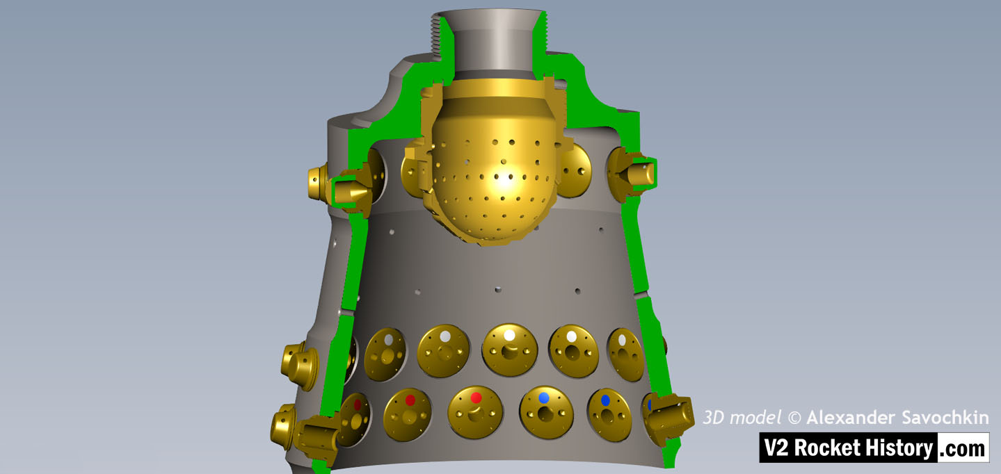
Lower section Fuel And LOX Diffuser Cup Cutaway 2
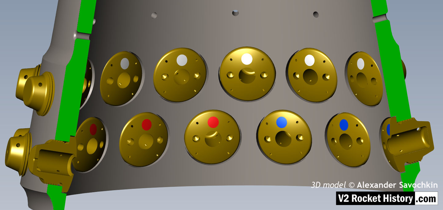
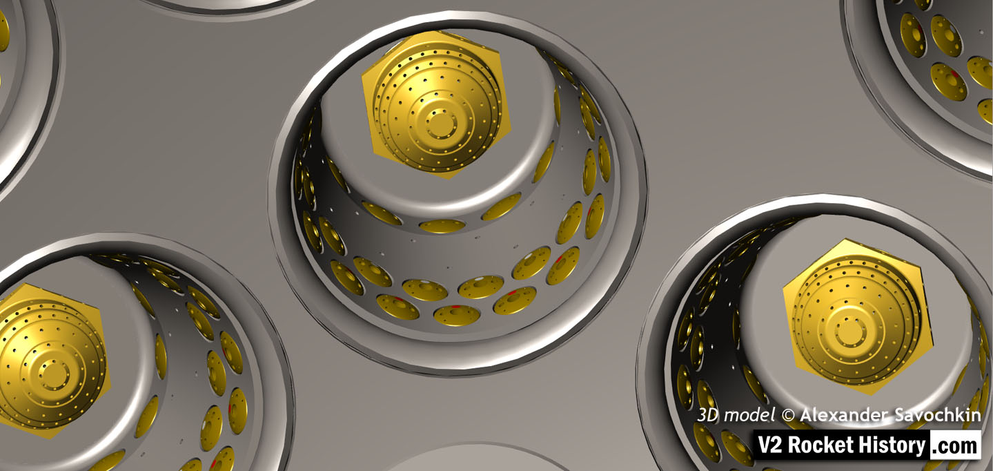
This images shows a cutaway of a burner cup from outer Ring I of the injector head and shows injector insert eschelon D, & E as well as one row of drilled feed holes. Three fuel injector insert types can be seen: Top D, = 3303D (white), lower E, = 3304D (red), and E, = 3305D (blue). 3D model by Alexander Savochkin
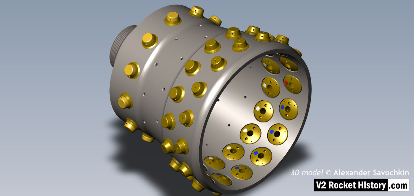
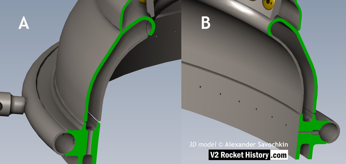
Album: Anatomy of the V2: 18-pot injector head
Categories: Anatomy of the V2 Combustion
Tags: