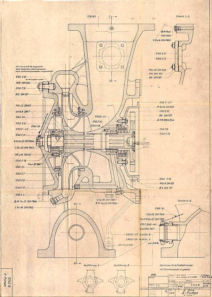
Turbopump parts and relics
This library contains material related to the A4-V2 turbo-pump sub-assembly including the steam generation plant. Including original photos, images of relics and documents.
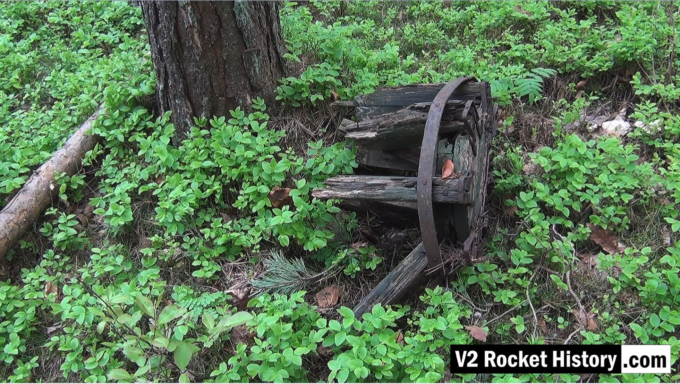
Wooden carboy frame from WW2 (possibly used for transporting small quantities of corrosive and dangerous liquids employed in the V2 steam plant, (such as T-Stoff) laying among trees 190m East of F1 in a location used as an emergency rail freight loading area to F1 due to damage caused by US air raids in August 1944.
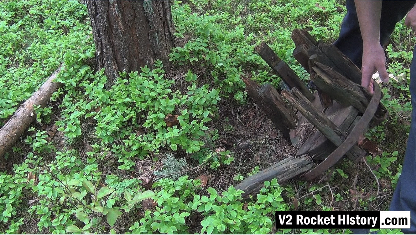
Wooden carboy frame from WW2 (possibly used for transporting small quantities of corrosive and dangerous liquids employed in the V2 steam plant (such a T-Stoff) laying among trees 190m East of F1 in a location used as an emergency rail freight loading area for F1 due to damage caused to rail track by US air raids in August 1944.
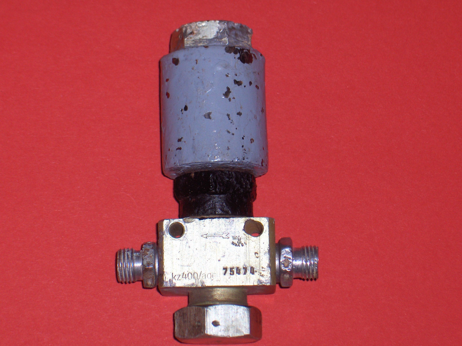
Solenoid electro-magnetic air valve. The This valve type is used numerous times to control equipment in the V2 missile. Variations of this electrically activated valve can be used to control high pressure air or fluids.
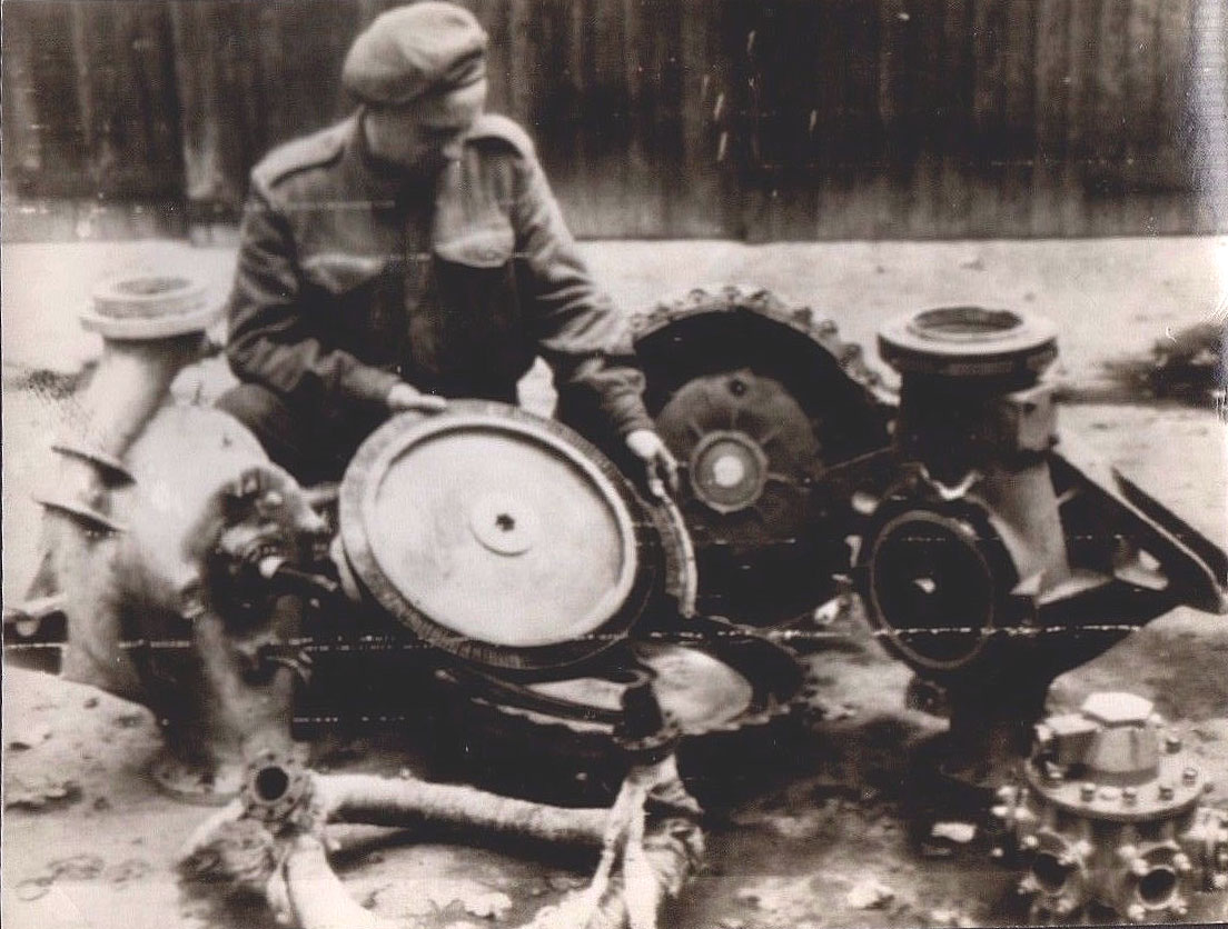
Image shows allied soldier examining remains of V2 rocket turbo-pump after impact. The soldier is holding the steam turbine rotor – the large size of this part is well shown in this photo. The still lagged steam inlet manifold can be seen in the left foreground and the LOX outlet manifold (and valve, topmost) can be seen in the lower right corner.
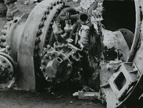
Picture shows tubo-pump debris from impact site. LOX manifold clearly seen (3 in 1 outlet pipes, upper center of image – the one to its right, 2 o’clock position, and left, 11 o’clock position are both broken off).The LOX flow electric control valve is also well displayed in this image (LOX valve head is slightly low and left of center, part nearest camera). The electrical connection to the LOX valve has broken away leaving its empty socket pointing upwards and to the right.
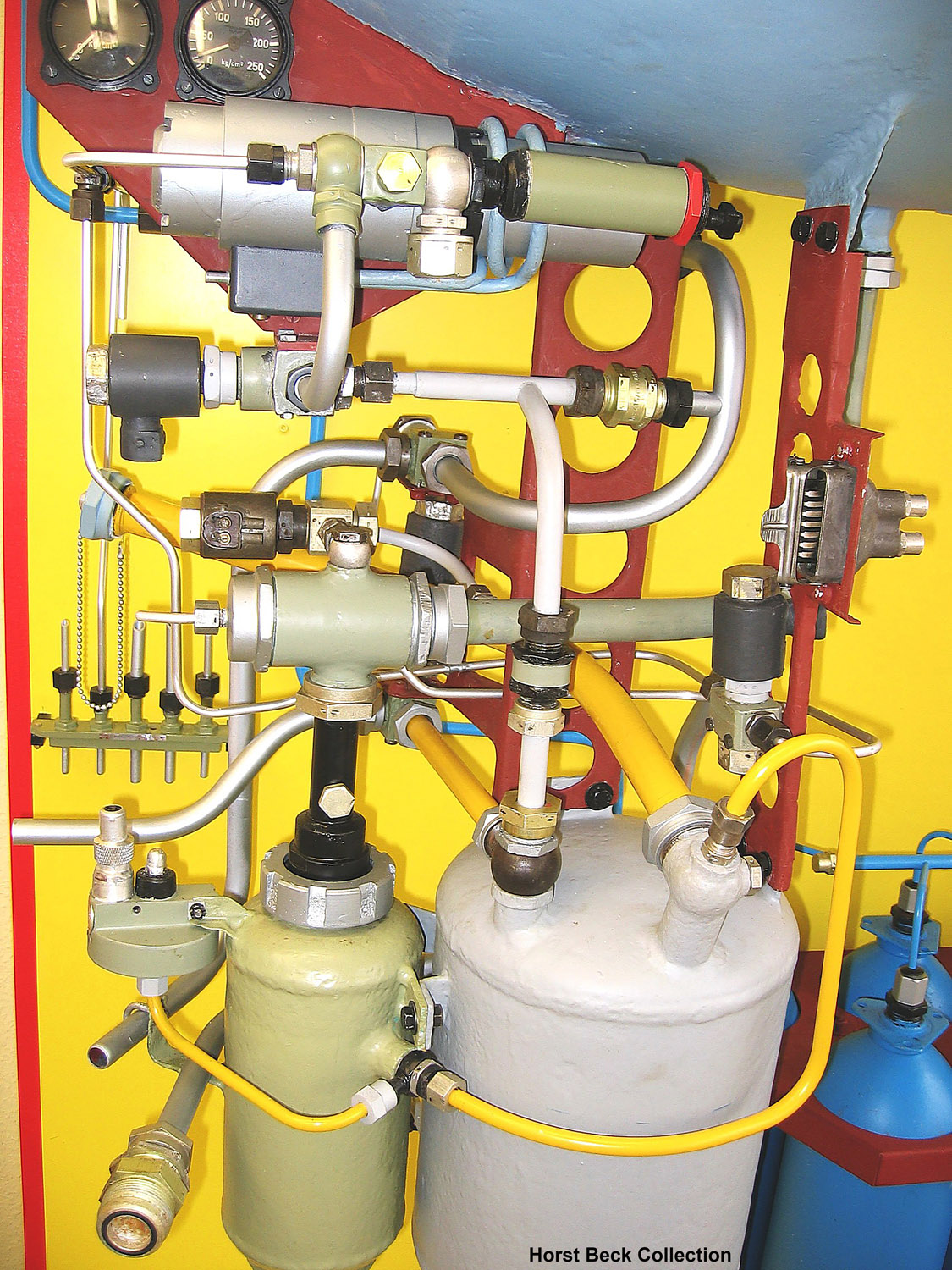
A4 missile steam generator detail. This excellent presentation was rebuilt from original refurbished parts by Horst Beck. See our video article The V2 Rocket Turbo-Pump for a technical exposition of the parts shown in this photo. Image courtesy The Horst Beck Collection
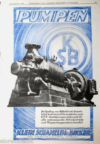
Klein Schanzlin & Becker electric centrifugal-pump advert.
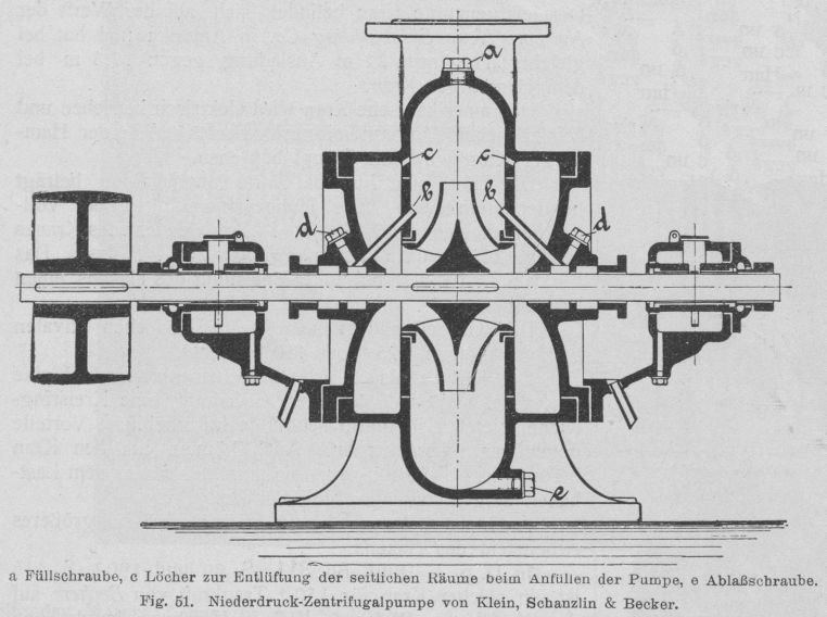
Early belt powered centrifugal pump by Klein Schanzlin & Becker. This schematic shows an early 20th century centrifugal pump designed and manufactured by KSB. The drawing appears to show auto-purge pathways at points marked C as well continuous lubrication pathways at B. Both of these important ideas would later feature in the propellant pump of the A4-V2 missile.
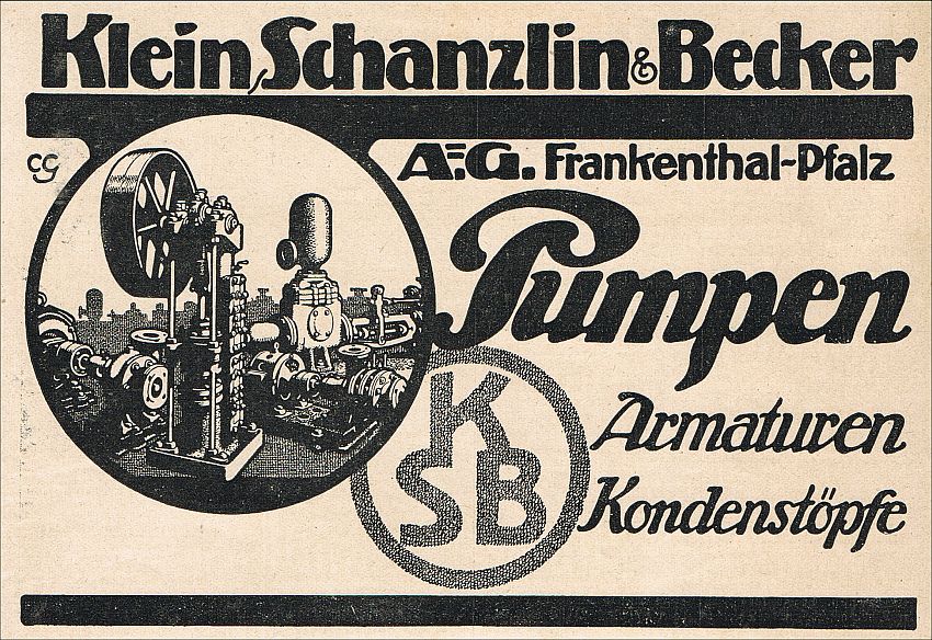
Trade advertisement for Klein Schanzlin & Becker (KSB supplier code ebb). KSB were the primary contractor for A4-V2 missile’s steam turbine driven dual propellant pump system.
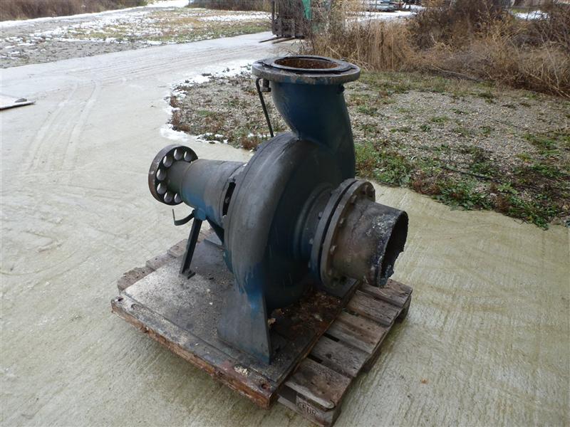
Large industrial volute case centrifugal pump by Klein Schanzlin & Becker. This image highlights the ‘genetic’similarity and family resemblance between KSB’s current and historical product range and the visible features of the A4-V2 missile Turbo-Pump (TP). Apart from the general shape of the cast spiral-volute case and its connection flanges, the ‘soft’ shaft connection (disk with holes on the extreme left of the pump) is very reminiscent of the semi-flexible shaft connection point linking one side the steam turbine rotor shaft to the shaft carrying a propellent pump rotor seen in the A4-V2 missile TP. Family photo? Industrial volute case centrifugal pump by KSB
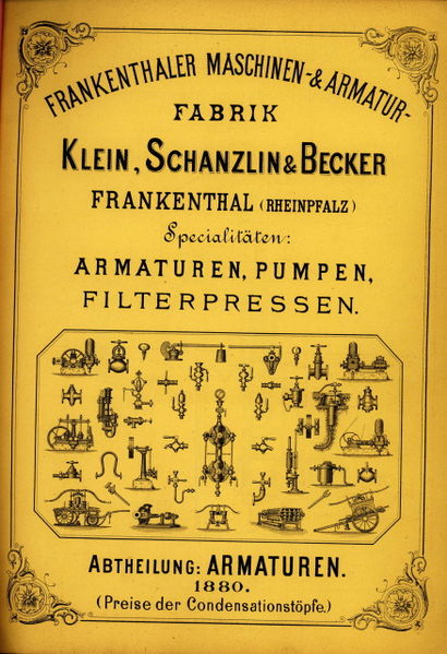
Cover of catalogue published in 1880 showing the KSB product range
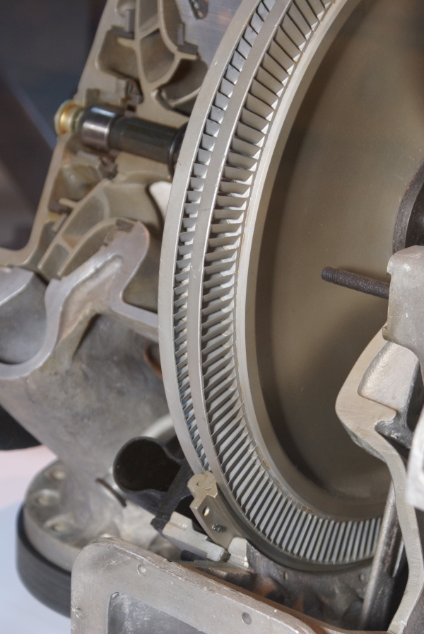
This image shows a cutaway of an A4-V2 turbo-pump. The section reveals the Curtis type 2-stage steam-turbine rotor and you can also see part of the stater inserted between the blades (bottom middle) and the adjacent steam distribution pipe (black open pipe on stater’s immediate left). Top left, a centrifugal pump rotor can be seen – cut through, it shows a multi-splined shaft running through the centre, simple bearing and end-cap.
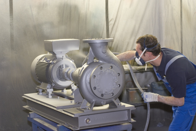
Electric industrial volute case centrifugal pump by Klein Schanzlin & Becker. This image highlights the ‘genetic’similarity and family resemblance between KSB’s current and historical product range and the visible features of the A4-V2 missile Turbo-Pump (TP). Assembly is shown being spray painted.
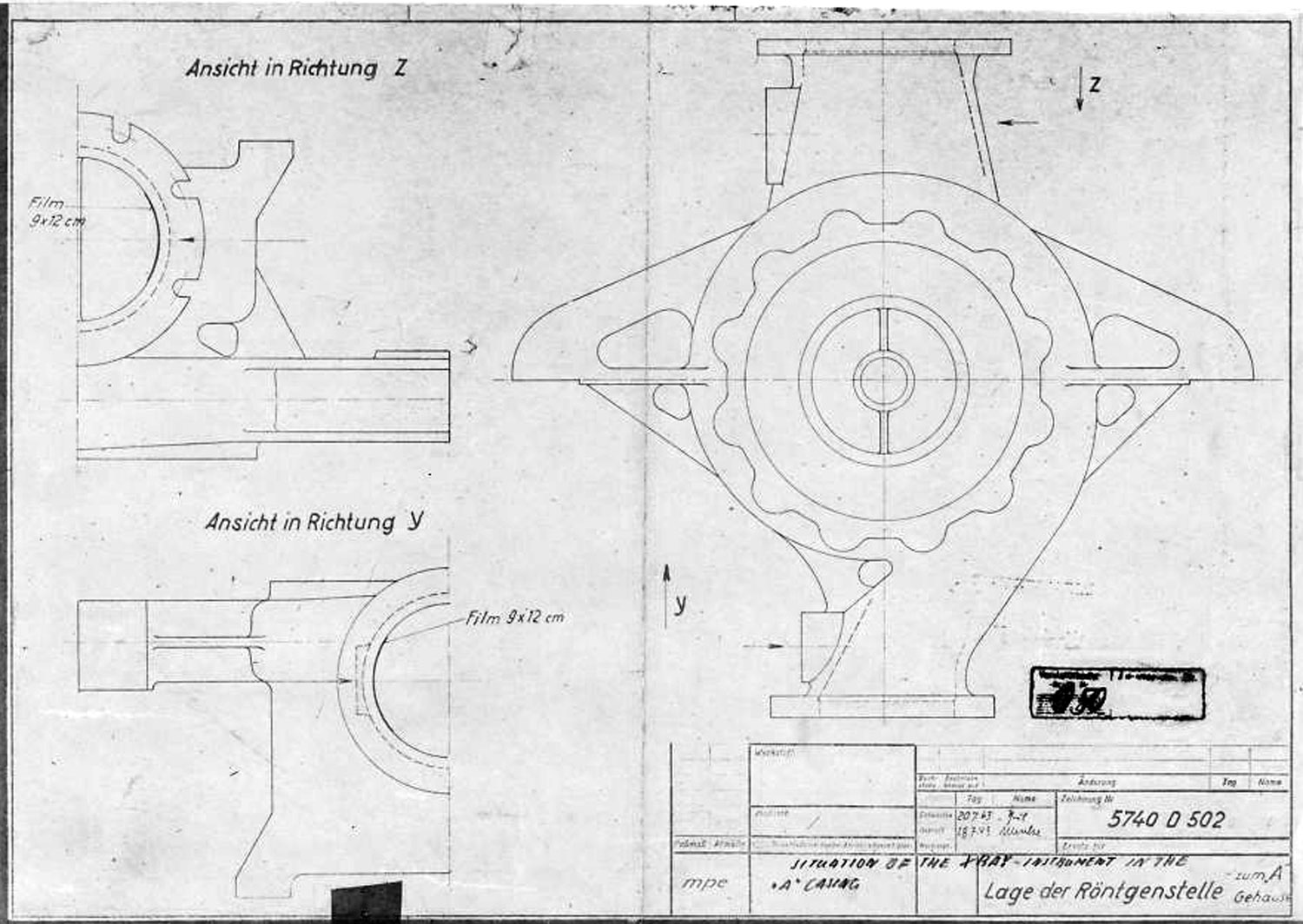
A Stoff (liquid oxygen) pump casing diagram showing stress points that require X ray quality control photography before use. The diagram shows the specific locations where photographic film is to be placed for X-ray analysis.
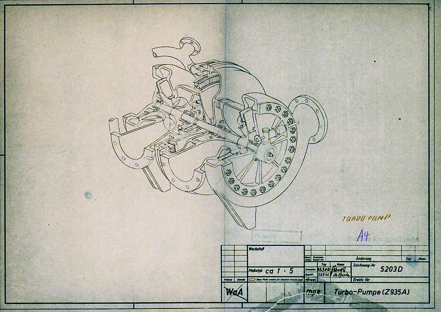
In this diagram the V2 Turbo-pump is shown in a cutaway presentation and rotated 90 degrees counter clockwise. The B stoff (fuel) pump is nearest the viewer – the over-speed device can be seen on the B stoff pump’s case end-plate. The low pressure inlet ports our shown to the left, and high-pressure outlet ports are on the right. The steam distribution manifold can be seen at the furthest point from the viewer – the steam inlet pipe flange can also be seen. The feed pipe from the steam generator attaches to thus flange.
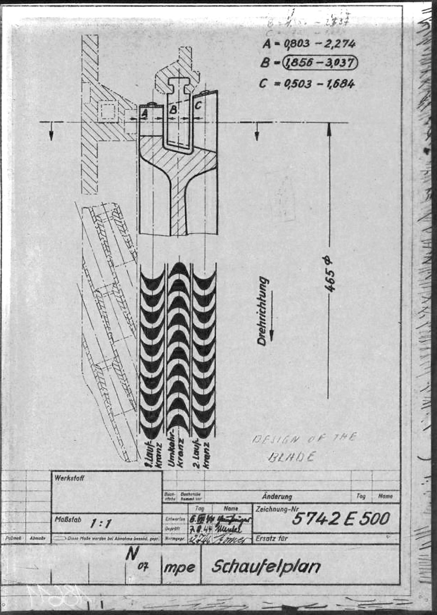
This mpe* drawing from 1945 shows the individual steam buckets or blades (labeled A and C) mounted to the rim of the rotor disk. As well as the fixed (i.e. stationary) stater blade B, positioned such that blades A & C can pass either side of it. The steam expansion is well shown by the increasing surface area of the blades from A to C, and growing larger, from left where the high pressure super heated steam enters the turbine, to right where it exits the blade pathway and passes in to the exhaust outlet. The lower graphic shows the way the super-heated high pressure steam is passed from the initial A blade and deflected by the reversed B stator blade for its energy to to be harvested for a second time by the C rotor blade. * mpe is the secret three letter armament code for Karlshagen, Werk Nord (North Works).
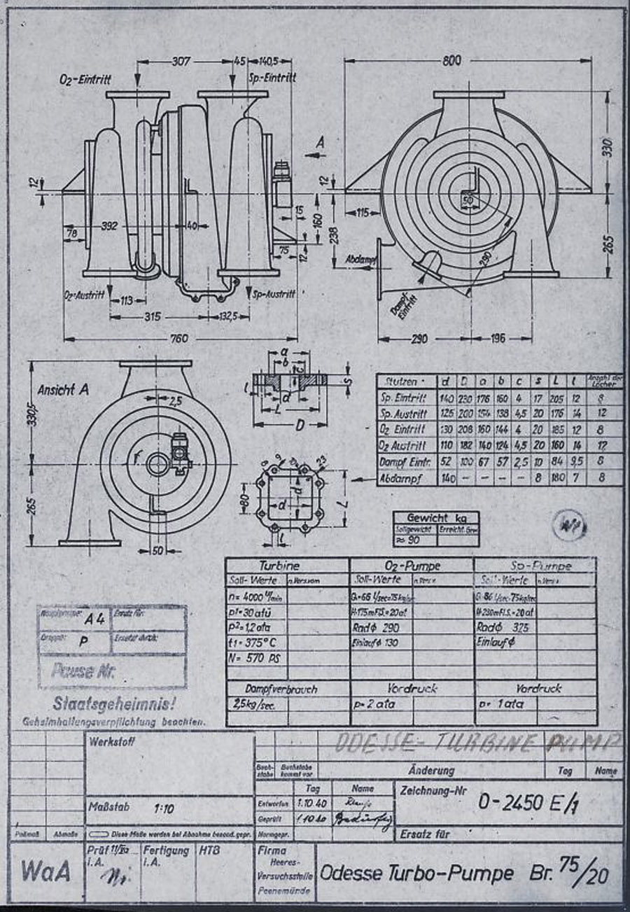
This HVP technical drawing from October 1940, shows a proposal from the Oddesse company – the full title of this company is KLEIN SCHANZLIN ODDESSE GmbH. Klein, Schanzlin & Becker A.G. (waffenamt code: ebb) took over Oddessa in 1929 and the company became formally known as KLEIN SCHANZLIN-ODDESSE GmbH (code ebc) in 1939. (NB: The company name has nothing to do with a similar sounding place name Odessa. The Oddesse trading name was formed from the partnership of English engineer Oddie, and German businessman Hesse.). The dual centrifugal turbo-pump shown in the drawing is a variant of a high pressure fire-fighting pump manufactured by Oddesse. Note the off-center outflow ports – not also that the outlet flanges are still level at this stage. Note also the incorrect spelling of the company name in the details panel lower right. (Digipeer.de image)
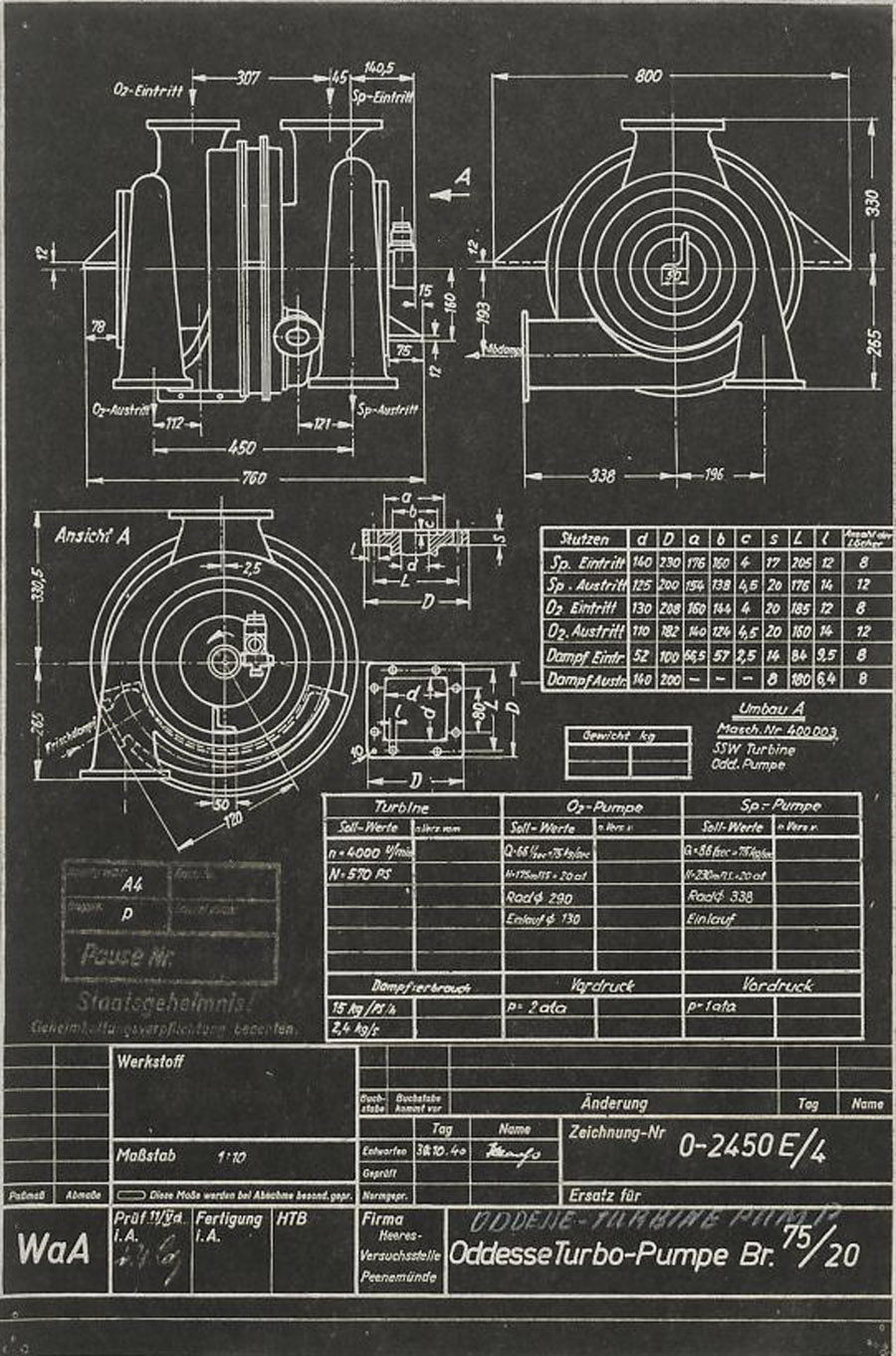
Another HVP technical drawing from later in October 1940, shows further data from the KLEIN SCHANZLIN ODDESSE (ebc) company A4-V2 turbo-pump project. See previous image for company details. The dual centrifugal turbo-pump shown in the drawing is a variant of a high pressure fire-fighting pump manufactured by Oddesse. Note the off-center outlet ports. Note also the corrected spelling of the company name in the details panel lower right (see previous Oddesse image) and the small note below the top table that indicates that the pumps are from Oddesse (ODD) and the turbine from a company indicated as SSW. (Digipeer.de image)
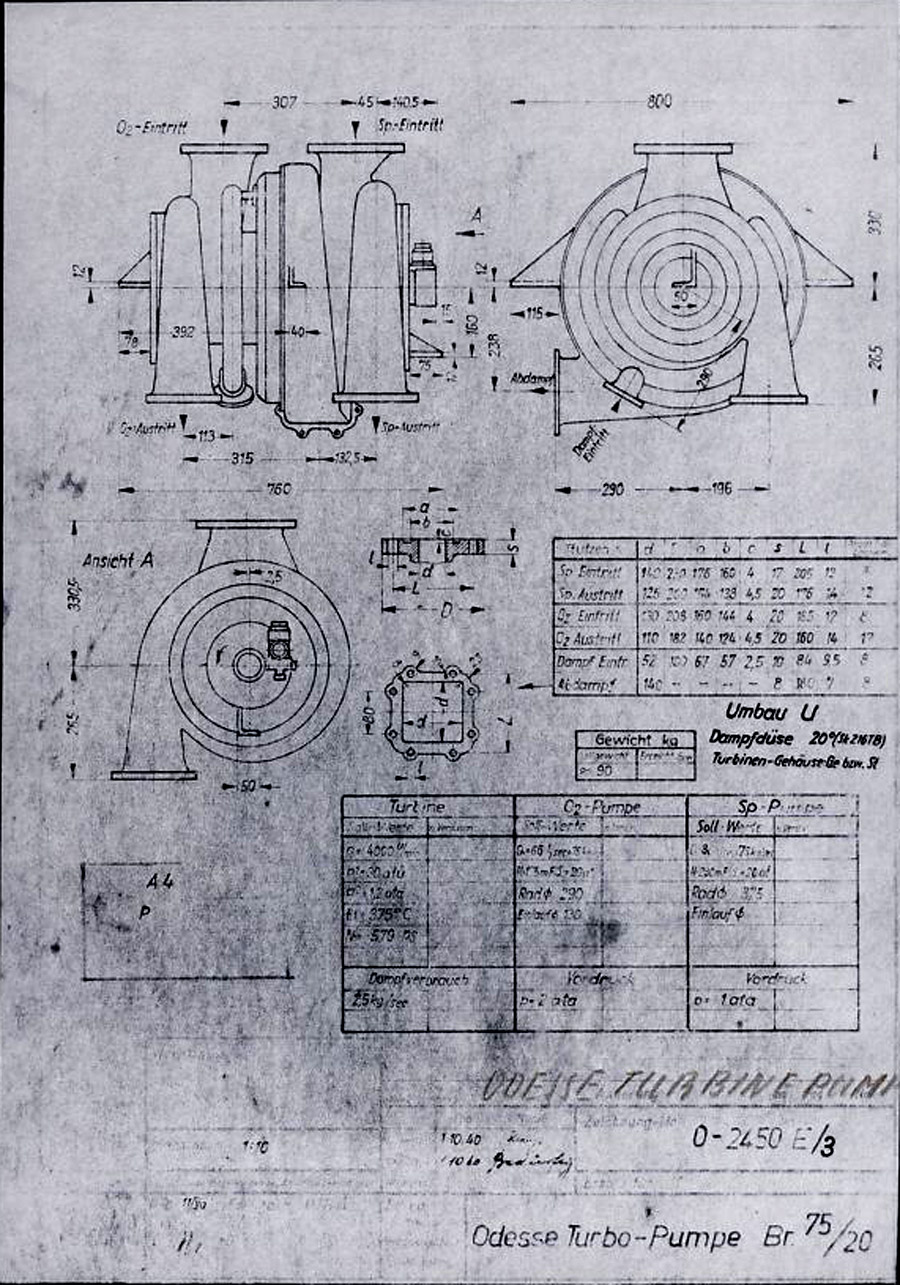
Signatur FA 014/21241 (Digipeer.de image)
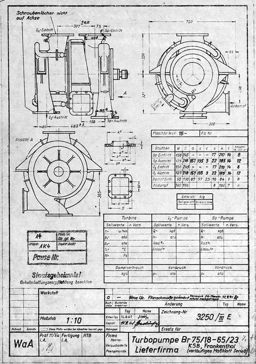
V2 rocket turbo-pump preliminary dimension sheet for O series, drawing. Many of the final elements of the turbo-pump design can be seen in this ‘preliminary’ drawing and table form 1941. The word lieferfirma in the data box btm right mean supply company – and this is indicated to be KSB or Klein Schanzlin & Becker AG, Frankenthal. Signatur FA 014/14769
(Digipeer.de image)
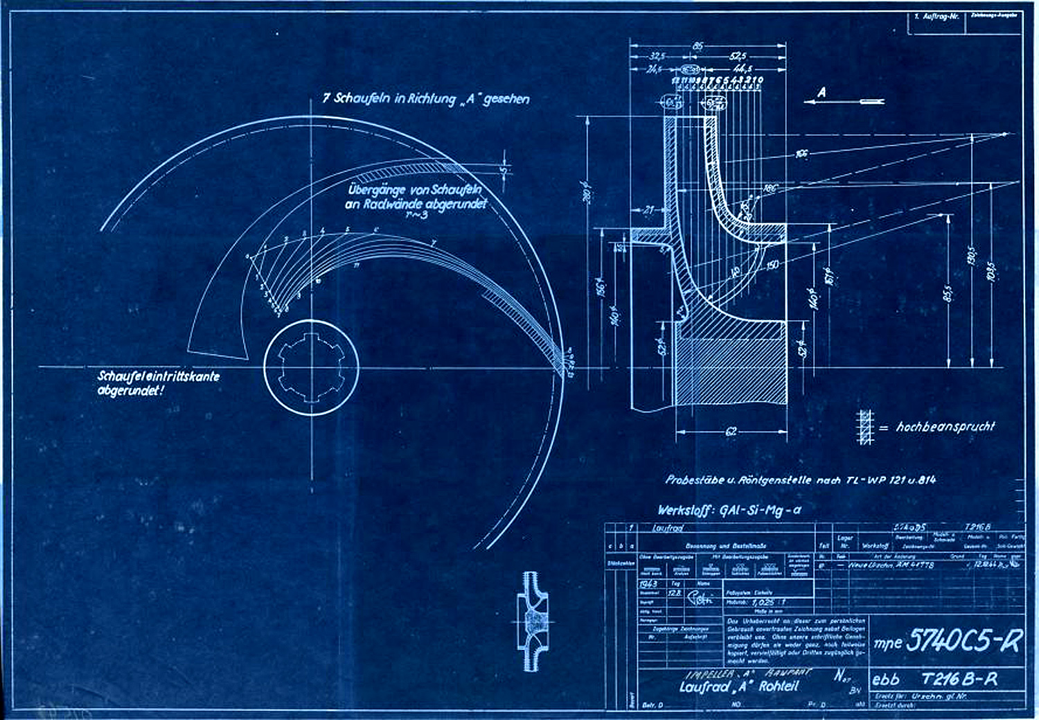
Centrifugal impeller for A or liquid oxygen (LOX) pump. The drawing originated in Aug 1943 and was superseded in December 1944. A key to the image hatching can be seen with the label ‘Hochbeansprucht’ which in English means Highly Stressed. Next to the drawing numbers two secret three letter armament codes can be seen indicating the ‘origination’ of the document. The top one mpe = Heimat Artillerie Park 11 (HAP or Army Artillery Range). The lower code ebb = Klein Schanzlin & Becker AG, Frankenthal.
Signatur FA 014/02542 (Digipeer.de image)
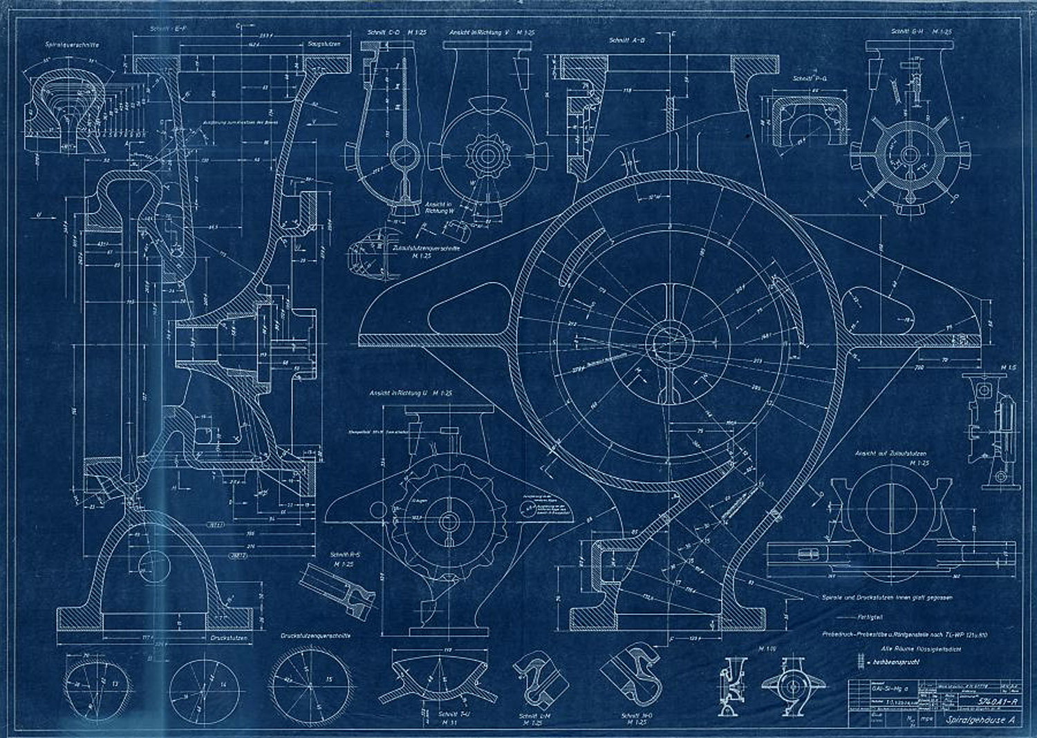
Signatur FA 014/02537
Abmessungen: 42,9×59,8

