

Archives: Gmedia Albums
The Enigmas
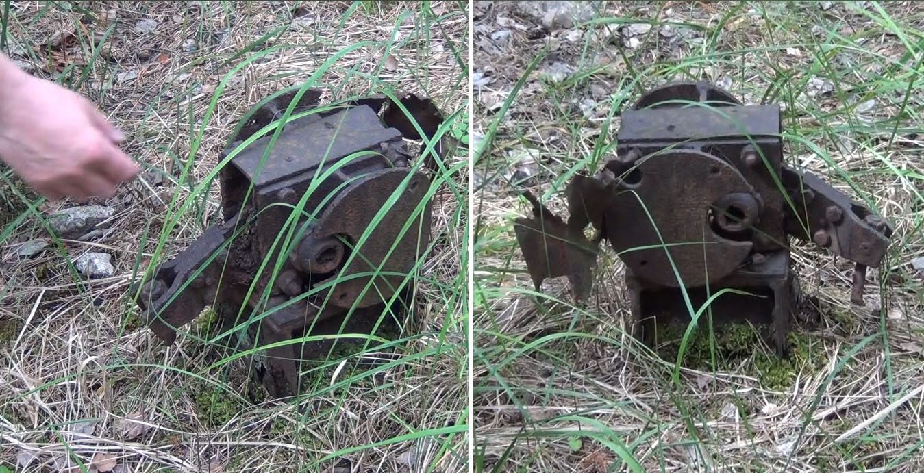
Unknown repair workshop (IW) mechanism
Unknown repair workshop (IW) mechanism
We think this relic, welded to a heavy gauge H beam, may be a points switch for a railway line. But do you know what it is, and what it did? If you do, please tell us.
| Album | The Enigmas |
| Category | Mystery part |
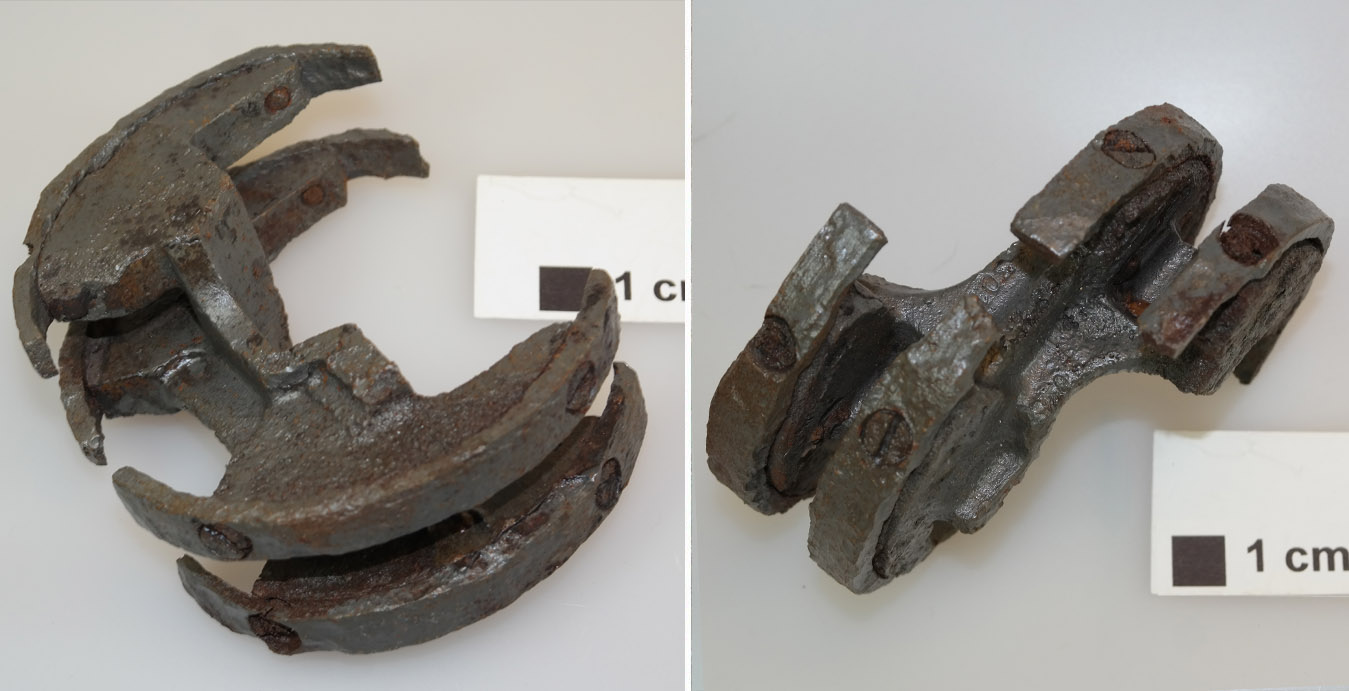
Unknown helical part
Unknown helical part
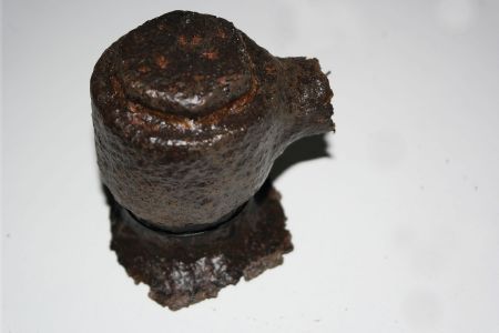
This part has a helicoid or screw shape, it seems that it might have been designed to screw into a pipe of some kind. But do you know what it really is, and what it did? If you do, please tell us.
| Album | The Enigmas |
| Category | Mystery part |
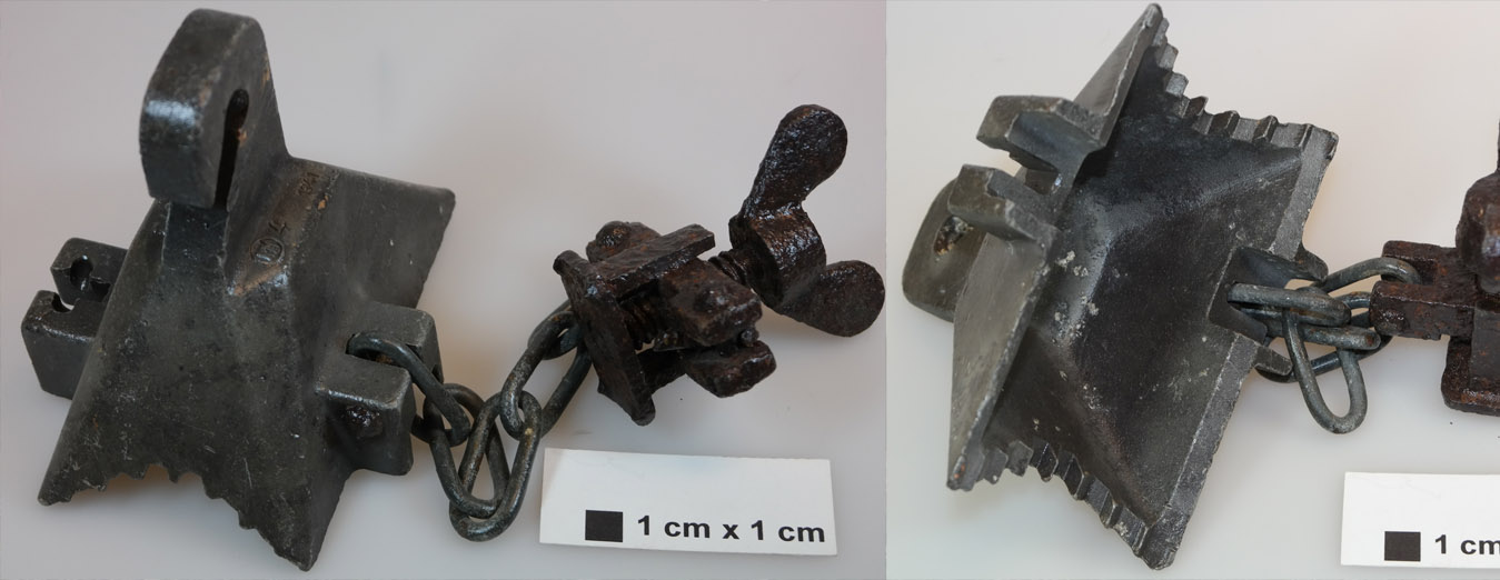
Chain and hook clamp – unknown use
Chain and hook clamp – unknown use
We know this is a clampy-chainy-hooky thing – but do you know what it really is, and what it did? If you do, please tell us.
| Album | The Enigmas |
| Category | Mystery part |
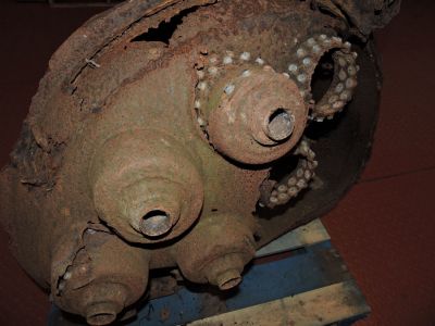
Close up of relic within IW near aisle 20
Close up of relic within IW near aisle 20
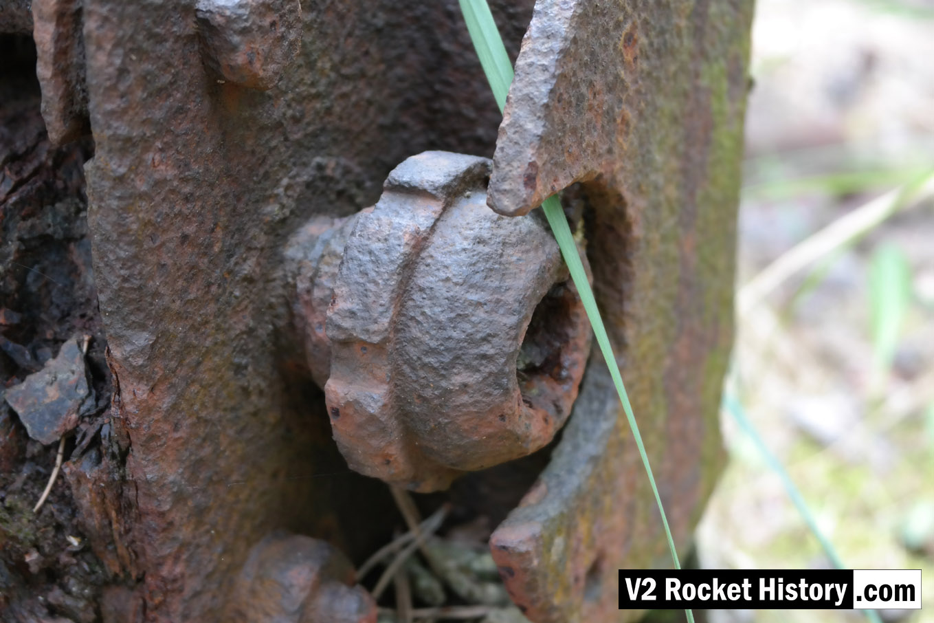
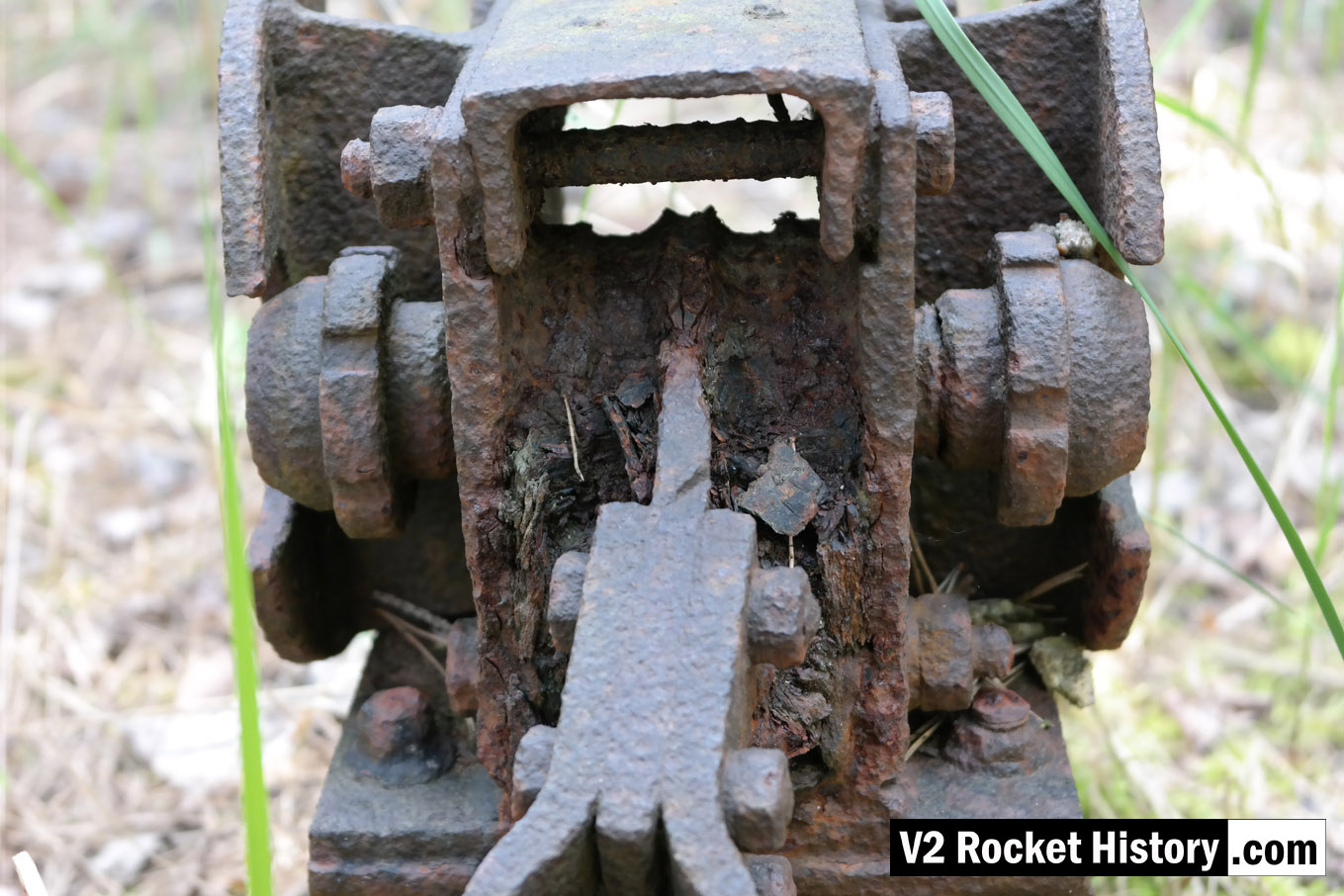
This is a close up of the mystery item, referred to on our Enigma page, found firmly anchored to the floor a few metres inside the east wall near aisle 20 of IW (near location of internal railway line).
| Album | The Enigmas |
| Category | Mystery part |
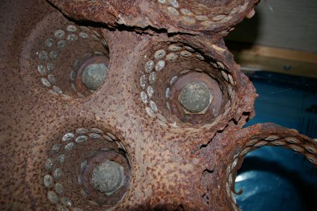
Close up of relic within IW near aisle 20
Close up of relic within IW near aisle 20
This is another close up of the mystery item showing the mechanism in more detail. It can be found firmly anchored to the floor a few metres inside the east wall near aisle 20 of IW (near location of internal railway line). See map below for location.
| Album | The Enigmas |
| Category | Mystery part |
F1: Fertigungshalle Eins
IW and F1 on 19th August 1943
IW and F1 on 19th August 1943
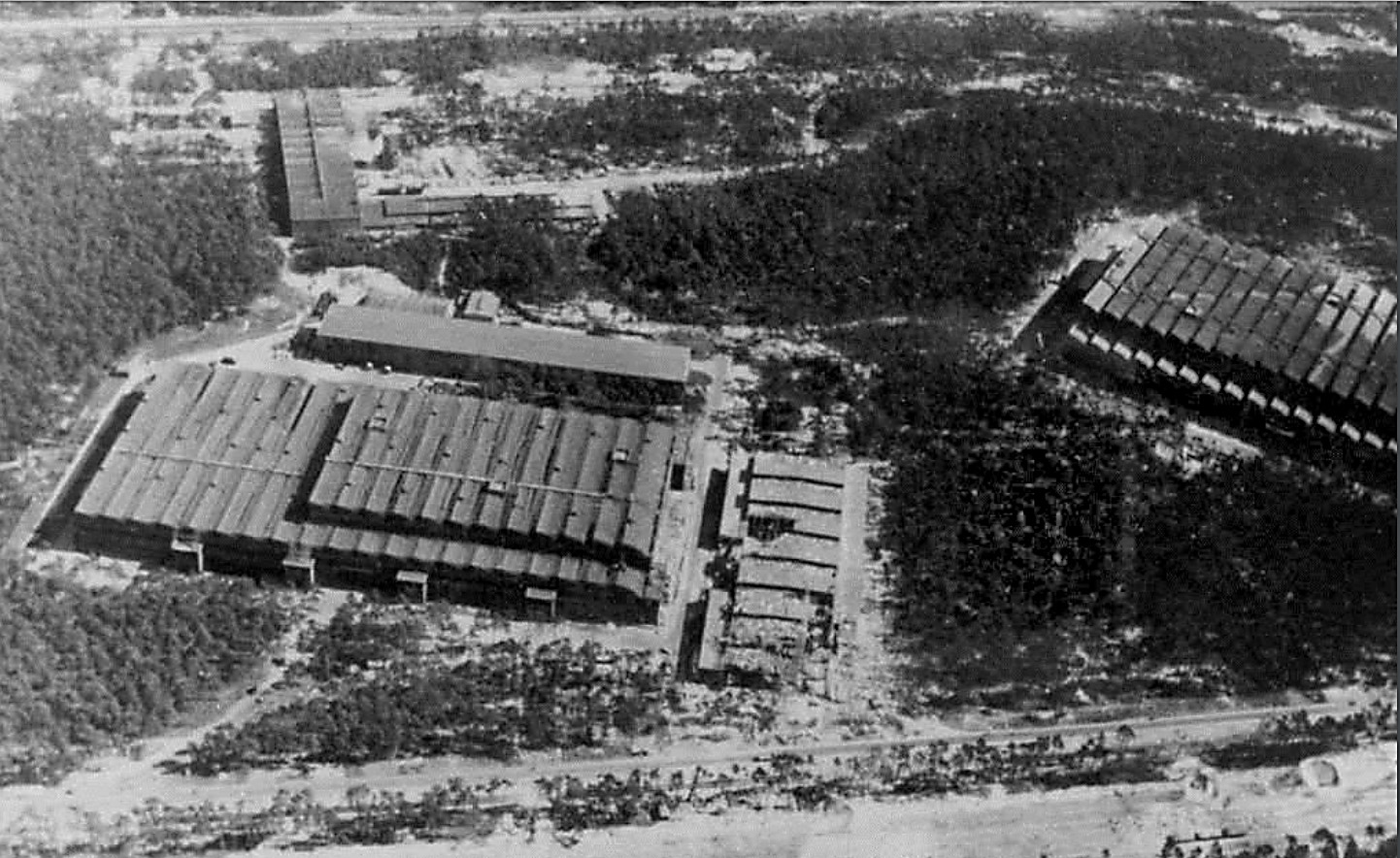
Photo showing Werk Süd with IW on the left and F1 on the right taken on 19th August 1943. The photo shows only light damage to the main halls, although F1 was actually hit at least 11 times, and hits to the separate single storey workshops to the right of the IW hall. The long storage (oil and paint?) shed above IW and the woodworking shop at the top of the picture appear undamaged. Anti-aircraft platforms (at least 3) can be seen on the roof of IW but that seem to be empty of guns. F1 shows two AAA platforms (there was at least 3 at this stage and maybe more) and they may have guns installed. General W. Dornberger mentions defensive AA artillery fire from the from the roof of F1 in his 1952 book V2 (1954 in English).

The IW ‘oil shed’ loading stage
The IW ‘oil shed’ loading stage
The remains of the a rail and truck loading stage located in the long oil storage shed adjacent to the IW repair and maintenance hall (IW R&MH) are substantial and have intact steadying chains along the south edge of the platform. There are access steps to the west and east ends (east shown). This loading stage was originally furnished with a wooden platform.

Bomb damaged F1 factory 1945
Bomb damaged F1 factory 1945
Bomb damaged F1 factory 1945. The huge V2 rocket factory shown badly damaged by air attack at the end of the war in May 1945
Fertigungshalle Eins (F1) after the RAF raid of 1943
Fertigungshalle Eins (F1) after the RAF raid of 1943
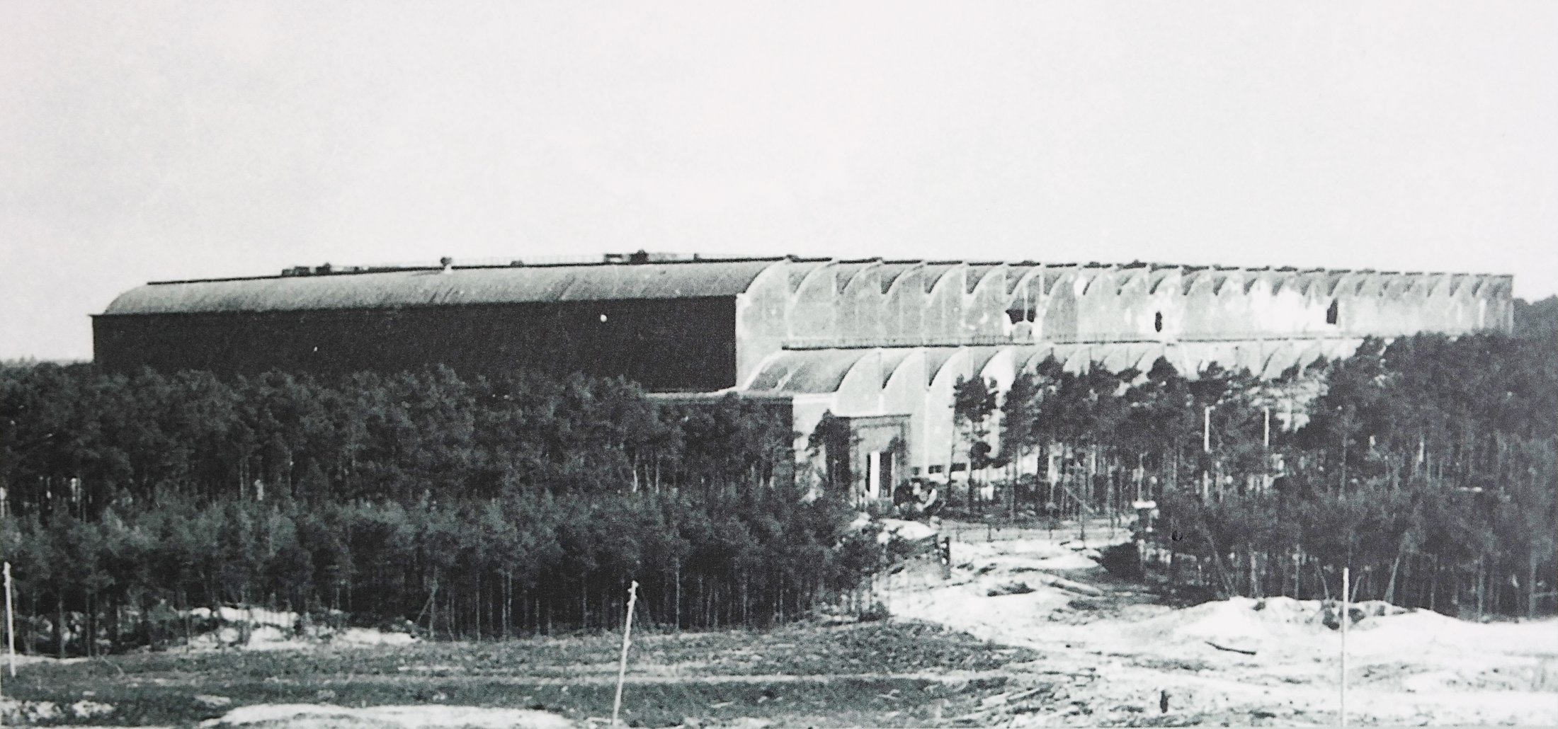
A rare photo of the giant F1 production hall taken not long after the RAF raid of 17/18th August 1943. F1 was a forced labour camp with at least 600 prisoners living within the factory and at least eleven were killed in the raid. Parts of the electrified barbed wire fence can be seen close to the factory building, in the clearing in the middle of the photo. Two anti aircraft gun emplacements can be seen on the roof at the front of the building. Holes in the side walls of the upper vaults can be seen as well as the damage to lower vaults 9 and 10 (counting from left) from a direct hit in this region. Also of note are the numerous guy ropes, attached to the upper roof of the front of the building – and running down towards the trees, that are just visible in the photo. These may be supports for camouflage netting that was in the process of being fitted (by prisoner gangs) just before the raid. The work was never completed.
Peenemünde: Werk Sud attacked by US bombers August 1944
Peenemünde: Werk Sud attacked by US bombers August 1944
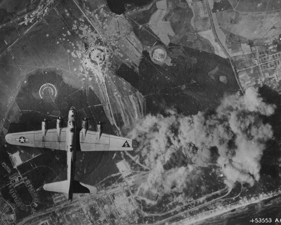
Peenemünde: Werk Sud attacked by US bombers August 1944 in a daring daylight raid. The two large halls F1 and IW in the lower middle of the photo are under direct attack and smoke can be seen originating from both buildings. Although the August 1944 raids did little to interrupt the volume manufacture of the V2, as virtually all manufacturing and assembly of the missile had moved to central Germany, the raids did bring to an almost complete halt the last small amount of manufacturing work still competed in the giant halls of Werk Sud.
Equipment bays

V2 rocket fuel injector inserts
V2 rocket fuel injector inserts
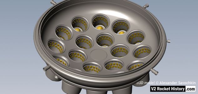
V2 fuel injector inserts 3303D, 3304D, and 3305D for injector pot echelons D and E. Photo shows swirl inlet aperture size and position.The total number of each insert type is shown, each of the 18 pots carried a total of 44 inserts. An additional 24 feed holes were drilled into the burner cup, occupying two rows B and C having 12 holes each. V2RH image

Sample set 3303D inserts
Sample set 3303D inserts
Sample set of 3303D type fuel injector inserts that were found in Peenemünde in part of a group that were bunched together in a space about 300mm in diameter with the remains of packaging. They appear to be manufacturing samples and and some have been graded with numbers 1,2,3, as well as with red and white paint to show the burner cup echelon position (C or D). Five different manufacturers are represented in this group. V2RH collection image

Injector insert set detail with drawing codes
Injector insert set detail with drawing codes
Fuel injector inserts for production series 18-pot injector head. The top row shows the injector face, second row shoes the same types from the rear. The lowermost insert have been halved to reveal the cavity shape, orifice edge, inlet and cooling apertures. Note that the insert in column A, 2131E, is two piece construction, and pressed together for assembly (see additional photo). On test, the parts had to remain together under a separation force of 300kg.

V2 Fuel Injector 2131E
V2 Fuel Injector 2131E
V2 Fuel Injector insert: part code 2131E from injector pot echelon A (nearest to LOX spray head). The push-together two part construction of the insert is shown here. The two parts were pushed together in a specially shaped tool set that compressed the thin skirt on the female part into a recess cut into the male part. The failure test for this component required that the mated parts resist a separating force of 300kg. The two part design was dictated by the small size of the 2mm exit orifice and the funnel shaped introduction to the exit orifice. In the case of the other three standard inserts, the large 6mm exit orifice allowed a sub 6mm milling cutter, with a thin support shaft and a top chamfer, to be used in such a way that the area below the exit orifice could be undercut to create an injector cavity with a diameter larger than the 6mm entry point.

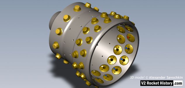
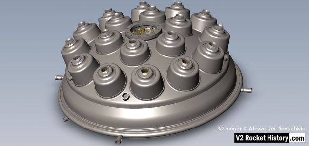
V2 rocket fuel and LOX injector pot
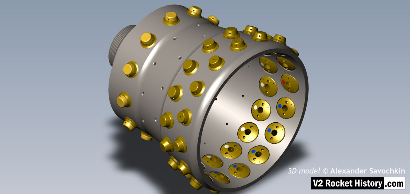
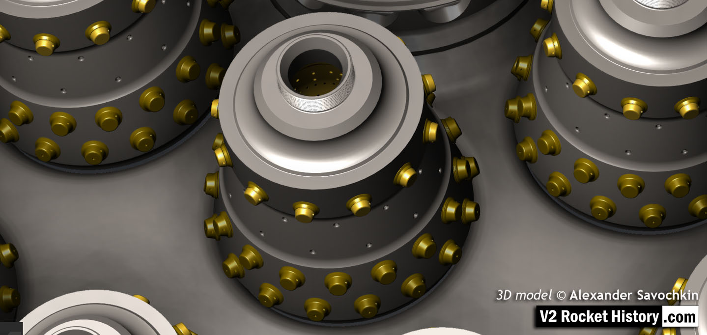
V2 rocket fuel and LOX injector pot
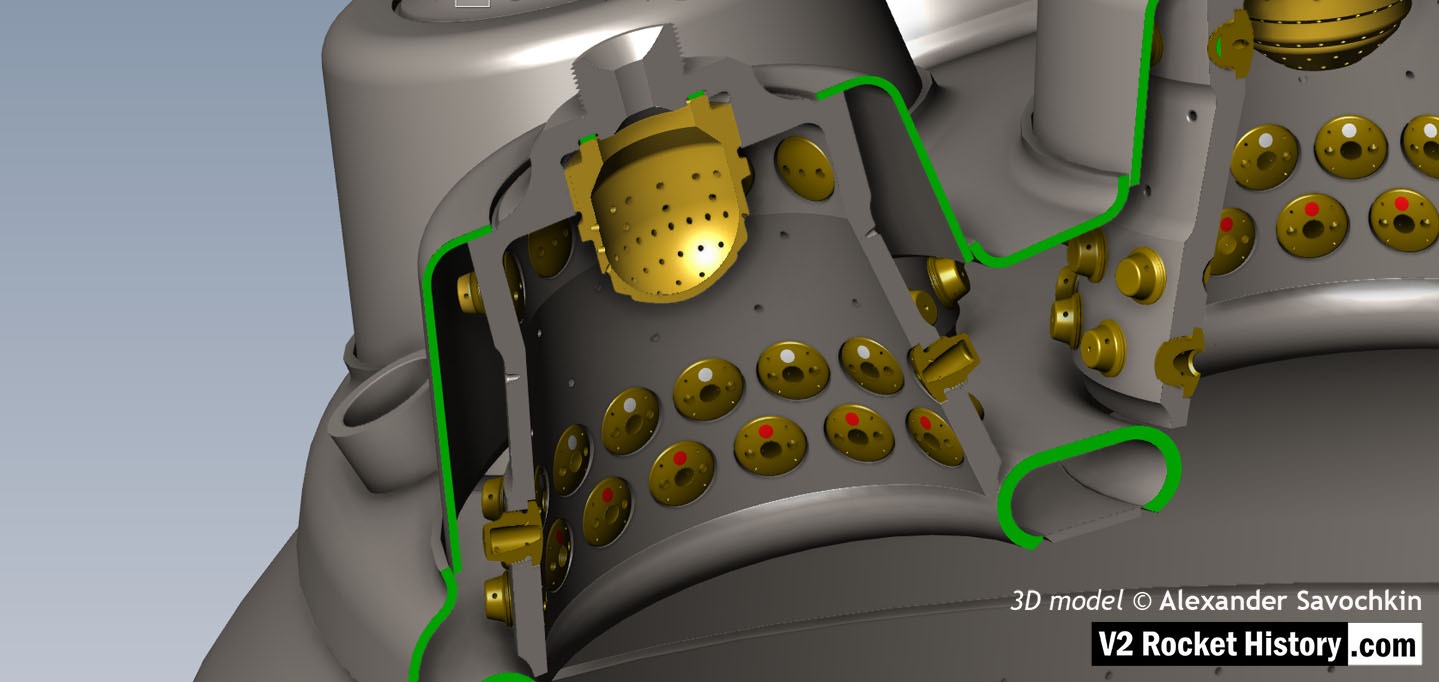
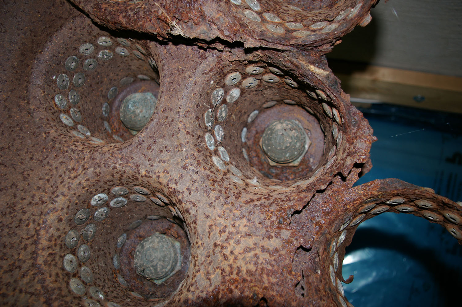
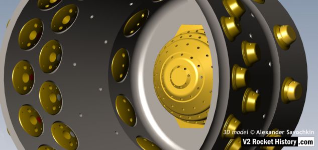
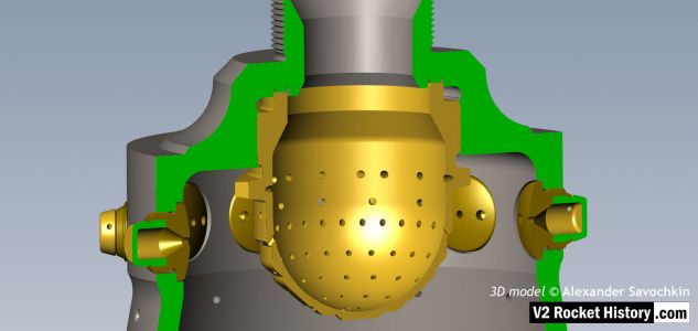
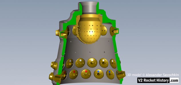
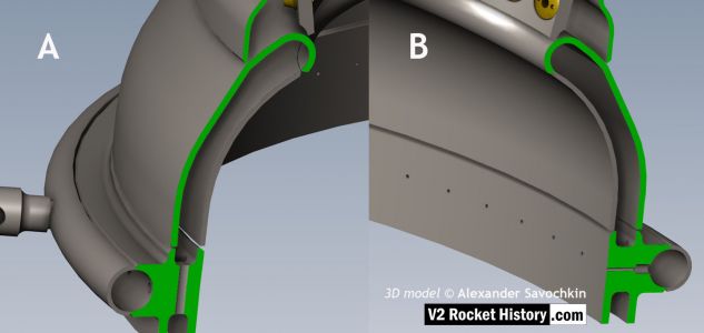
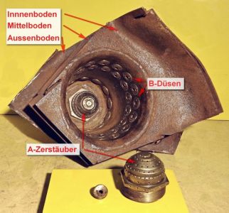
Cutaway section of fuel and liquid oxygen (LOX) injector pot. The exhibit shows the bell shaped thick inner wall of the burner with three tiers of fuel injector inserts (A,D, and E). The central copper alloy LOX spray injector is also well displayed in this image. The thin steel outer shell of the burner cup is shown and affords a good view of the head cavity that supplies fuel to the injector inserts – one A type injector is shown party cut through on the right, its rear portion showing inside the fuel cavity. V2RH image

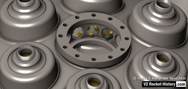
Section of fuel and liquid oxygen (LOX) injector pot
Section of fuel and liquid oxygen (LOX) injector pot
Cutaway section of fuel and liquid oxygen (LOX) injector pot. The exhibit shows the bell shaped thick inner wall of the burner with three tiers of fuel injector inserts (A,D, and E). As well as the two rows of plain drilled apertures B and C. The central copper alloy LOX spray injector is also well displayed in this image and shows the three letter armament code of the manufacturer (elr = H.K. Rudolf, Pilsen) and the 1943 date of manufacture on one face of the hex nut. Note the close proximity of the tier A injector inserts to the LOX injector. The spary from these injectors plays directly onto the lower section of the LOX spray head. This section of the burner cap had the lowest temperature and as a result tier A insert did nor require cooling pres. See associated picture. V2RH image

Fuel Injector insert showing aperture details
Fuel Injector insert showing aperture details
Standard fuel injector inserts for production series 18-pot injector head. Insert 1 (3304D/3305D) shows four thin wires demonstrating the angles of all four ‘cooling’ pores. Insert 2 (3305D/2131E) has two 1.3mm twist drill showing the edge bores for the gyroscopic swirl inlets. Insert 3 (3305D) shows another view of the cooling pore angle and origin. V2RH image

‘Einheitskopf’ Type 4B Injector head fragment
‘Einheitskopf’ Type 4B Injector head fragment
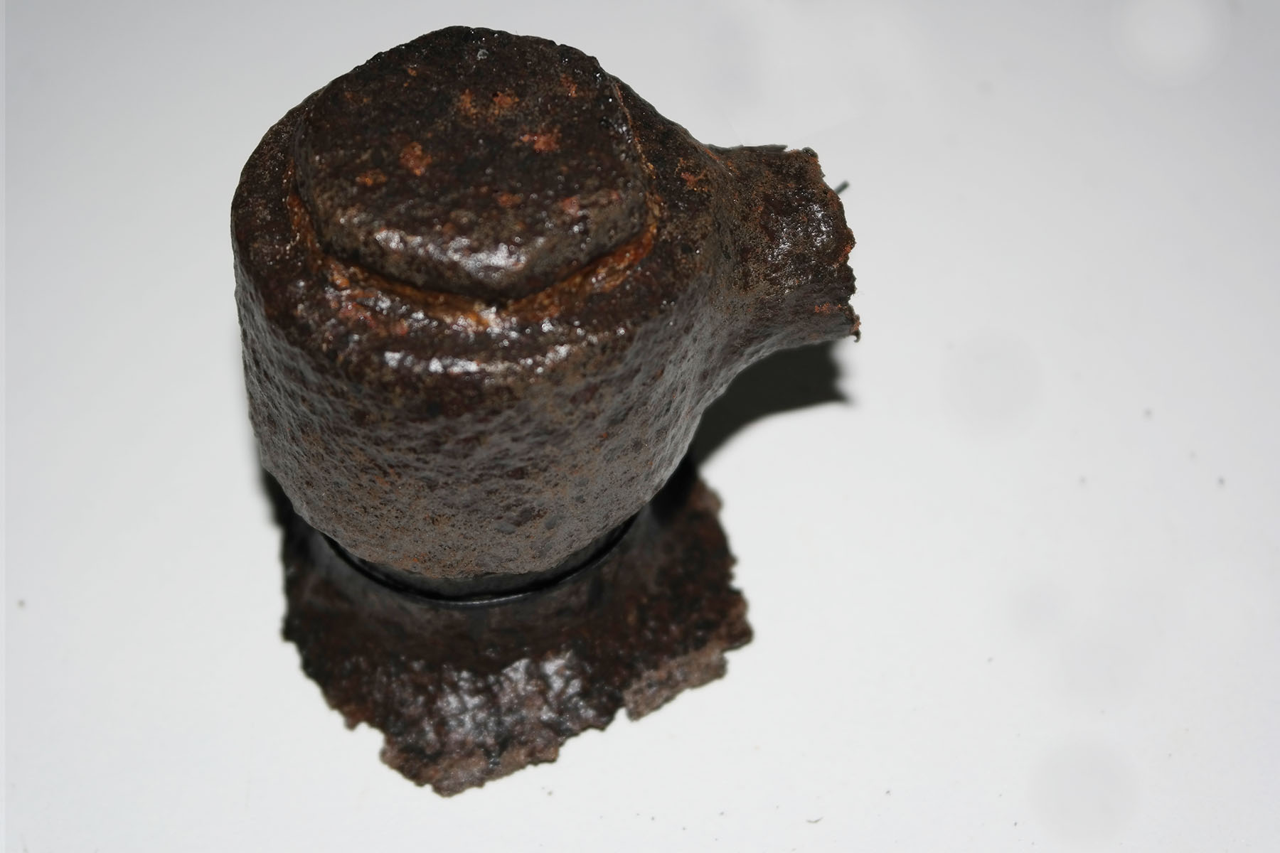
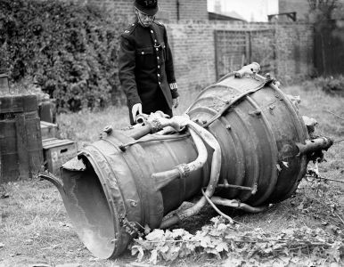
The injector head fragment shown here, is from an 4B 1000 kg thrust engine that was developed at Kummersdorf in 1938/39 by Dr Walter Thiel’s combustion research group. The fragment, clearly the remains of an explosion, was actually found in a scrap pile in Peenemüde but the engine was probably tested (and destroyed) at the Kummersdorf army testing station. V2RH collection image.

25-Ton aluminium injector pot from 1940/41
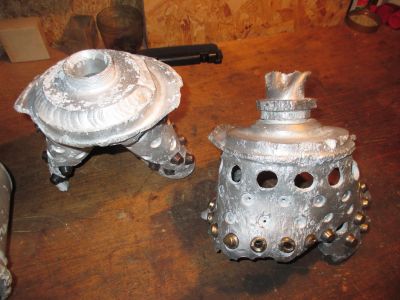
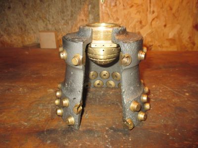
25-Ton aluminium injector pot from 1940/41
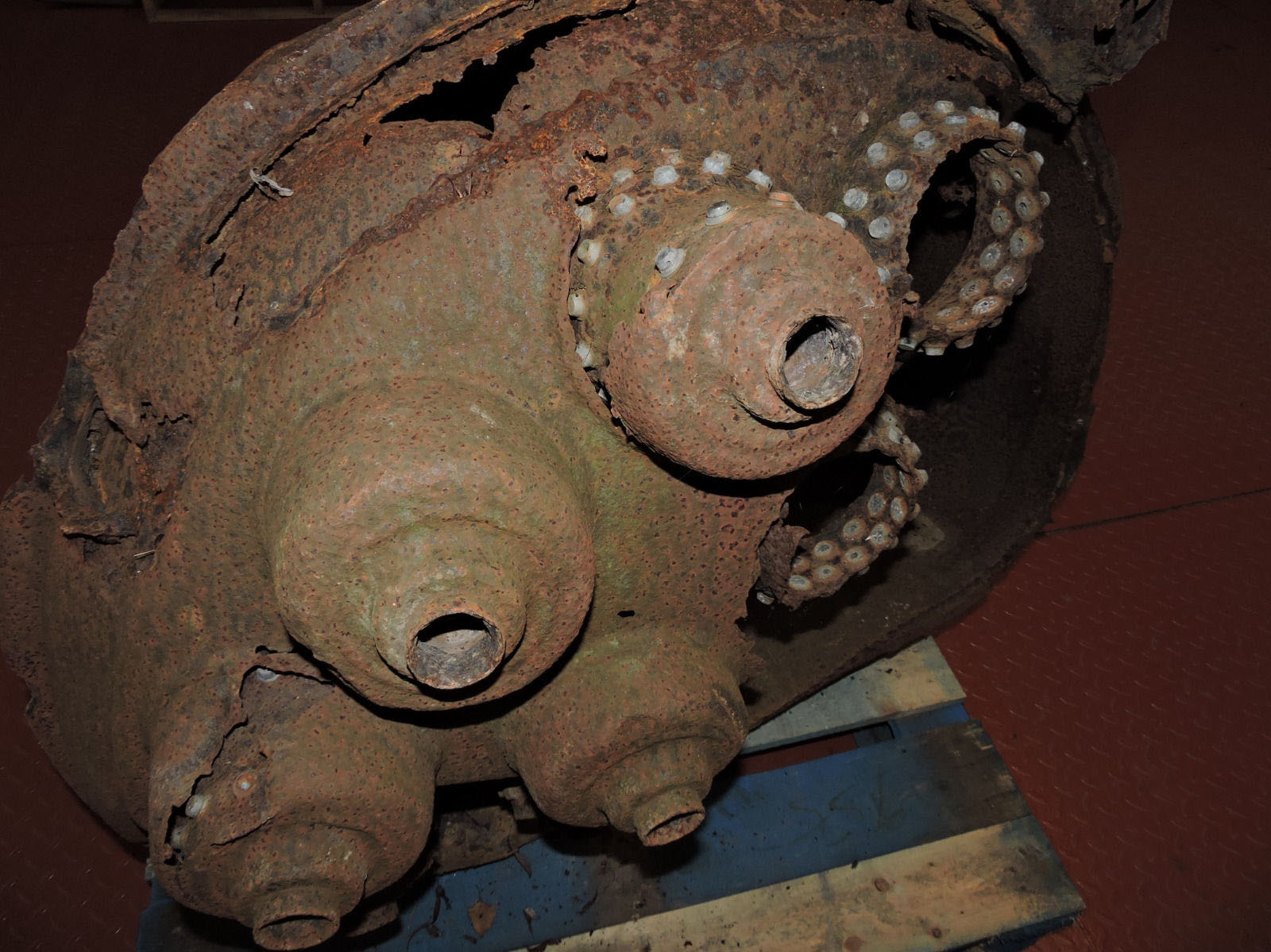
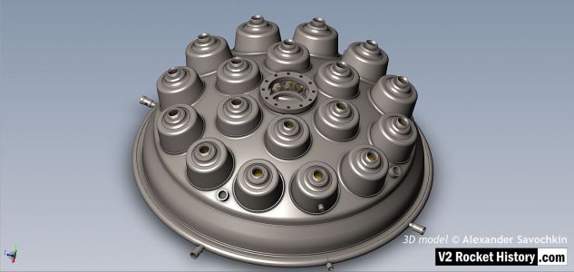
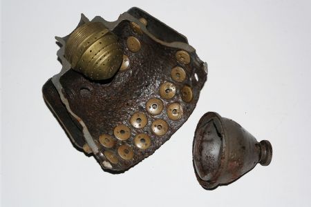
Relic of prototype A4 25-ton 1940/41 aluminium injector head basket (or pre-chamber) showing 68 copper alloy inserts in 5 rows. The standard configuration would later become 44 inserts in 3 rows 25 2mm diameter drilled holes in two rows situated at row 3 and 4 (counting from nearest the camera). Photo courtesy Host Beck Collection
| Album | V2 rocket fuel injector inserts |
| Categories | Anatomy of the V2, Combustion |

1000 kg 4B engine 1940
1000 kg 4B engine 1940
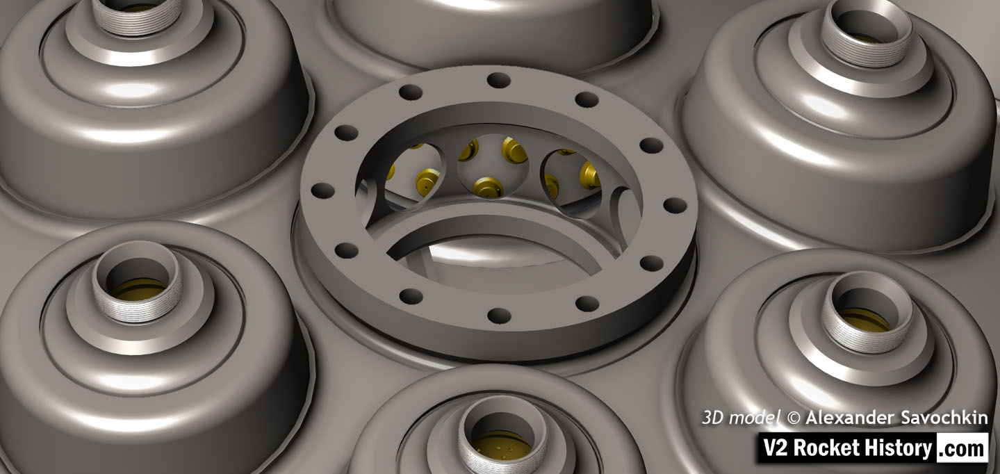
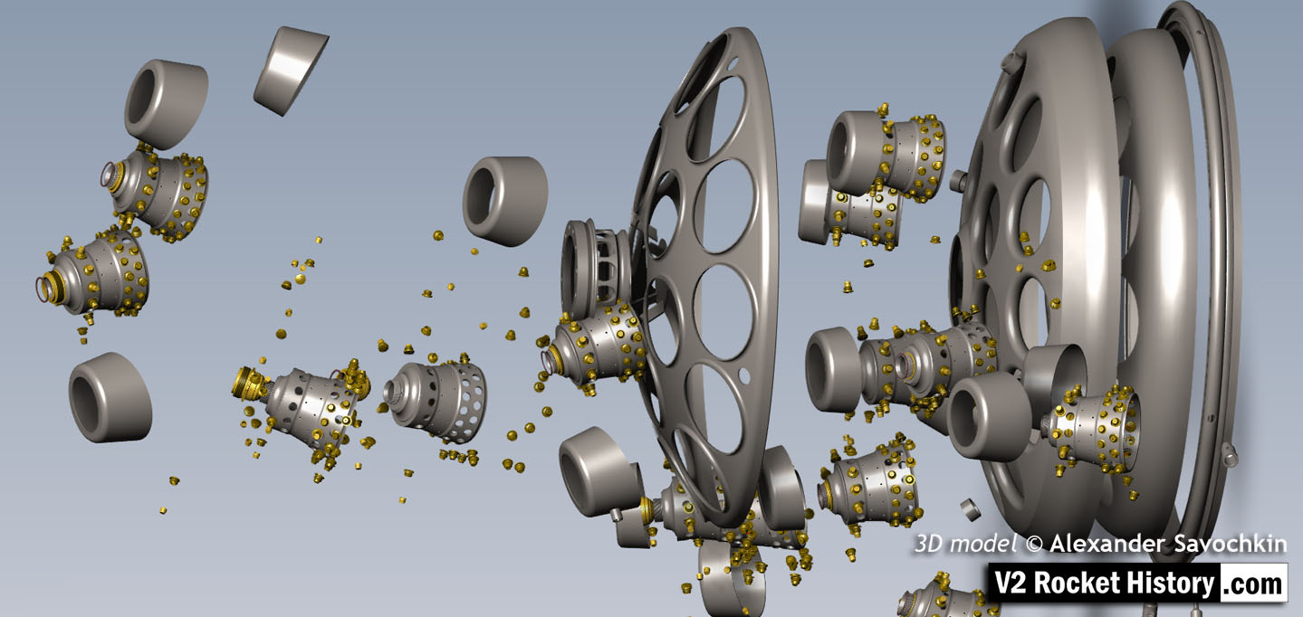
The injector head section of the 4B 1000kg thrust rocket engine is a precursor to the injector pot or ‘pre-chamber’ design used later for each of the 18-pots of the 25-ton V2 rocket engine. Most of the essential ingredients are shown in this drawing from 1940. Drawing no 1848E Deutsches Museum München online archive ref FA 014/12829

HVP Drawing of diffuser system 1939
HVP Drawing of diffuser system 1939
HVP drawing no 1203D showing burner cup ‘diffuser system’ disposition for 19-pot head (at this stage the 25 ton thrust injector head had nineteen so called ‘pre-chambers’ or pots as no central fuel valve was present). HVP drawing dated 1939.

Fuel injector specifications for 25 Ton 18-pot engine
Fuel injector specifications for 25 Ton 18-pot engine
Specification for fuel injector inserts showing orifice size, type, and A to E echelon position. Peenemünde document dated 30th October 1943. Of note on this document is the combination of high and low volume injector inserts (3304D and 3305D) in the echelon E position of the 12 cups comprising outer ring I. It shows that each cup or pot on this outer ring had 16 inserts at the lowermost position E with 12 of the inserts with three inlet apertures (3305D) and 6 with only two inlet apertures (3304D being lower flow volume) positioned in the segment covering 165 degrees and closest to the outside edge of the head. HAP11 (Heimat-Artillerie-Park 11, AKA armament code: mpe), drawing number 4554D, Deutsches Museum München

Drawing of fuel nozzle Insert 1113E 1939
Drawing of fuel nozzle Insert 1113E 1939
Drawing from the Army Experimental Station Peenemünde dated 1939. The specification describes an insert template that could be used for a range of outlet and inlet orifice sizes. The German text beginning (eingedrehte …) translates as ‘Center-line of screw used for holes to be drilled later’, and the hole dimensions are not specified on this document. HVP drawing number 1113 E, Deutsches Museum München

V2 Rocket standard screw-fit fuel Injector Insert 3304D 1944
V2 Rocket standard screw-fit fuel Injector Insert 3304D 1944
HAP11 drawing of standard 3304D fuel injector screw insert. showing details of primary swirl cavity and orrifice and all additional apertures including the four small cooling pores. HAP11 (Heimat-Artillerie-Park 11, AKA armament code: mpe), drawing number 4554D, Deutsches Museum München

Standard V2 Rocket fuel Injector Inserts
Standard V2 Rocket fuel Injector Inserts
Diagram showing cut-away presentations of the settled configuration of standard four ‘swirl’ inserts used in the V2 rocket engine’s 18-pot head from 1943 until the end of the war. The inserts are shown with their drawing code identification. All of the insert types used in the injector head are shown, however there were additional screw-in type fuel supply inserts, used to provide a fuel cooling balance function, located radially in the lower part of the combustion cavity.

2131E Inserts in burner cup Peenemünde workshop relic
2131E Inserts in burner cup Peenemünde workshop relic
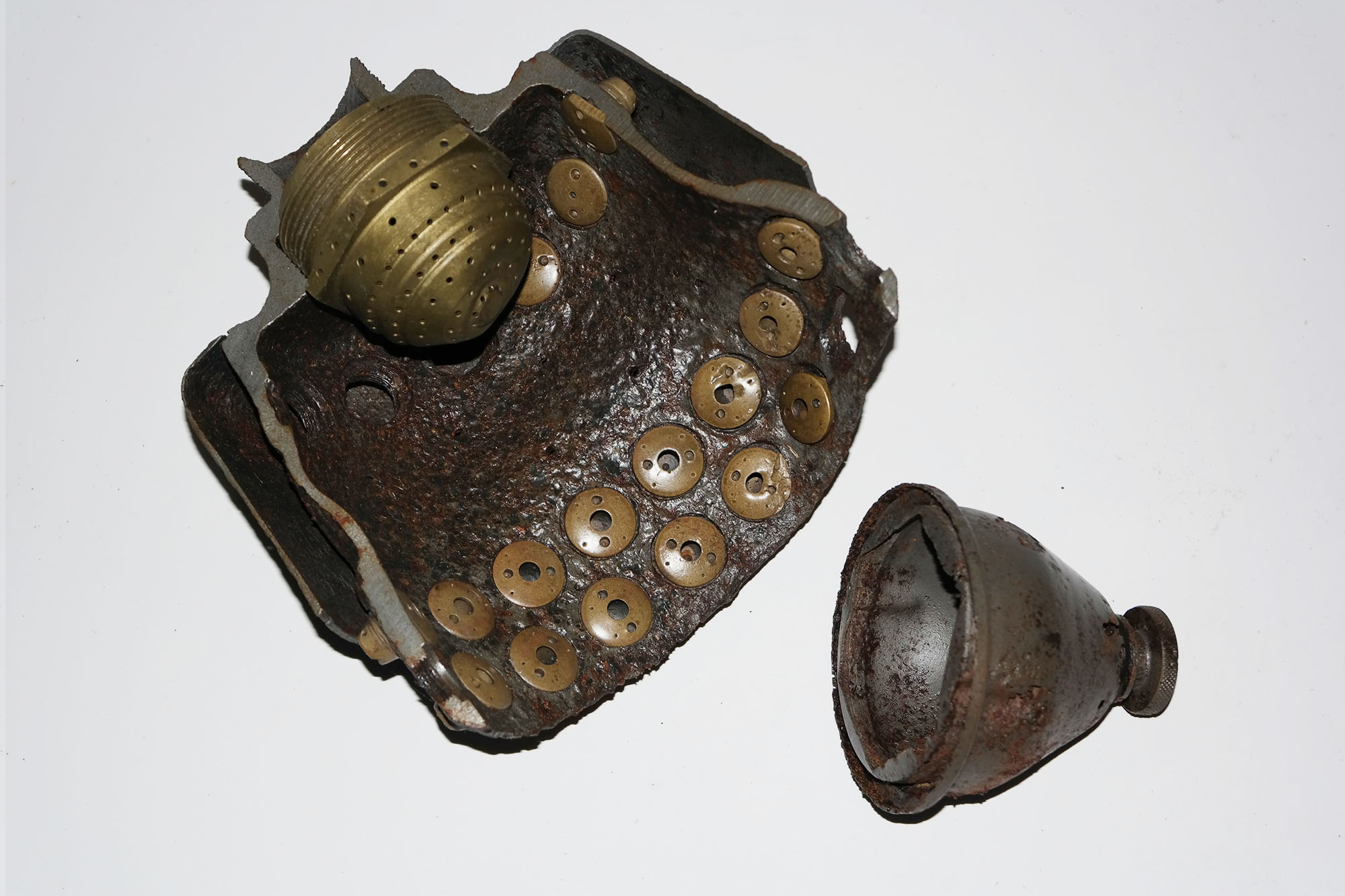
Photo shows a small section of the burner cup with row A (2131E) fuel injector inserts with three row B drilled holes below. The two undamaged inserts carry the armament code ‘csl’. The relic was found near a workshop in the Development works Pennemünde. Slag from the cutting flame and damage to the inserts at both ends of the relic would indicate that the section was cut from a steel burner cup using a gas cutter (fuel and oxygen) for purposes unknown. V2RH collection image

V2 fuel injector Insert test rig
V2 fuel injector Insert test rig
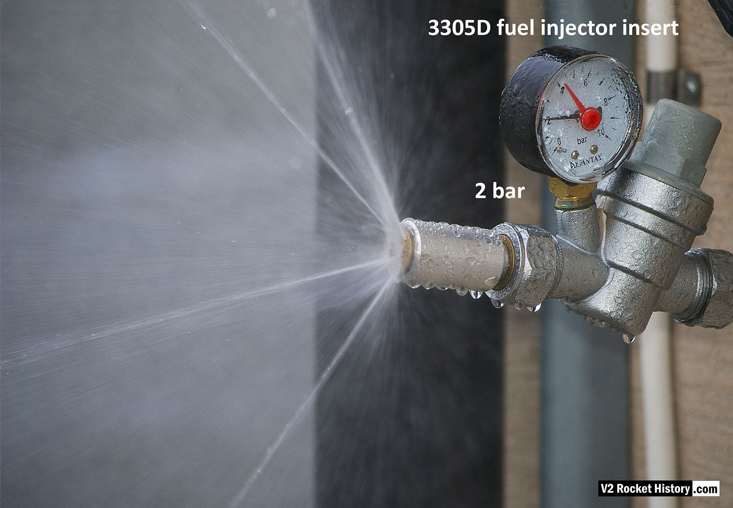
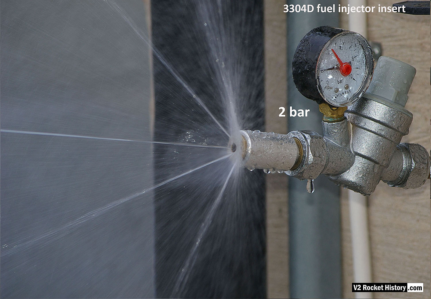
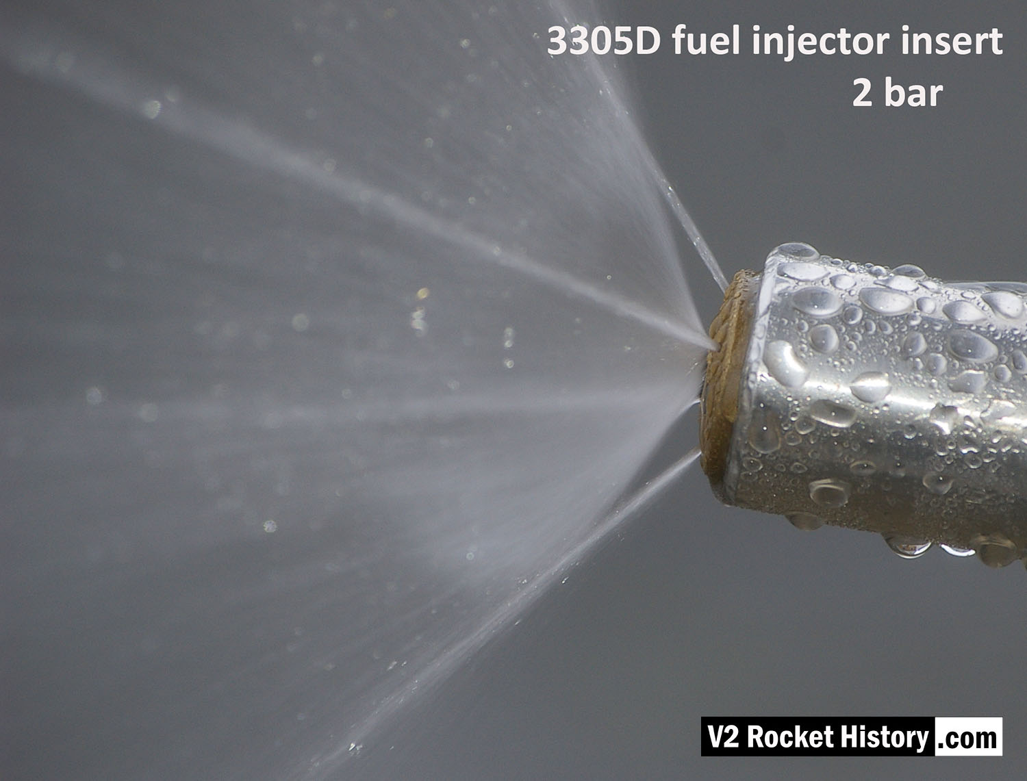
Single nozzle insert test rig used by V2 Rocket History to test spray shape and volume at supply pressures consistent with fuel pressures specified for the injector head of summer 1944. The test system features an adjustable pressure regulator and fluid pressure gauge. For test purposes the device was simply connected to a relatively high pressure mains water supply. And although water does not have the same viscosity of the 75% Ethenol to 25% water mix of the V2’s fuel it was considered close enough by the German technicians, who regularly used plain water as a substitute when testing issues related to furl flow rather than combustion. A 2131E fuel injector insert is shown installed in the holder at the front of the rig, but as the thread was the same on all inserts the nozzle can be changed for other models easily with aid of a pin spanner. See video for a demonstration of this simple test system.

Test Rig With E Type Insert
Test Rig With E Type Insert
Single nozzle insert test rig used by V2 Rocket History to test spray shape and volume at fluid supply pressures consistent with fuel pressures specified for the injector head of summer 1944. A 2131E fuel injector insert is installed in the holder at the front of the test rig, but as the thread was the same on all inserts the nozzle can be changed for other models easily with aid of a pin spanner. See video for a demonstration of this simple test system.

Swirl nozzle insert set 2
Swirl nozzle insert set 2
Fuel injector inserts for production series 18-pot injector head showing general shape and thread position. For further details see associated image. The lowermost insert have been halved to reveal the cavity shape, orifice edge, inlet and cooling apertures. V2RH image

Industrial magazine advert for Gustav Schlick 1918
Industrial magazine advert for Gustav Schlick 1918
Industrial magazine advert for Gustav Schlick printed in 1918 and showing graphic of steam boiler jets. The company, formed in 1902, had a wide expertise in all aspects of industrial spray technology and were able to steer the direction of fuel injector development along fruitful lines after they became consulting contractors to Dr Walter Thiel’s combustion research group in 1937.
Missile guidance equipment
Images of guidance and missile control equiment


Description
Relic of prototype A4 25-ton 1940/41 aluminium injector head basket (or pre-chamber) showing 68 copper alloy inserts in 5 rows. The standard configuration would later become 44 inserts in 3 rows 25 2mm diameter drilled holes in two rows situated at row 3 and 4 (counting from nearest the camera). Photo courtesy Host Beck Collection
Location
