

Archives: Gmedia Albums


The Enigmas
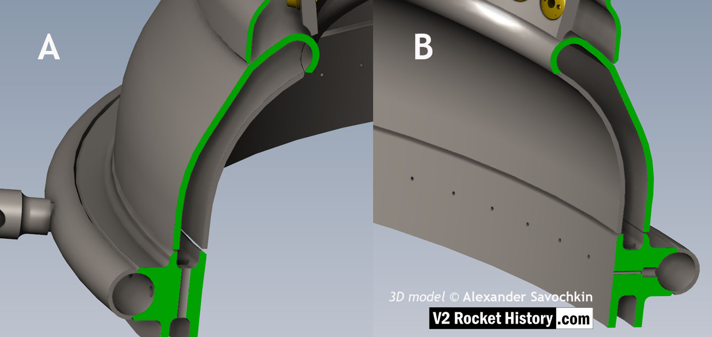
18-pot Upper Veil Manifold detail
18-pot Upper Veil Manifold detail
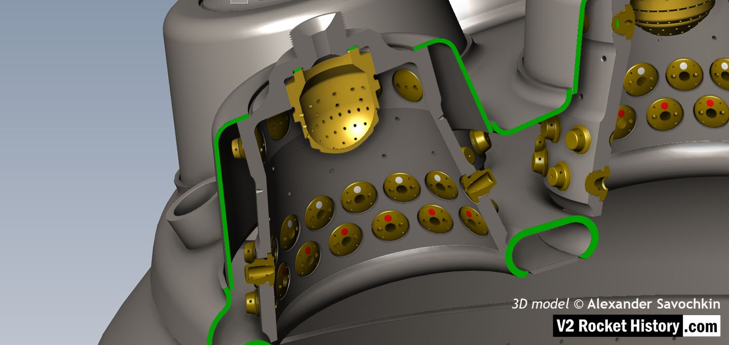
Close-up detail showing independent pathway for fuel passing into injector head and fuel passed down from the head to be used for veil cooling system. Fig. A shows vertical passages for overall fuel feed to the head and Fig.B shows horizontal pathway for veil coolant fed from the head via the veil coolant distributor ring or manifold. 3D model by Alexander Savochkin
V2 rocket 18-pot Head: Top
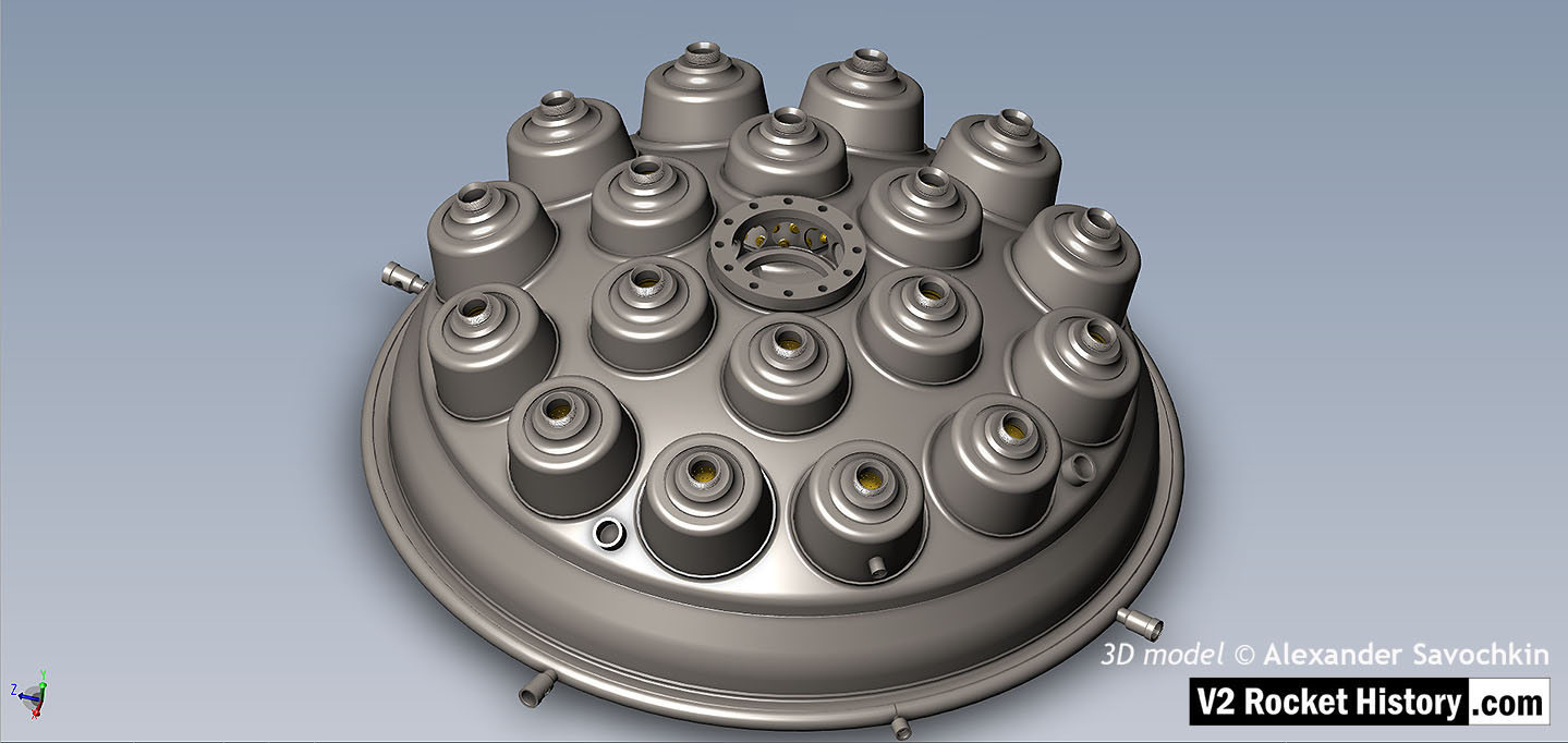
V2 rocket 18-pot Head: Top
View of injector head showing 18 liquid propellant (LOX and fuel) diffuser cups and head fuel valve seating ring at centre, (see other images for insert and position nomenclature). Visible immediately below the valve seat are the large connecting holes that allow fuel to flow from the inlet manifold and cooling jacket to the injector space (some brass injector inserts can be seen through the holes) after the head fuel valve is released to be opened by the turbo-pump supply pressure. The four veil cooling inlet connectors are well shown as are two of the outlet connection holes immediately above them. 3D model by Alexander Savochkin
18-pot Head Fuel Valve Seat close-up
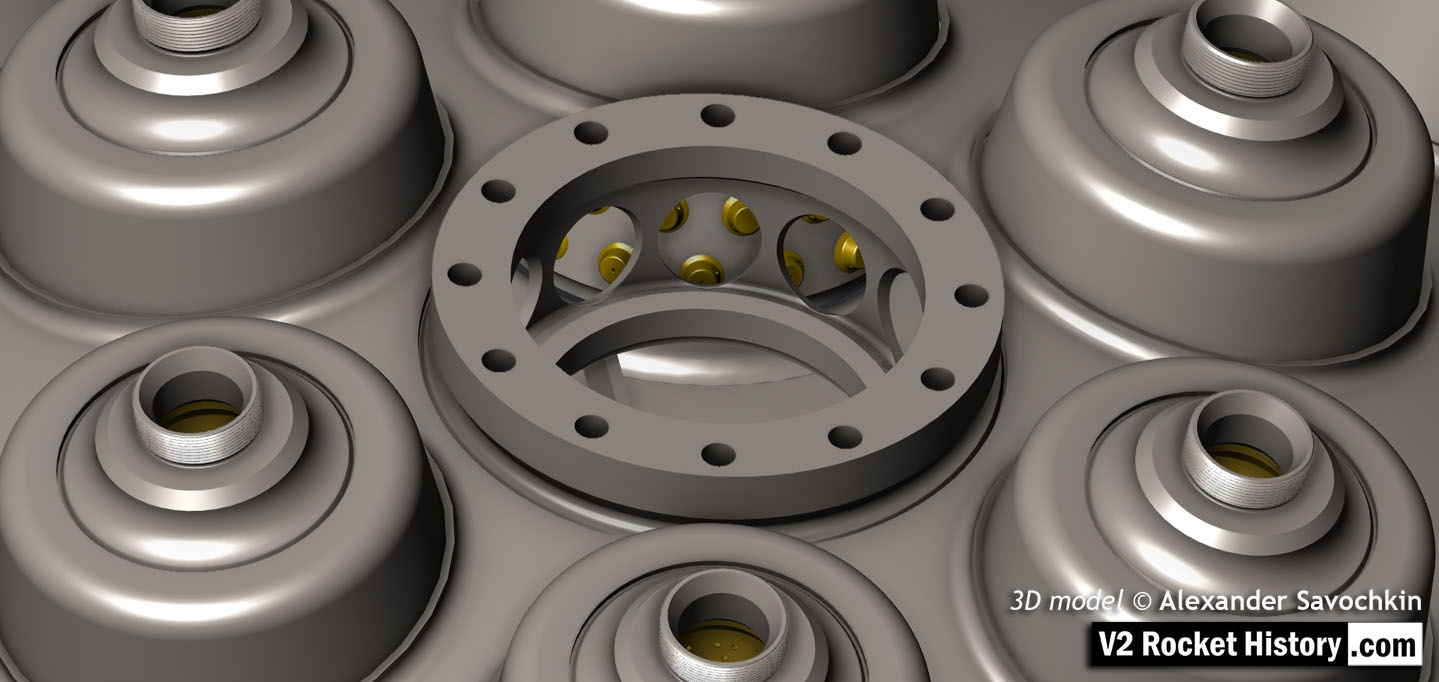
18-pot Head Fuel Valve Seat close-up
A close-up view of the head fuel valve mounting flange (showing 12 fastener holes). Visible immediately below the top flange are the large connecting holes that allow fuel to flow from the inlet manifold and cooling jacket to the injector space (some brass injector inserts can be seen through the holes) after the head fuel valve is released to be opened by the turbo-pump supply pressure.
18-pot head: Cutaway 2
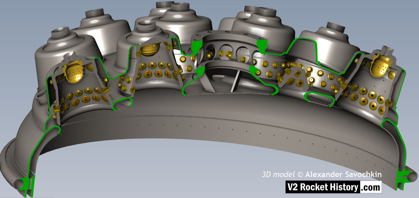
18-pot head: Cutaway 2
Here the 18-pot head model has been cutaway to show the fuel cooling and fuel delivery spaces. the cooling jacket layer can be seen in the lowermost area of the head – below the centrally positioned fuel valve seat, between each cup at the lowest point, and ruining down toward the first set of veil cooling pores and the topmost coolant distributor ring. Note that the veil cooling system does not communicate with the regenerative cooling jacket and has its own feed pipes drawing fuel from the head injector space and not the cooling space. Visible immediately above the valve seat are the large connecting holes that allow fuel to flow from the inlet manifold and cooling jacket to the injector space after the head fuel valve is released to be opened by the turbo-pump supply pressure. 3D model by Alexander Savochkin
18-pot Cutaway 1
18-pot Cutaway 1
Liquid propellent (LOX and fuel) diffuser cup, showing three rings or echelons (A,D,& E) of brass injector inserts as well as two rows of drilled fuel feed holes. The LOX spray head is shown in the centre. Note the simple ‘shower head or watering can’ design of the LOX diffuser. A sealing washer can be seen fitted between the LOX diffuser and the steel cup. 3D model by Alexander Savochkin
F1: Fertigungshalle Eins

Industrial magazine advert for Gustav Schlick 1918
Industrial magazine advert for Gustav Schlick 1918
Industrial magazine advert for Gustav Schlick printed in 1918 and showing graphic of steam boiler jets. The company, formed in 1902, had a wide expertise in all aspects of industrial spray technology and were able to steer the direction of fuel injector development along fruitful lines after they became consulting contractors to Dr Walter Thiel’s combustion research group in 1937.

Sample set 3303D inserts
Sample set 3303D inserts
Sample set of 3303D type fuel injector inserts that were found in Peenemünde in part of a group that were bunched together in a space about 300mm in diameter with the remains of packaging. They appear to be manufacturing samples and and some have been graded with numbers 1,2,3, as well as with red and white paint to show the burner cup echelon position (C or D). Five different manufacturers are represented in this group. V2RH collection image
KSB’s ebb armament code on V2 turbo-pump
KSB’s ebb armament code on V2 turbo-pump
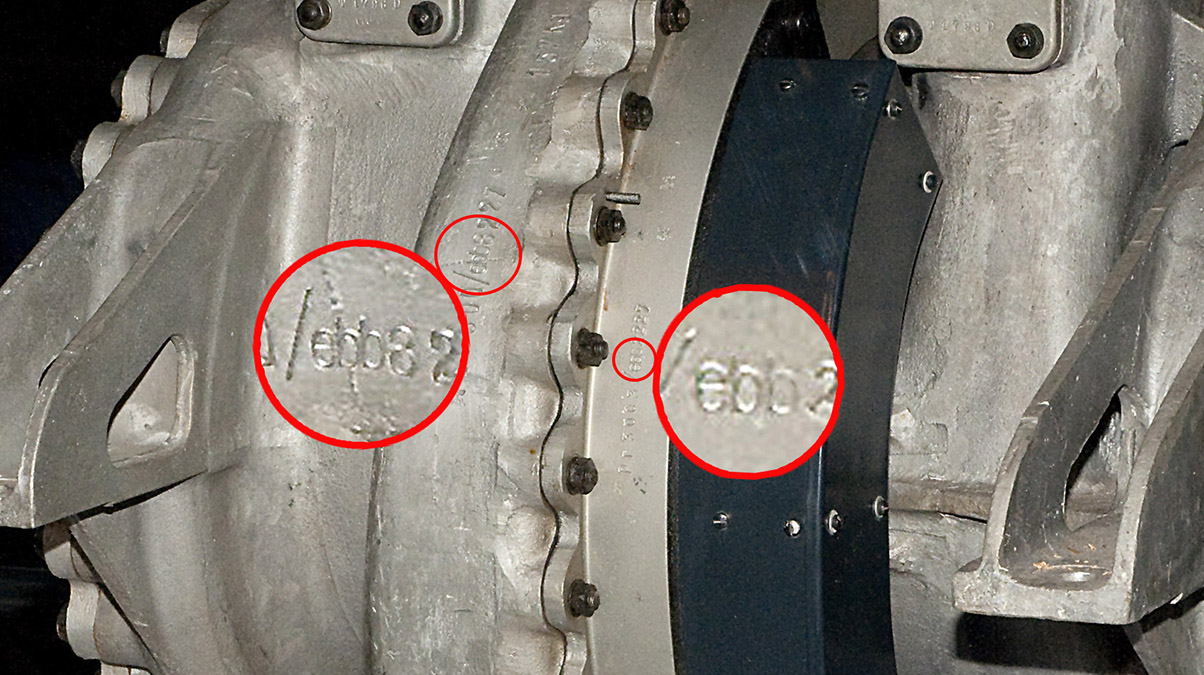
A complete V2 rocket turbo-pump on public display in the USA at the Smithsonian National Air and Space Museum in Washington DC showing Klein Schanzlin & Becker’s wartime contractor armament code – ebb. Smithsonian National Air and Space Museum exhibit.
Klein Schanzlin & Becker and KS Oddesse’s secret contractor codes
Klein Schanzlin & Becker and KS Oddesse’s secret contractor codes
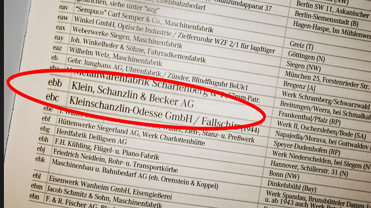
Page from the book, German Secret Armament Codes until 1945 by Michael Heidle (Visier Edition 2016) showing Klein Schanzlin & Becker’s wartime contractor armament code – ebb and Klein Schanzlin Odesse as ebc. ISBN: 978-3-944196-18-3
| Album | Turbopump parts and relics |
| Category | Turbo-pump |
Askania rudder servo ‘Rudermaschine LRM 3’
Askania rudder servo ‘Rudermaschine LRM 3’
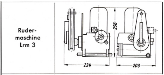
A schematic drawing of the Askania rudder servo ‘Rudermaschine LRM 3’showing the critical compact dimentions of the device making it ideal for retro fit projects for smaller aircraft.
Preschona trade advert
Preschona trade advert
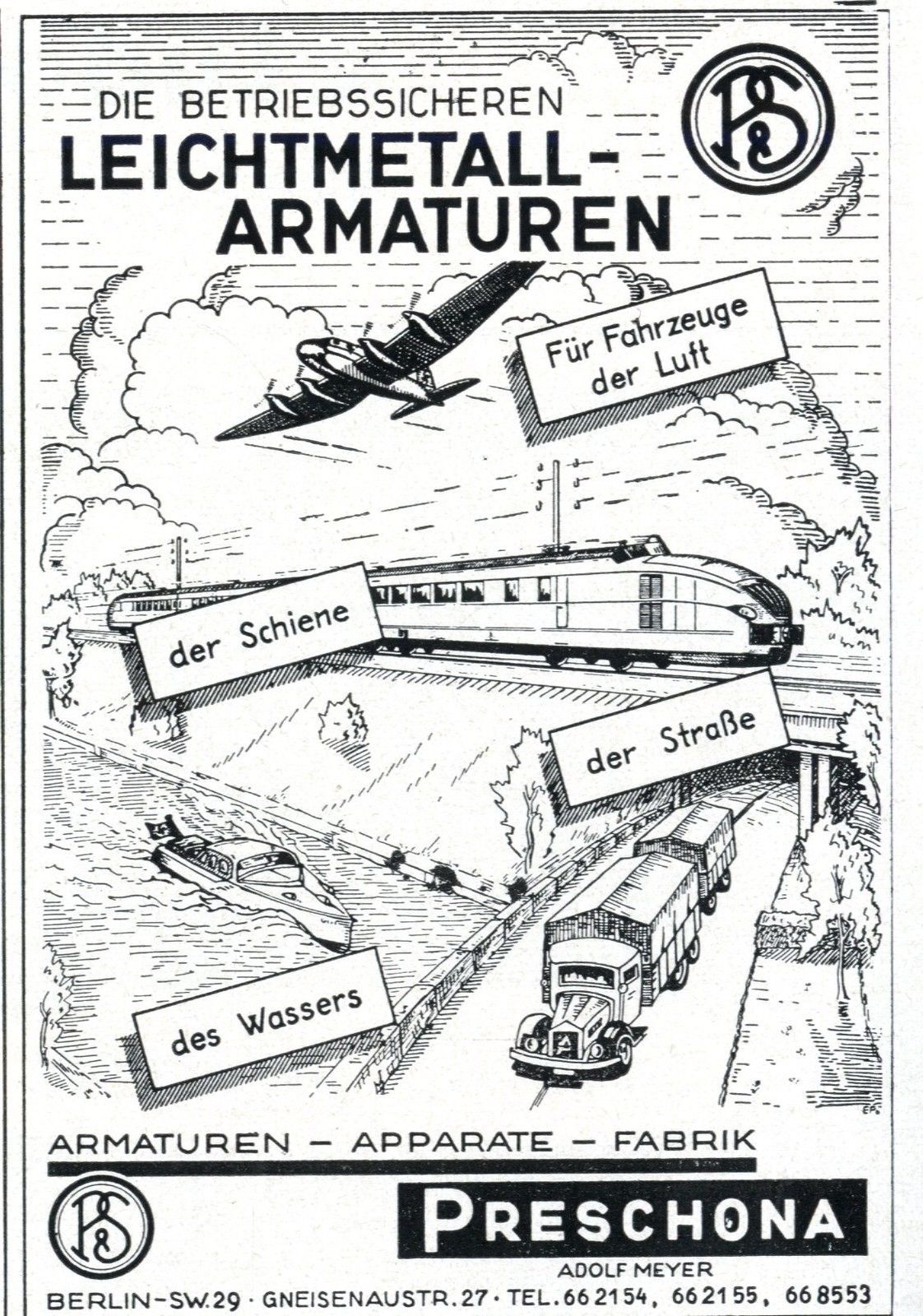
Trade literature advert for the Preschona company (Adolf Meyer) in Berlin, Germany. The company was a supply contractor and (among other items) manufactured the non-return valve for the steam turbine exhaust heat exchanger, employed to volatilise a small portion of liquid oxygen (LOX) to pressurise the LOX tank to maintain critical flow volume to the LOX turbo-pump.
Equipment bays
V2 missile on rail wagon showing control bays
V2 missile on rail wagon showing control bays
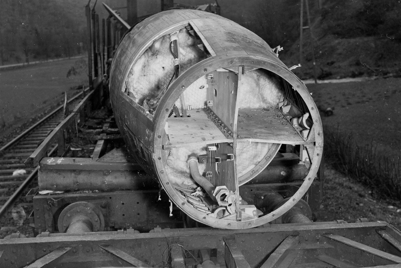
Incomplete V2 missile on rail transporter. All 4 control compartments are well shown. The fuel tank connection pipe can be seen but not much else. All of the control equipment has been removed. Plainly visible is the chicken wire holding the fiber wool tank insulation in place. Today this would be called ‘Galvanised hexagonal network restraining matrix, and be supplied by a blue chip Aerospace company for $800 per square inch. In the 1940s, it was just chicken wire at a 2 dollars for a 100 ft roll.
| Album | Equipment bays |
Control compartments 1 & 4
Control compartments 1 & 4
Control compartments 1 (upper) & 4 (lower) Image copyright Imperial War Museum
| Album | Equipment bays |
| Category | Missile guidence |
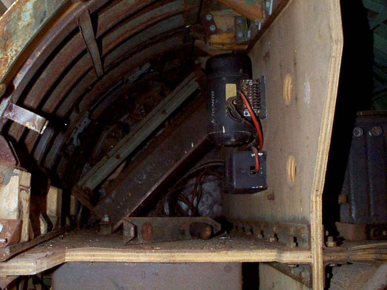
Control compartment 3
Control compartment 3
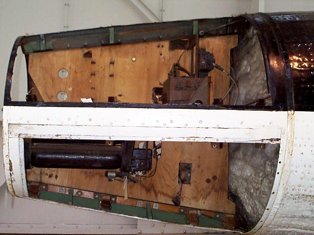
Control compartments 3 showing gyro mounting platform with two gyros and DC motor driven 3 phase AC voltage generator. The alcohol tank pressurisation pipe is also shown running through the equipment bay (large silver coloured pipe). Image copyright Imperial War Museum
| Album | Equipment bays |
| Category | Guidence |
Control compartment 1
Control compartment 1
Control compartments 1. Image copyright Imperial War Museum
| Album | Equipment bays |
| Category | Electrical connection |
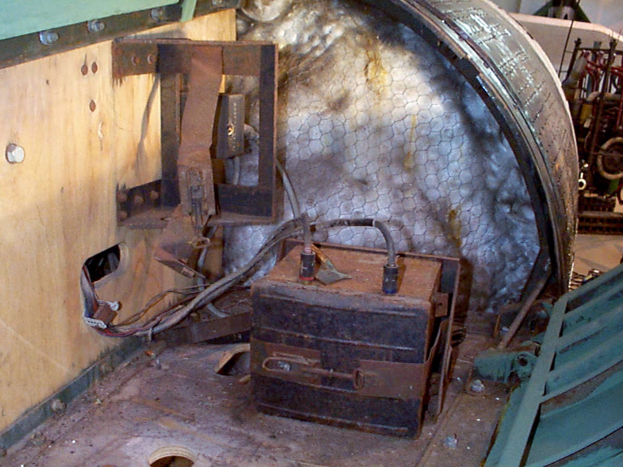
Control compartment 2
Control compartment 2
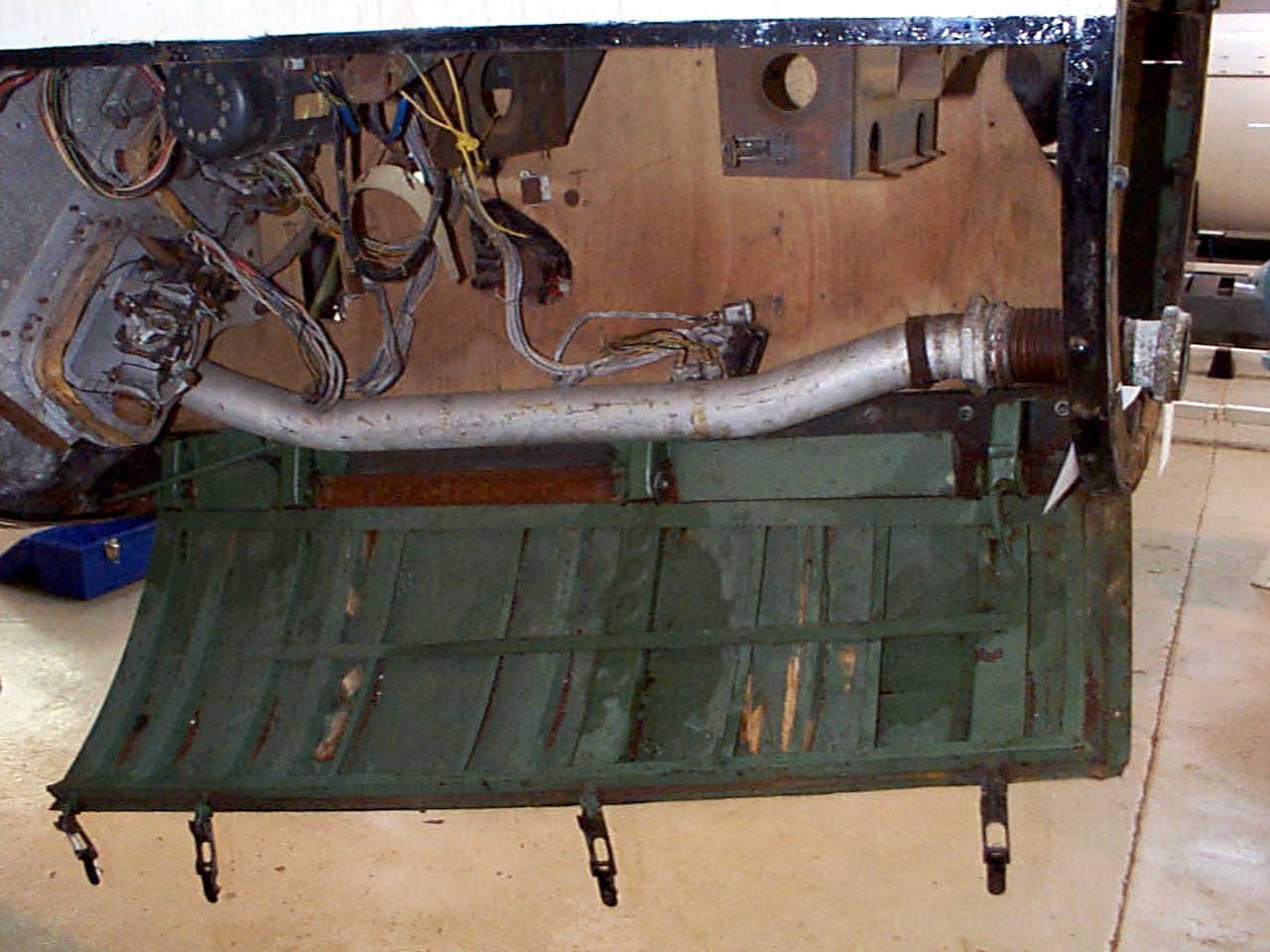
Control compartment 2 showing plywood separation panels, Oemig umformer (DC to 3 phase AC voltage generator), and voltage frequency control box. Towards the rear the ground connection plugs can just be seen and the mechanism of the cable release trap door (see cat flap!). Image copyright Imperial War Museum
| Album | Equipment bays |
| Category | Electrical connection |
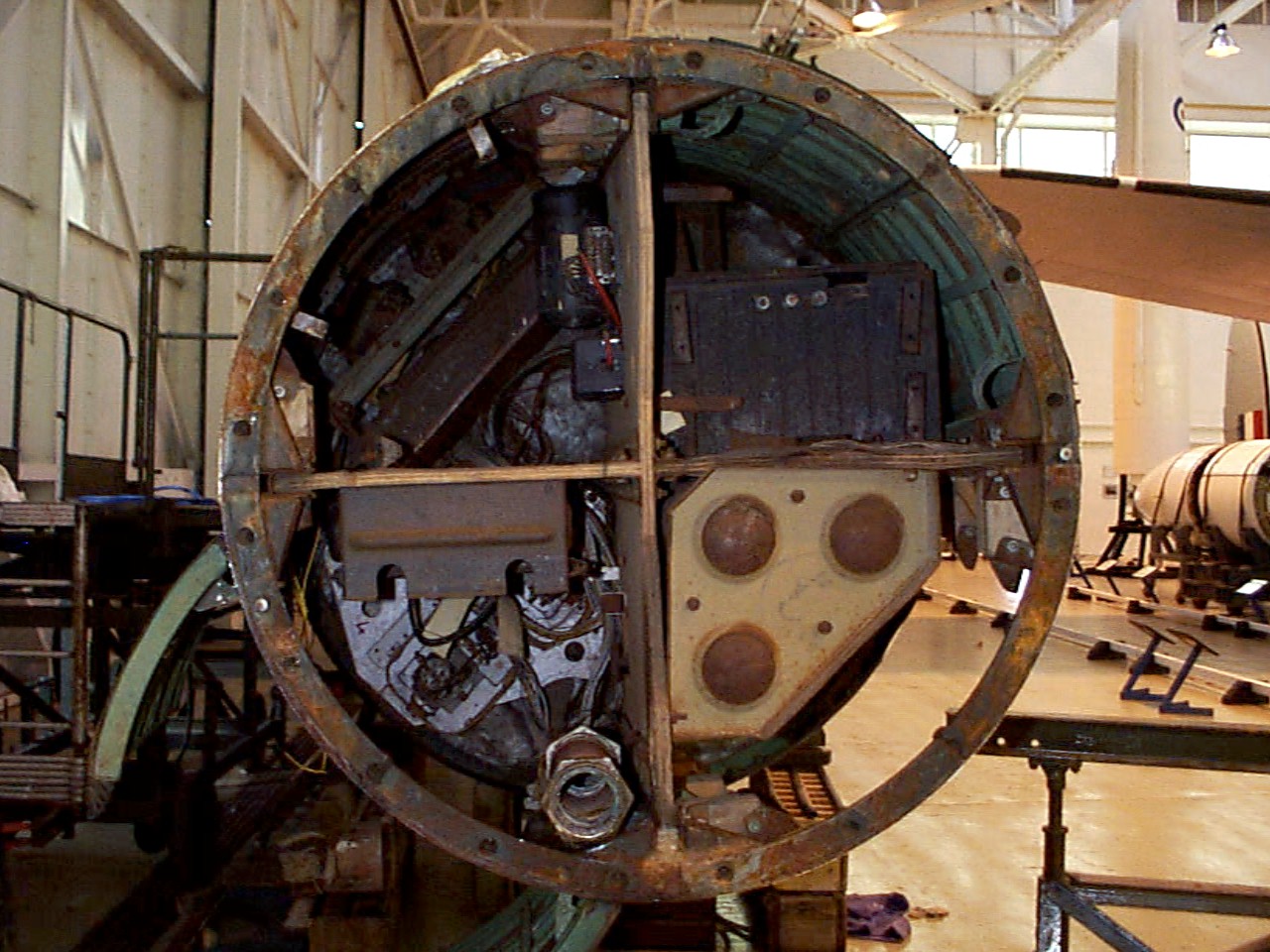
Control compartments – all 4 top view
Control compartments – all 4 top view
Control compartment 1 top right, 2 top left, 3 bottom left, and 4 bottom right. The fuel tank pressurisation pipe upper connection point is well shown at about 6 o’clock (compartment 3) and just above and to the right the upper plate of the air (N) tank rack (tan colour). Image copyright Imperial War Museum
showing plywood separation panels, Oemig umform
| Album | Equipment bays |
Missile guidance equipment
Images of guidance and missile control equiment


Missile guidance equipment
Images of guidance and missile control equiment
LEV-3 Horizont and Vertikant gyroscope system 1940
category:Missile guidence, Sub-assemblies


Description
LEV-3 V2 missile gyroscope system with mounting plate. The third component of this system, the Muller gyroscopic accelerometer, is missing – the 2x mounting points can be seen on the right-hand side of the mounting plate.
Location
