

Archives: Gmedia Albums


The Enigmas

LEV-3 Horizont and Vertikant gyroscope system 1940
LEV-3 Horizont and Vertikant gyroscope system 1940
LEV-3 V2 missile gyroscope system with mounting plate. The third component of this system, the Muller gyroscopic accelerometer, is missing – the 2x mounting points can be seen on the right-hand side of the mounting plate.
| Album | Missile guidance equipment |
| Categories | Missile guidence, Sub-assemblies |
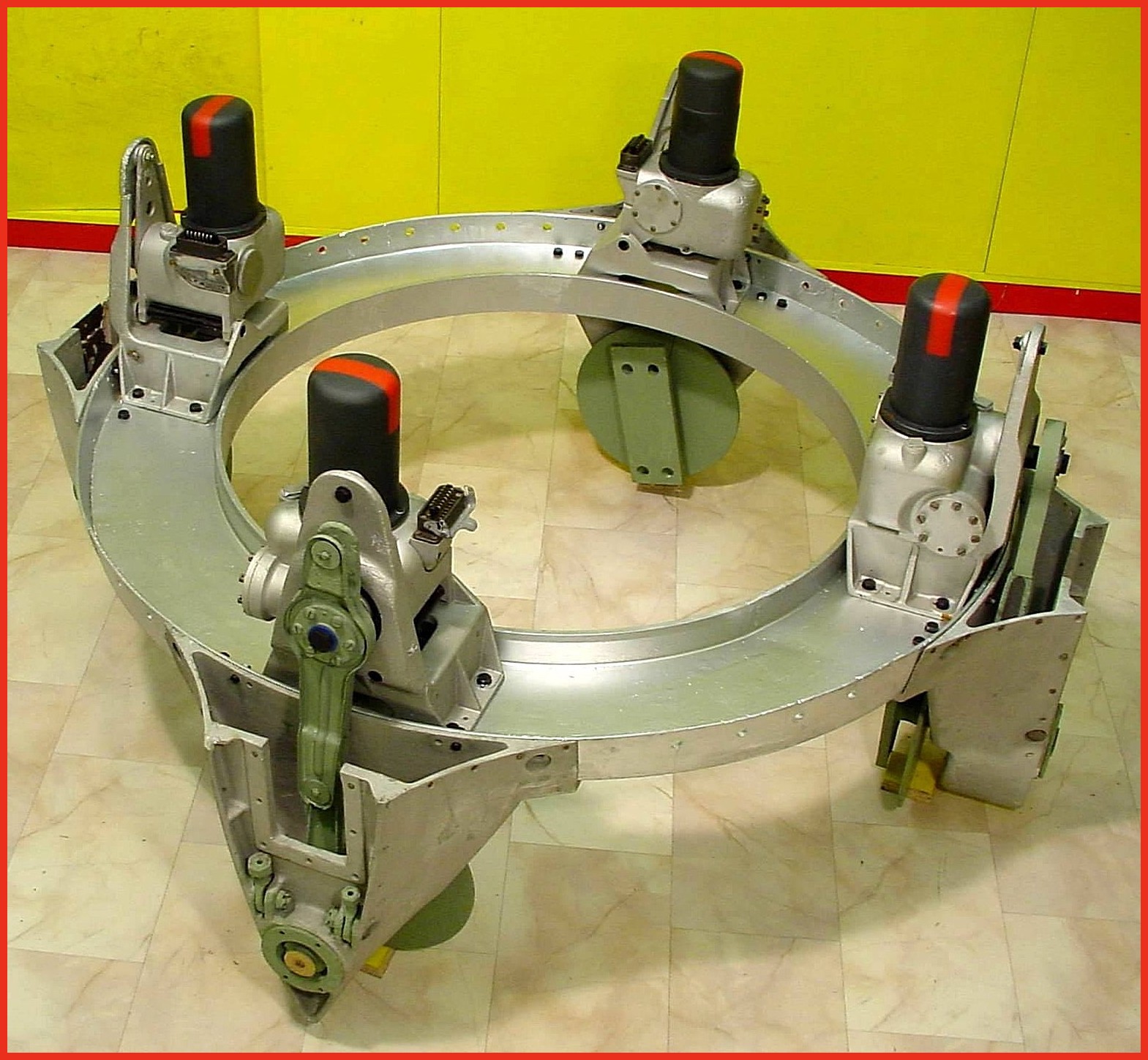
A4-V2 thrust ring with control servos (Abtriebsring) ©THBC
A4-V2 thrust ring with control servos (Abtriebsring) ©THBC
Photo shows cast aluminium thrust ring with electro-hydraulic servos in position. Note different crank lever shapes (pale green arm on servo) for fins 1/3 and 2/4 This excellent restoration is the work of Horst Beck. Photo copyright: The Horst Beck Collection
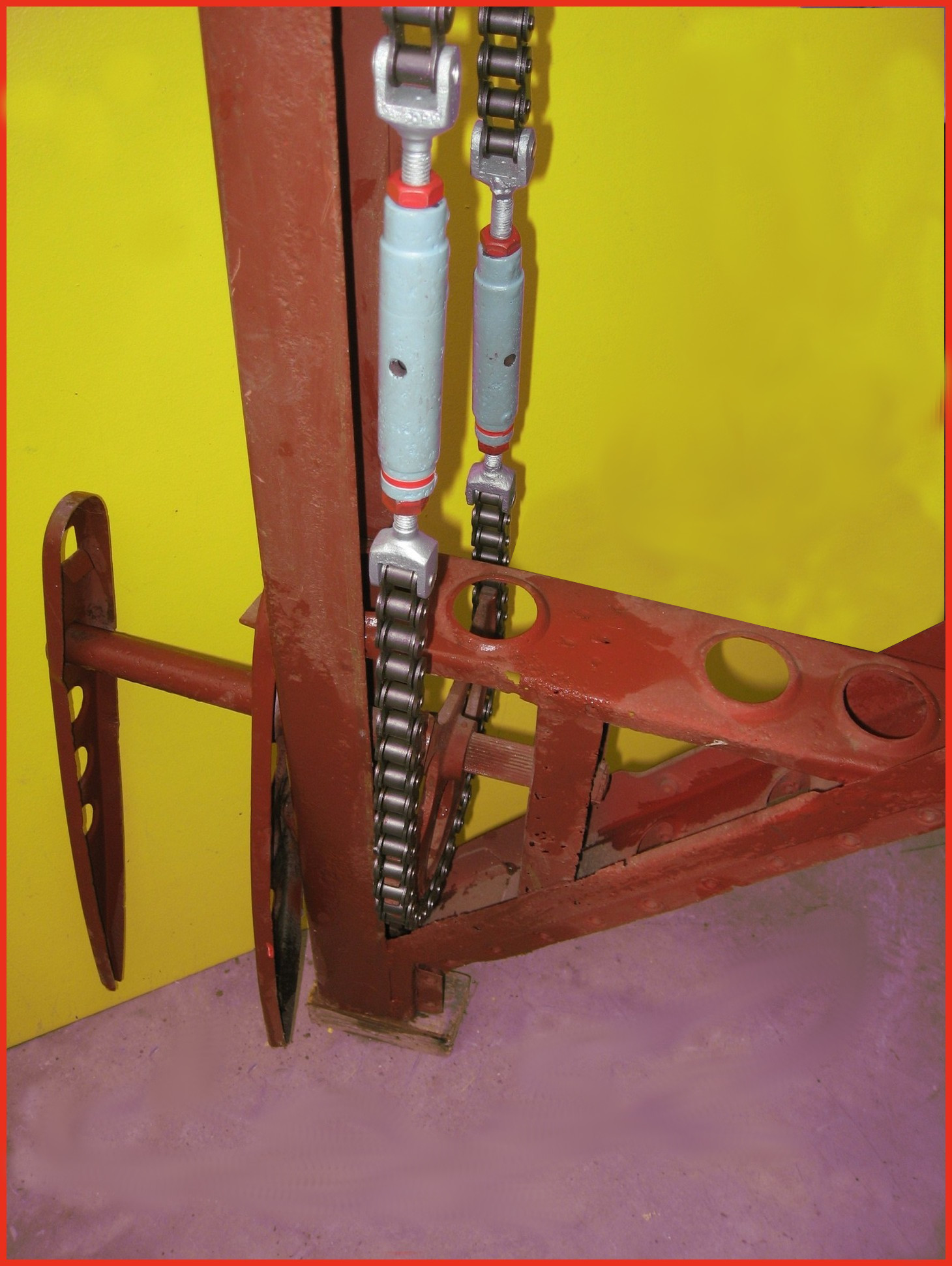
A4-V2 air rudder detail. ©THBC
A4-V2 air rudder detail. ©THBC
Photo shows restored air-rudder and fin detail. The grey painted barrel-strainers are both adjusted independently to reduce slack in the drive chain and avoid introducing a deflection bias in the air rudder. The 1.9kg counterbalance weight normally located at the top of the trim fin (or air rudder) is missing in this presentation. This excellent restoration is the work of Horst Beck. Photo copyright: The Horst Beck Collection

Restored graphite vane thrust ring support housings. ©THBC
Restored graphite vane thrust ring support housings. ©THBC
Photo shows four restored graphite jet vane support blocks and bearing housings. The round plates we can see here act as heat sinks and allow heat to radiate away from the support block and bearing to help prevent expansion due to relatively rapid and uneven temperature distribution accumulation. The graphite vanes were quite brittle and cracking caused by rapid and uneven expansion could cause the vane to disintegrate. The area around the graphite vanes was exposed to the accumulation of heat not merely as a result of duration of the motor burn time but temperature was also increased at higher rates as the jet plume expanded with the decreasing atmospheric pressure as the missile gained altitude. This excellent restoration is the work of Horst Beck. Photo copyright: The Horst Beck Collection
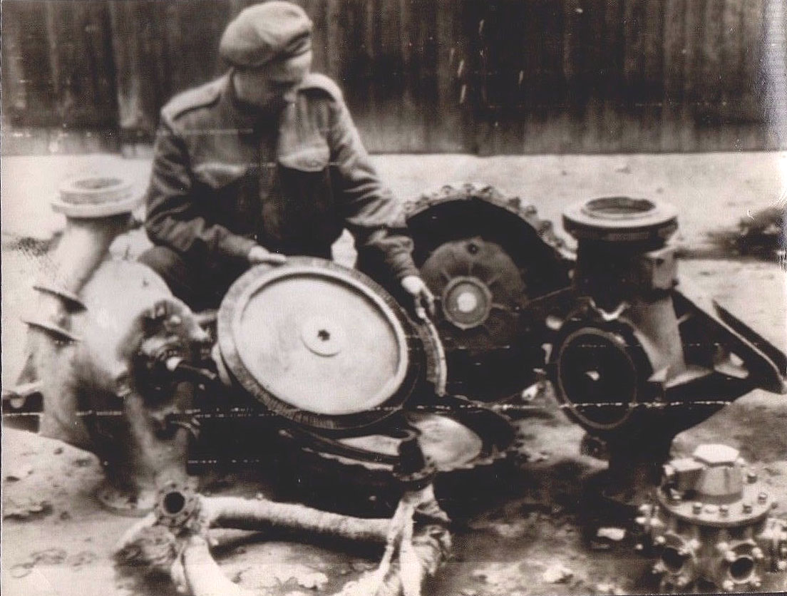
Turbo Pump Parts Showing Steam Rotor
Turbo Pump Parts Showing Steam Rotor
Image shows allied soldier examining remains of V2 rocket turbo-pump after impact. The soldier is holding the steam turbine rotor – the large size of this part is well shown in this photo. The still lagged steam inlet manifold can be seen in the left foreground and the LOX outlet manifold (and valve, topmost) can be seen in the lower right corner.
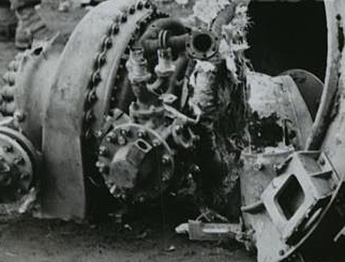
Smashed TP Antwerp Impact
Smashed TP Antwerp Impact
Picture shows tubo-pump debris from impact site. LOX manifold clearly seen (3 in 1 outlet pipes, upper center of image – the one to its right, 2 o’clock position, and left, 11 o’clock position are both broken off).The LOX flow electric control valve is also well displayed in this image (LOX valve head is slightly low and left of center, part nearest camera). The electrical connection to the LOX valve has broken away leaving its empty socket pointing upwards and to the right.
A4-V2 missile steam generator detail
A4-V2 missile steam generator detail
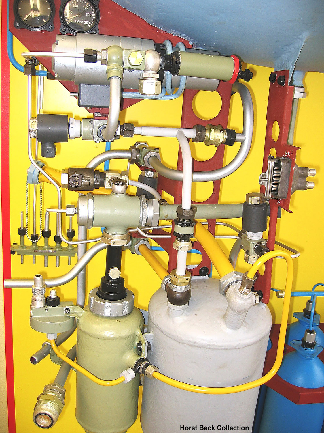
A4 missile steam generator detail. This excellent presentation was rebuilt from original refurbished parts by Horst Beck. See our video article The V2 Rocket Turbo-Pump for a technical exposition of the parts shown in this photo. Image courtesy The Horst Beck Collection
Klein Schanzlin & Becker centrifug-pump advert
Klein Schanzlin & Becker centrifug-pump advert
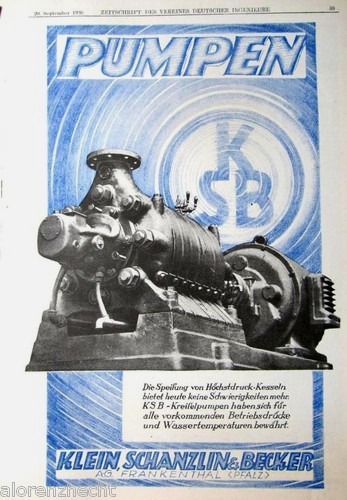
Klein Schanzlin & Becker electric centrifugal-pump advert.
Early belt powered centrifugal pump by KSB with V2 TP features
Early belt powered centrifugal pump by KSB with V2 TP features
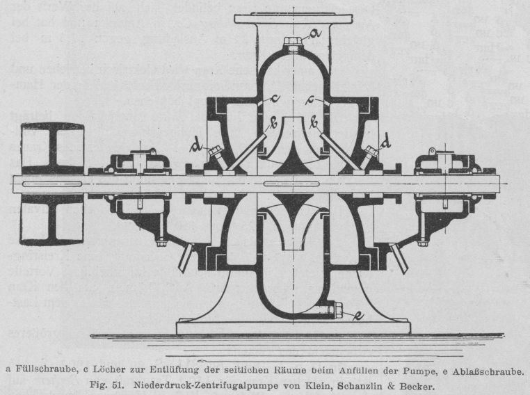
Early belt powered centrifugal pump by Klein Schanzlin & Becker. This schematic shows an early 20th century centrifugal pump designed and manufactured by KSB. The drawing appears to show auto-purge pathways at points marked C as well continuous lubrication pathways at B. Both of these important ideas would later feature in the propellant pump of the A4-V2 missile.
1930s Trade advert for Klein Schanzlin & Becker
1930s Trade advert for Klein Schanzlin & Becker
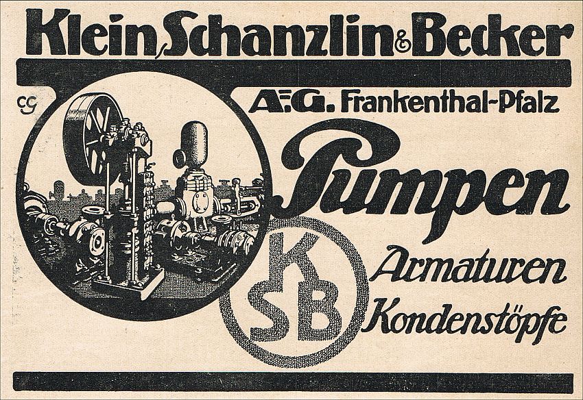
Trade advertisement for Klein Schanzlin & Becker (KSB supplier code ebb). KSB were the primary contractor for A4-V2 missile’s steam turbine driven dual propellant pump system.
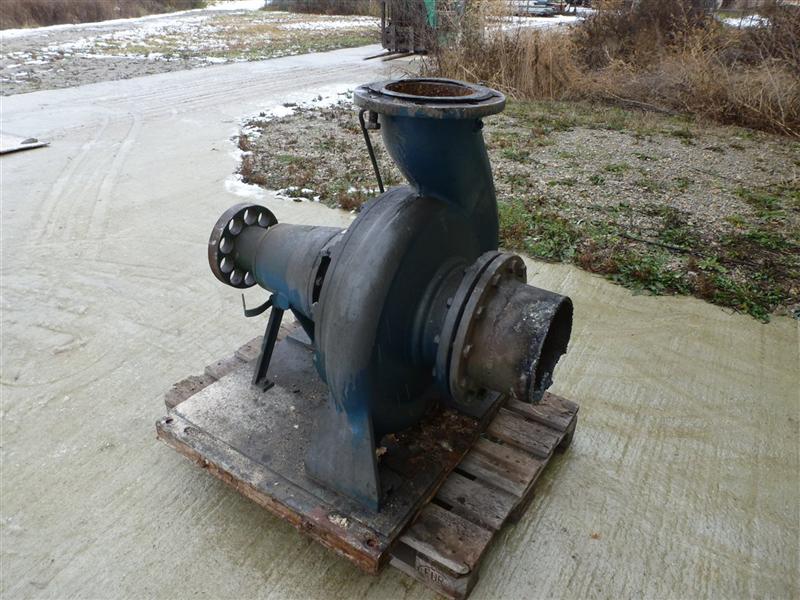
Family photo? Industrial volute case centrifugal pump by KSB
Family photo? Industrial volute case centrifugal pump by KSB
Large industrial volute case centrifugal pump by Klein Schanzlin & Becker. This image highlights the ‘genetic’similarity and family resemblance between KSB’s current and historical product range and the visible features of the A4-V2 missile Turbo-Pump (TP). Apart from the general shape of the cast spiral-volute case and its connection flanges, the ‘soft’ shaft connection (disk with holes on the extreme left of the pump) is very reminiscent of the semi-flexible shaft connection point linking one side the steam turbine rotor shaft to the shaft carrying a propellent pump rotor seen in the A4-V2 missile TP. Family photo? Industrial volute case centrifugal pump by KSB
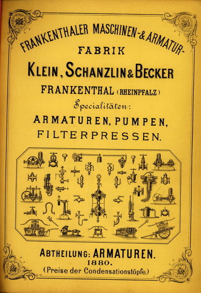
KSB catalogue from 1880
KSB catalogue from 1880
Cover of catalogue published in 1880 showing the KSB product range
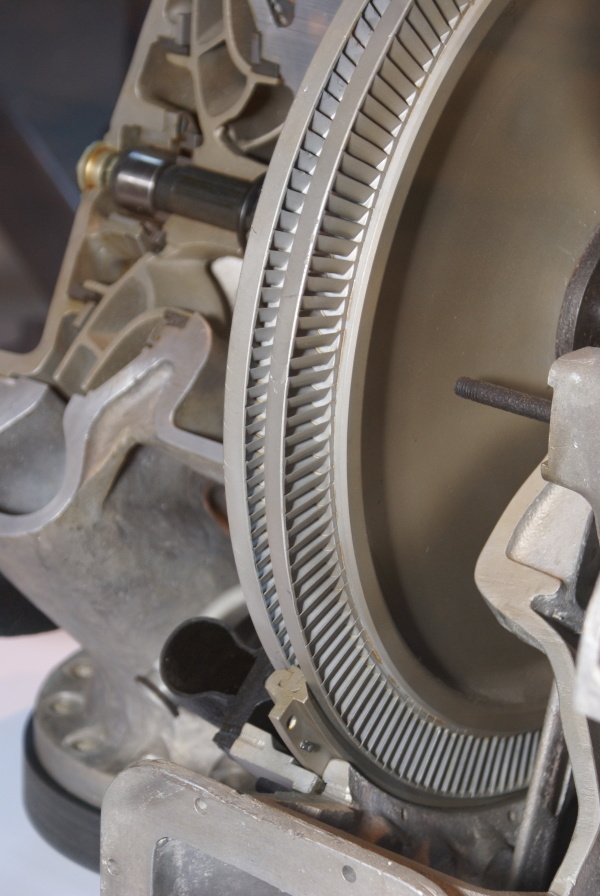
Dual blade V2 turbo-pump steam turbine rotor
Dual blade V2 turbo-pump steam turbine rotor
This image shows a cutaway of an A4-V2 turbo-pump. The section reveals the Curtis type 2-stage steam-turbine rotor and you can also see part of the stater inserted between the blades (bottom middle) and the adjacent steam distribution pipe (black open pipe on stater’s immediate left). Top left, a centrifugal pump rotor can be seen – cut through, it shows a multi-splined shaft running through the centre, simple bearing and end-cap.
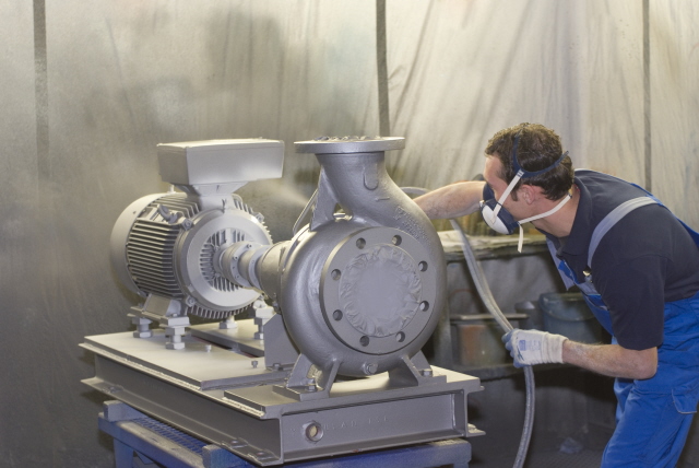
Family photo? Electric volute case centrifugal pump by KSB
Family photo? Electric volute case centrifugal pump by KSB
Electric industrial volute case centrifugal pump by Klein Schanzlin & Becker. This image highlights the ‘genetic’similarity and family resemblance between KSB’s current and historical product range and the visible features of the A4-V2 missile Turbo-Pump (TP). Assembly is shown being spray painted.
V2 rocket A Stoff (LOX) pump casing 5740
V2 rocket A Stoff (LOX) pump casing 5740
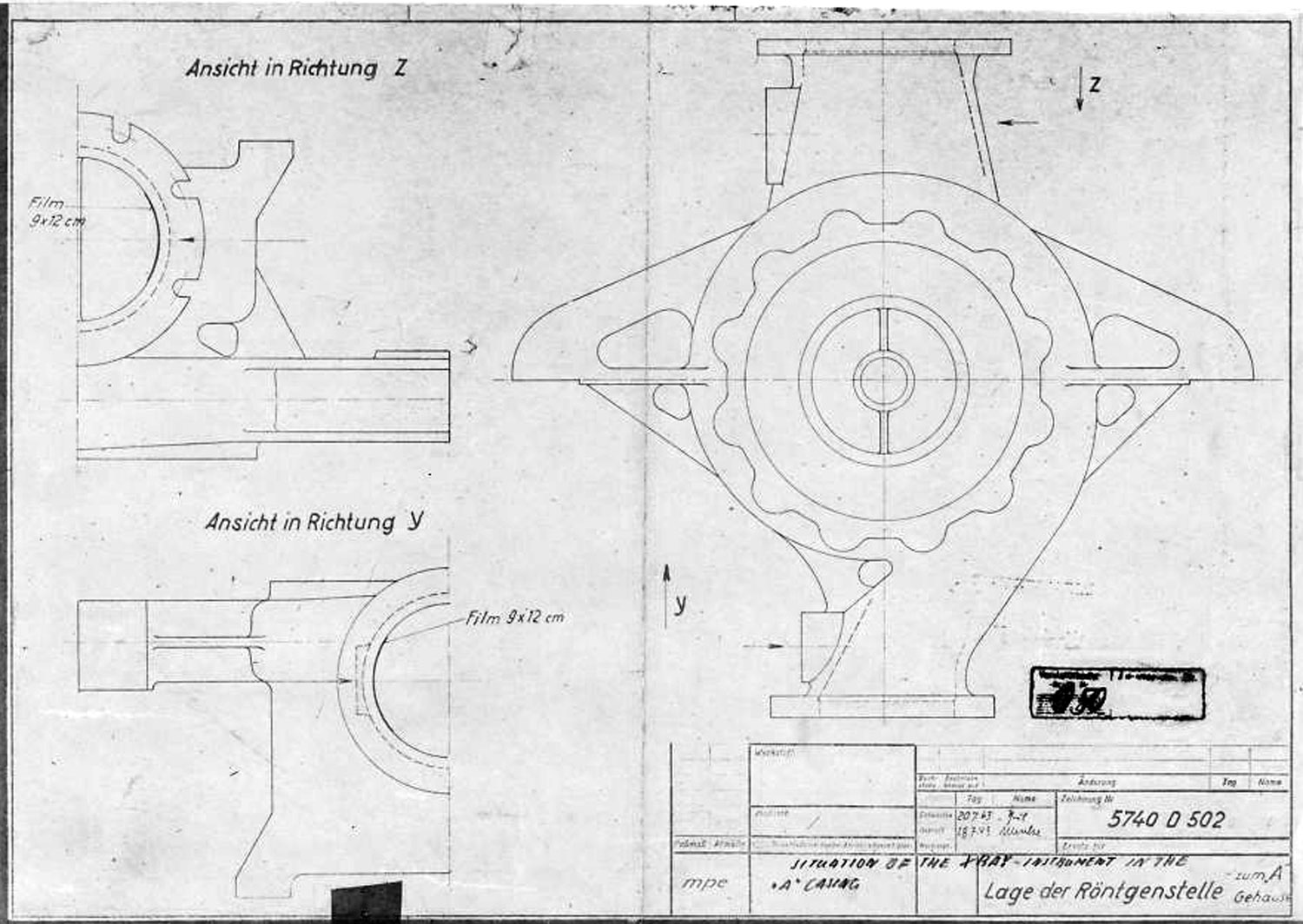
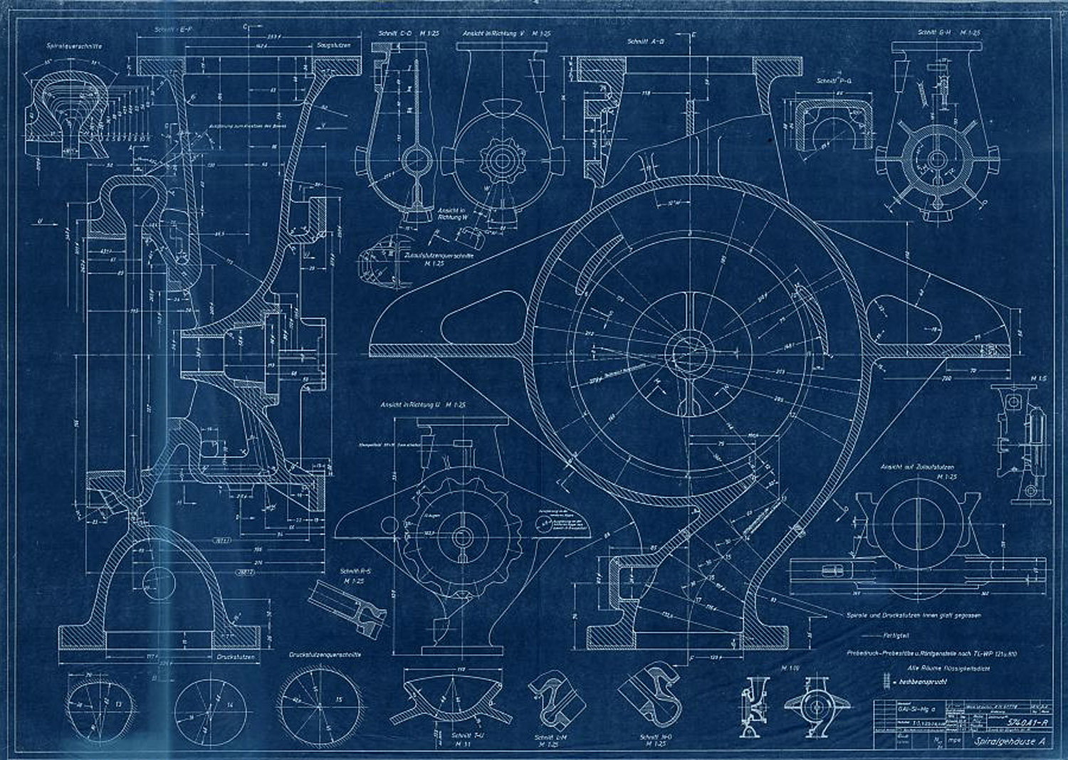
A Stoff (liquid oxygen) pump casing diagram showing stress points that require X ray quality control photography before use. The diagram shows the specific locations where photographic film is to be placed for X-ray analysis.
Turbo-Pump (Z 935 A) cutaway presentation Sept 1942
Turbo-Pump (Z 935 A) cutaway presentation Sept 1942
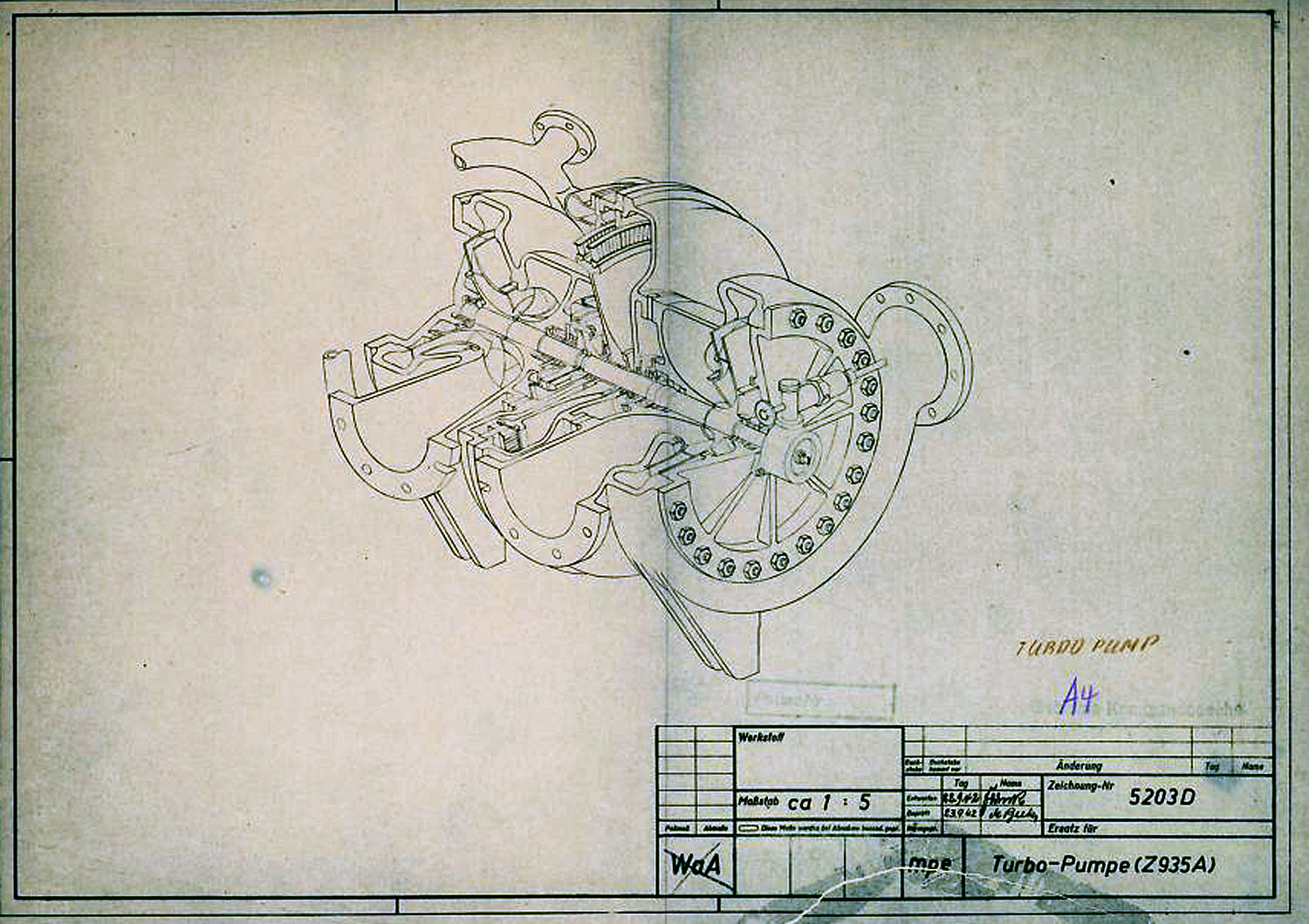
In this diagram the V2 Turbo-pump is shown in a cutaway presentation and rotated 90 degrees counter clockwise. The B stoff (fuel) pump is nearest the viewer – the over-speed device can be seen on the B stoff pump’s case end-plate. The low pressure inlet ports our shown to the left, and high-pressure outlet ports are on the right. The steam distribution manifold can be seen at the furthest point from the viewer – the steam inlet pipe flange can also be seen. The feed pipe from the steam generator attaches to thus flange.
A4-V2 Steam rotor blade design and position 5742 B 1944
A4-V2 Steam rotor blade design and position 5742 B 1944
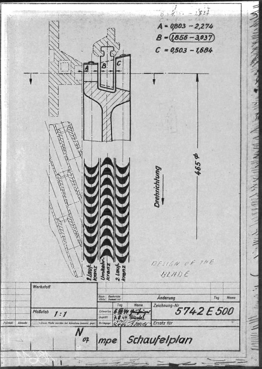
This mpe* drawing from 1945 shows the individual steam buckets or blades (labeled A and C) mounted to the rim of the rotor disk. As well as the fixed (i.e. stationary) stater blade B, positioned such that blades A & C can pass either side of it. The steam expansion is well shown by the increasing surface area of the blades from A to C, and growing larger, from left where the high pressure super heated steam enters the turbine, to right where it exits the blade pathway and passes in to the exhaust outlet. The lower graphic shows the way the super-heated high pressure steam is passed from the initial A blade and deflected by the reversed B stator blade for its energy to to be harvested for a second time by the C rotor blade. * mpe is the secret three letter armament code for Karlshagen, Werk Nord (North Works).
Oddesse Turbo-Pumpe 1940 Br 75 / 20
Oddesse Turbo-Pumpe 1940 Br 75 / 20
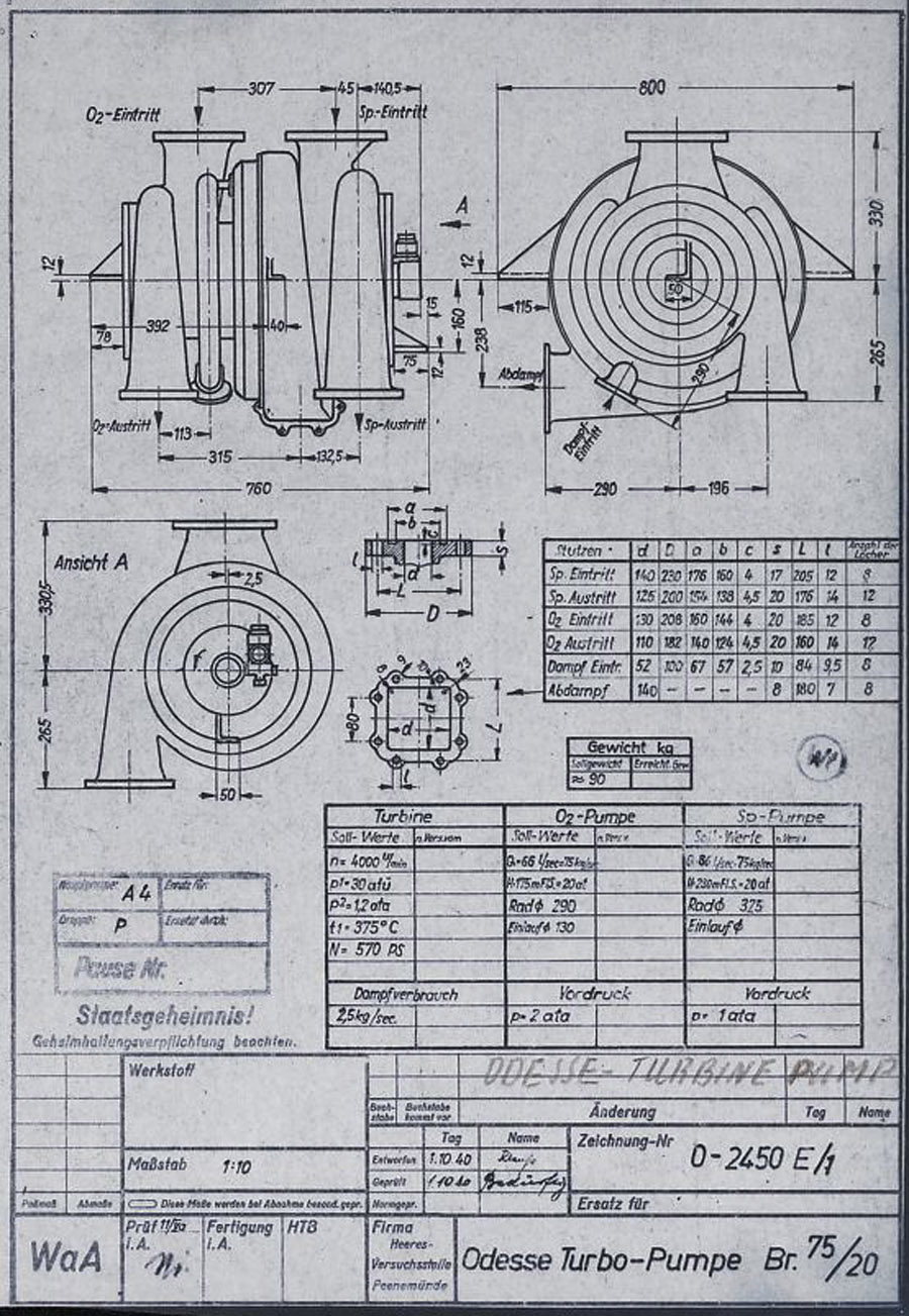
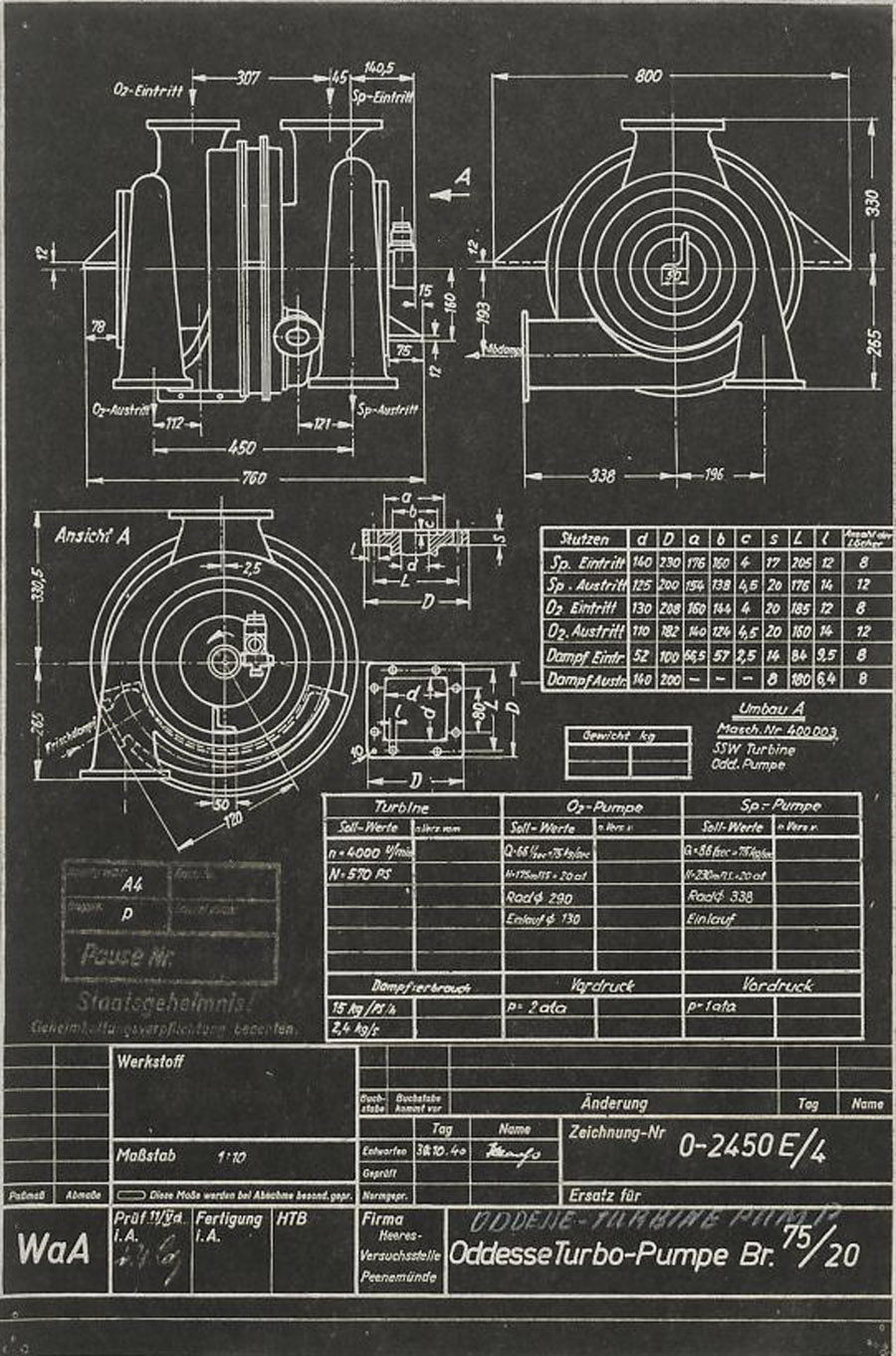
This HVP technical drawing from October 1940, shows a proposal from the Oddesse company – the full title of this company is KLEIN SCHANZLIN ODDESSE GmbH. Klein, Schanzlin & Becker A.G. (waffenamt code: ebb) took over Oddessa in 1929 and the company became formally known as KLEIN SCHANZLIN-ODDESSE GmbH (code ebc) in 1939. (NB: The company name has nothing to do with a similar sounding place name Odessa. The Oddesse trading name was formed from the partnership of English engineer Oddie, and German businessman Hesse.). The dual centrifugal turbo-pump shown in the drawing is a variant of a high pressure fire-fighting pump manufactured by Oddesse. Note the off-center outflow ports – not also that the outlet flanges are still level at this stage. Note also the incorrect spelling of the company name in the details panel lower right. (Digipeer.de image)
Oddesse Turbo-Pump Br 75 / 20
Oddesse Turbo-Pump Br 75 / 20
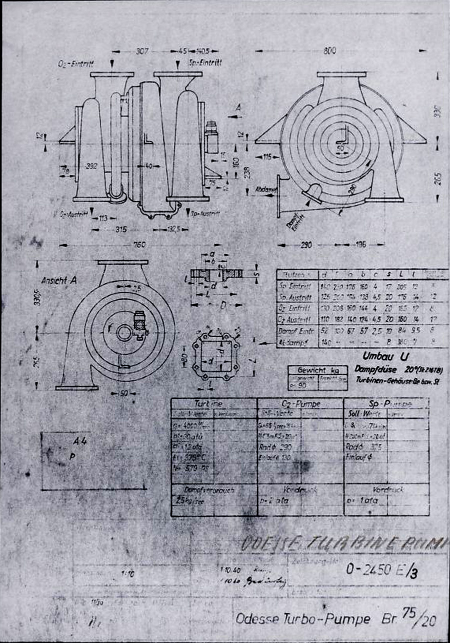
Another HVP technical drawing from later in October 1940, shows further data from the KLEIN SCHANZLIN ODDESSE (ebc) company A4-V2 turbo-pump project. See previous image for company details. The dual centrifugal turbo-pump shown in the drawing is a variant of a high pressure fire-fighting pump manufactured by Oddesse. Note the off-center outlet ports. Note also the corrected spelling of the company name in the details panel lower right (see previous Oddesse image) and the small note below the top table that indicates that the pumps are from Oddesse (ODD) and the turbine from a company indicated as SSW. (Digipeer.de image)
Klein Schanzlin Oddesse Turbo-Pump schema 1940
Klein Schanzlin Oddesse Turbo-Pump schema 1940
Signatur FA 014/21241 (Digipeer.de image)
Turbopump Lieferfirma KSB, Frankenthal (vorläufiges Maßblatt Serie 0)
Turbopump Lieferfirma KSB, Frankenthal (vorläufiges Maßblatt Serie 0)
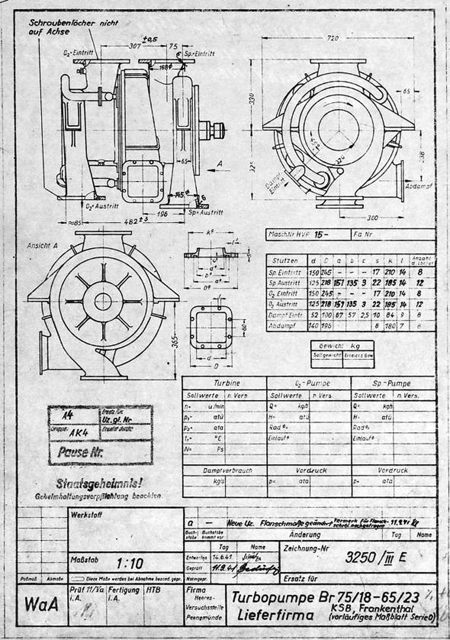
V2 rocket turbo-pump preliminary dimension sheet for O series, drawing. Many of the final elements of the turbo-pump design can be seen in this ‘preliminary’ drawing and table form 1941. The word lieferfirma in the data box btm right mean supply company – and this is indicated to be KSB or Klein Schanzlin & Becker AG, Frankenthal. Signatur FA 014/14769
(Digipeer.de image)
Laufrad A (Rohteil) zur A-Pumpe nach Zeichnungsnummer 5740 B Ausführung A und B [lt. Titelerfassung …
Laufrad A (Rohteil) zur A-Pumpe nach Zeichnungsnummer 5740 B Ausführung A und B [lt. Titelerfassung …
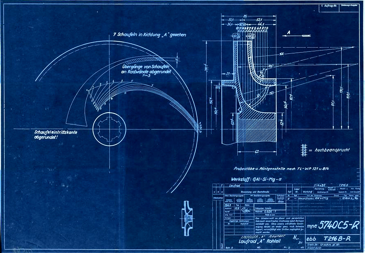
Centrifugal impeller for A or liquid oxygen (LOX) pump. The drawing originated in Aug 1943 and was superseded in December 1944. A key to the image hatching can be seen with the label ‘Hochbeansprucht’ which in English means Highly Stressed. Next to the drawing numbers two secret three letter armament codes can be seen indicating the ‘origination’ of the document. The top one mpe = Heimat Artillerie Park 11 (HAP or Army Artillery Range). The lower code ebb = Klein Schanzlin & Becker AG, Frankenthal.
Signatur FA 014/02542 (Digipeer.de image)
Gehäusedeckel A zur A-Pumpe nach Zeichnungsnummer 5740 B Ausführung A und B
Gehäusedeckel A zur A-Pumpe nach Zeichnungsnummer 5740 B Ausführung A und B
Signatur FA 014/02537
Abmessungen: 42,9×59,8
A-Pumpe zur Turbopumpe nach Zeichnungsnummer 5800 A Blatt 1 und 2 (Montagezeichnung)
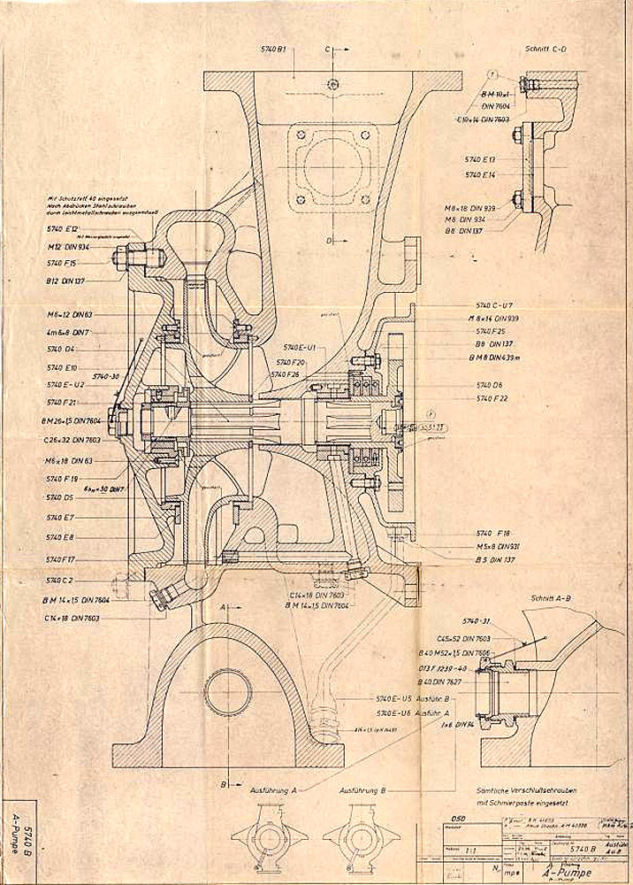
A-Pumpe zur Turbopumpe nach Zeichnungsnummer 5800 A Blatt 1 und 2 (Montagezeichnung)
Signatur FA 014/02534
Abmessungen: 60,5×82,9
F1: Fertigungshalle Eins
3305D Close-up of nebular cone & cooling jets
3305D Close-up of nebular cone & cooling jets
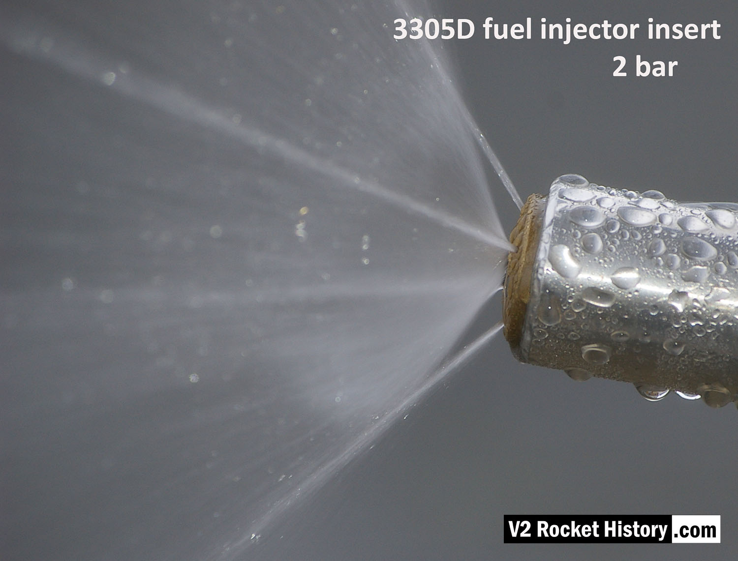
Image shows a correctly formed nebular cone attended by a fine mist. the four injector cooling jets are well shown, and although fluid beading can be seen on the face of the injector, there is insufficient liquid to cause dripping.
3305D Water Test Comparison
3305D Water Test Comparison
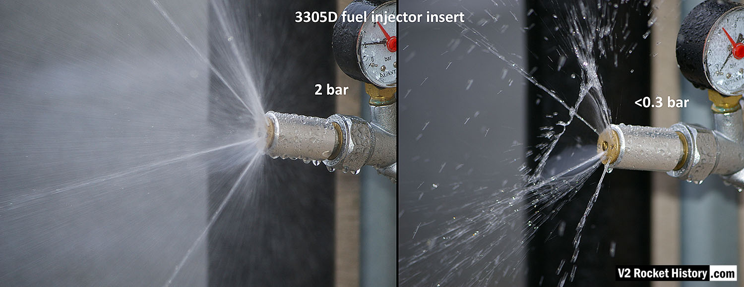
3305D injector insert showing comparison nebular and jet stream pattern with high and low pressure. Top image shows correct hollow cone-shaped aerosol effect, from central 6mm orifice, that is also creating a fine mist around and within the cone, and steady steams emanating from cooling pores. Bottom image shows the effect of reduced pressure: a dropping poorly formed cone, composed of larger slower moving droplets, and a tendency for the thicker spray to combine and cause ‘dribbeling’ with much fluid failing to clear the injector face – unlike the image above, where the injector face is clear of drips.
3305D Water Test Comparison 2
3305D Water Test Comparison 2
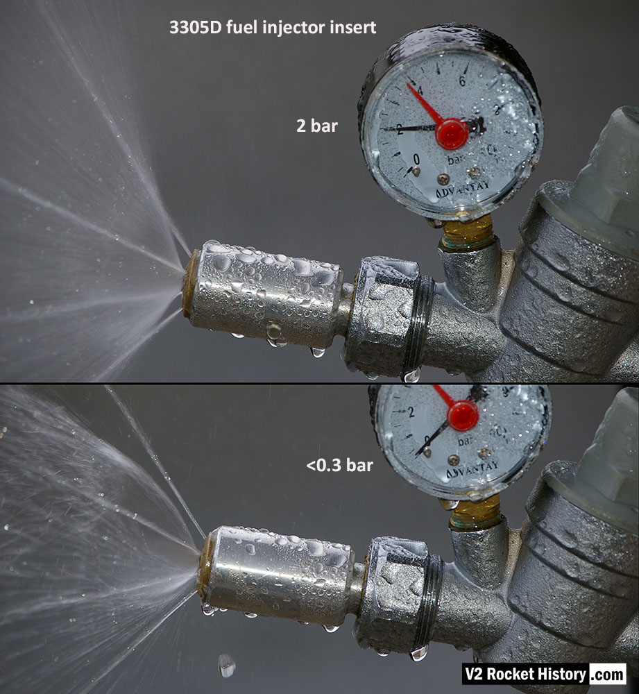
3305D fuel njector insert showing comparison nebular and jet stream pattern with high and low pressure. Left image shows correct hollow cone-shaped aerosol effect from central 6mm orifice, that is also creating a fine mist around and within the cone, and 4 steady steams emanating from cooling pores. Right image shows the effect of reduced pressure: a dropping poorly formed cone, composed of larger slower moving droplets, and a tendency for the thicker spray to combine and cause ‘dribbeling’ with much fluid failing to clear the injector face.
3305D Water test nebular pattern
3305D Water test nebular pattern
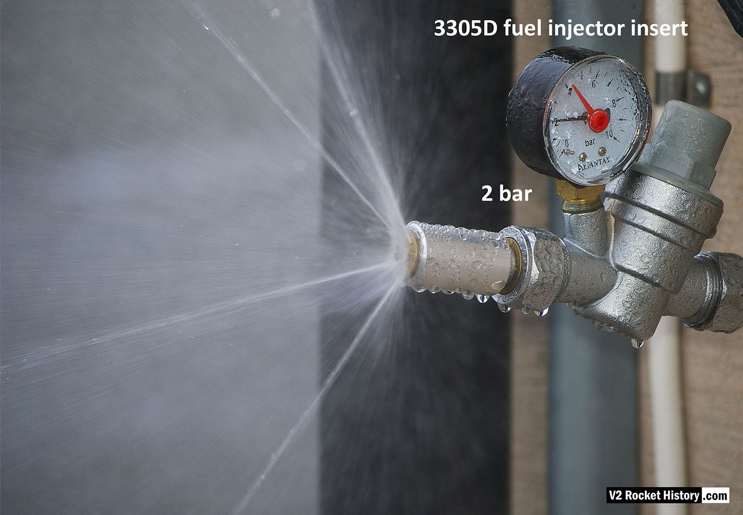
3305D fuel injector insert showing swirl cone nebular, and 4 steady steams emanating from cooling pores.
Fuel injector 3304D water test comparison
Fuel injector 3304D water test comparison
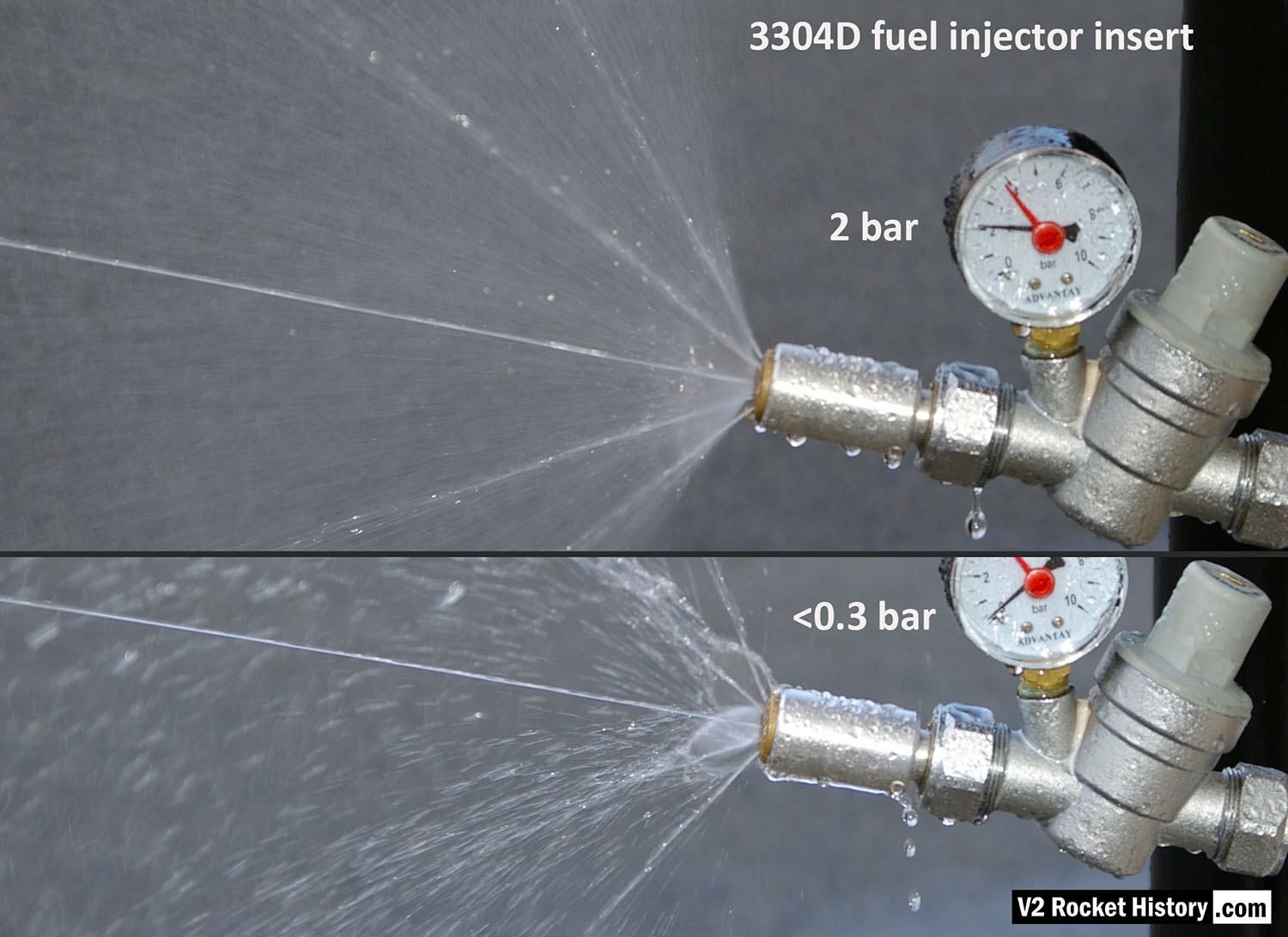
3304D higher volume injector insert (with central jet) showing comparison nebular and jet stream pattern with high and low pressure. Top image shows correct hollow cone-shaped aerosol effect from central 6mm orifice, that is also creating a fine mist around and within the cone, and strong single central (non-swirl) jet can be seen as well as 4 steady steams emanating from cooling pores. Bottom image shows the effect of reduced pressure: a dropping poorly formed cone, composed of larger slower moving droplets, and a tendency for the thicker spray to combine and cause ‘dribbeling’ with much fluid failing to clear the injector face. The appearance of central jet however seem largely unchanged.
3304D Water test nebular pattern showing central jet
3304D Water test nebular pattern showing central jet
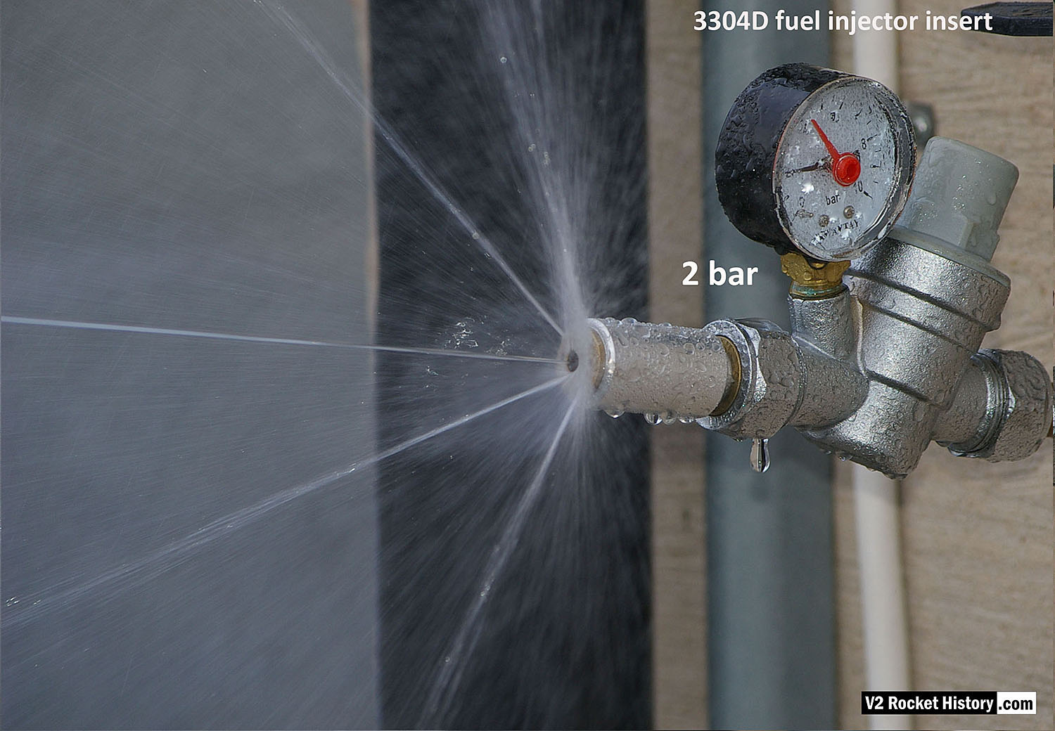
3304D higher volume fuel injector insert (with three inlet apertures: 2 swirl, 1 jet) showing swirl cone nebular, steady central jet, and 4 steady steams emanating from cooling pores.
Jet from 2mm drilled fuel feed hole
Jet from 2mm drilled fuel feed hole
Each burner cup of the V2 rocket engine injector system has forty-four brass inserts, but each cup also has twenty-four 2mm diameter plain holes, 30 deg apart, drilled into the cup’s central wall. To mimic this for testing purposes, we created a brass insert that has a base with just a 2mm central hole. The base is sized to be consistent with the 4 to 5mm cup wall. V2RH image

3305D Water Test Pattern
3305D Water Test Pattern
3305D injector insert showing larger low-velocity droplets and ‘dribbly’ performance due to insufficient pressure. The cone shaped aerosol is not functioning. Broken streams can be seem emanating from the four cooling pores.
Injector test rig showing pin wrench to fit inserts
Injector test rig showing pin wrench to fit inserts
Single fuel injector water test rig showing a 3305D bress insert about to be tightened home using a pin-wrench. V2RH image

V2 fuel injector Insert test rig
V2 fuel injector Insert test rig
Single nozzle insert test rig used by V2 Rocket History to test spray shape and volume at supply pressures consistent with fuel pressures specified for the injector head of summer 1944. The test system features an adjustable pressure regulator and fluid pressure gauge. For test purposes the device was simply connected to a relatively high pressure mains water supply. And although water does not have the same viscosity of the 75% Ethenol to 25% water mix of the V2’s fuel it was considered close enough by the German technicians, who regularly used plain water as a substitute when testing issues related to furl flow rather than combustion. A 2131E fuel injector insert is shown installed in the holder at the front of the rig, but as the thread was the same on all inserts the nozzle can be changed for other models easily with aid of a pin spanner. See video for a demonstration of this simple test system.

Test Rig With E Type Insert
Test Rig With E Type Insert
Single nozzle insert test rig used by V2 Rocket History to test spray shape and volume at fluid supply pressures consistent with fuel pressures specified for the injector head of summer 1944. A 2131E fuel injector insert is installed in the holder at the front of the test rig, but as the thread was the same on all inserts the nozzle can be changed for other models easily with aid of a pin spanner. See video for a demonstration of this simple test system.

Fuel injector flow test results
Fuel injector flow test results
The chart shows water delivery in litres per minute per injector
| Album | Testing fuel injectors |
| Categories | Combustion, Propellant flow |

V2 Fuel Injector insert test stock
V2 Fuel Injector insert test stock
V2 rocket engine fuel injector inserts – a part of our collection used for the water tests with various types shown. The tool shown is a pin-wrench used to fit the inserts into the test apparatus. V2RH collection image

Fuel Injector insert showing aperture details
Fuel Injector insert showing aperture details
Standard fuel injector inserts for production series 18-pot injector head. Insert 1 (3304D/3305D) shows four thin wires demonstrating the angles of all four ‘cooling’ pores. Insert 2 (3305D/2131E) has two 1.3mm twist drill showing the edge bores for the gyroscopic swirl inlets. Insert 3 (3305D) shows another view of the cooling pore angle and origin. V2RH image

V2 Fuel Injector 2131E
V2 Fuel Injector 2131E
V2 Fuel Injector insert: part code 2131E from injector pot echelon A (nearest to LOX spray head). The push-together two part construction of the insert is shown here. The two parts were pushed together in a specially shaped tool set that compressed the thin skirt on the female part into a recess cut into the male part. The failure test for this component required that the mated parts resist a separating force of 300kg. The two part design was dictated by the small size of the 2mm exit orifice and the funnel shaped introduction to the exit orifice. In the case of the other three standard inserts, the large 6mm exit orifice allowed a sub 6mm milling cutter, with a thin support shaft and a top chamfer, to be used in such a way that the area below the exit orifice could be undercut to create an injector cavity with a diameter larger than the 6mm entry point.
Swirl nozzle insert set 2
Swirl nozzle insert set 2
Fuel injector inserts for production series 18-pot injector head showing general shape and thread position. For further details see associated image. The lowermost insert have been halved to reveal the cavity shape, orifice edge, inlet and cooling apertures. V2RH image
Equipment bays
V2 missile on rail wagon showing control bays
V2 missile on rail wagon showing control bays
Incomplete V2 missile on rail transporter. All 4 control compartments are well shown. The fuel tank connection pipe can be seen but not much else. All of the control equipment has been removed. Plainly visible is the chicken wire holding the fiber wool tank insulation in place. Today this would be called ‘Galvanised hexagonal network restraining matrix, and be supplied by a blue chip Aerospace company for $800 per square inch. In the 1940s, it was just chicken wire at a 2 dollars for a 100 ft roll.
| Album | Equipment bays |
Control compartments 1 & 4
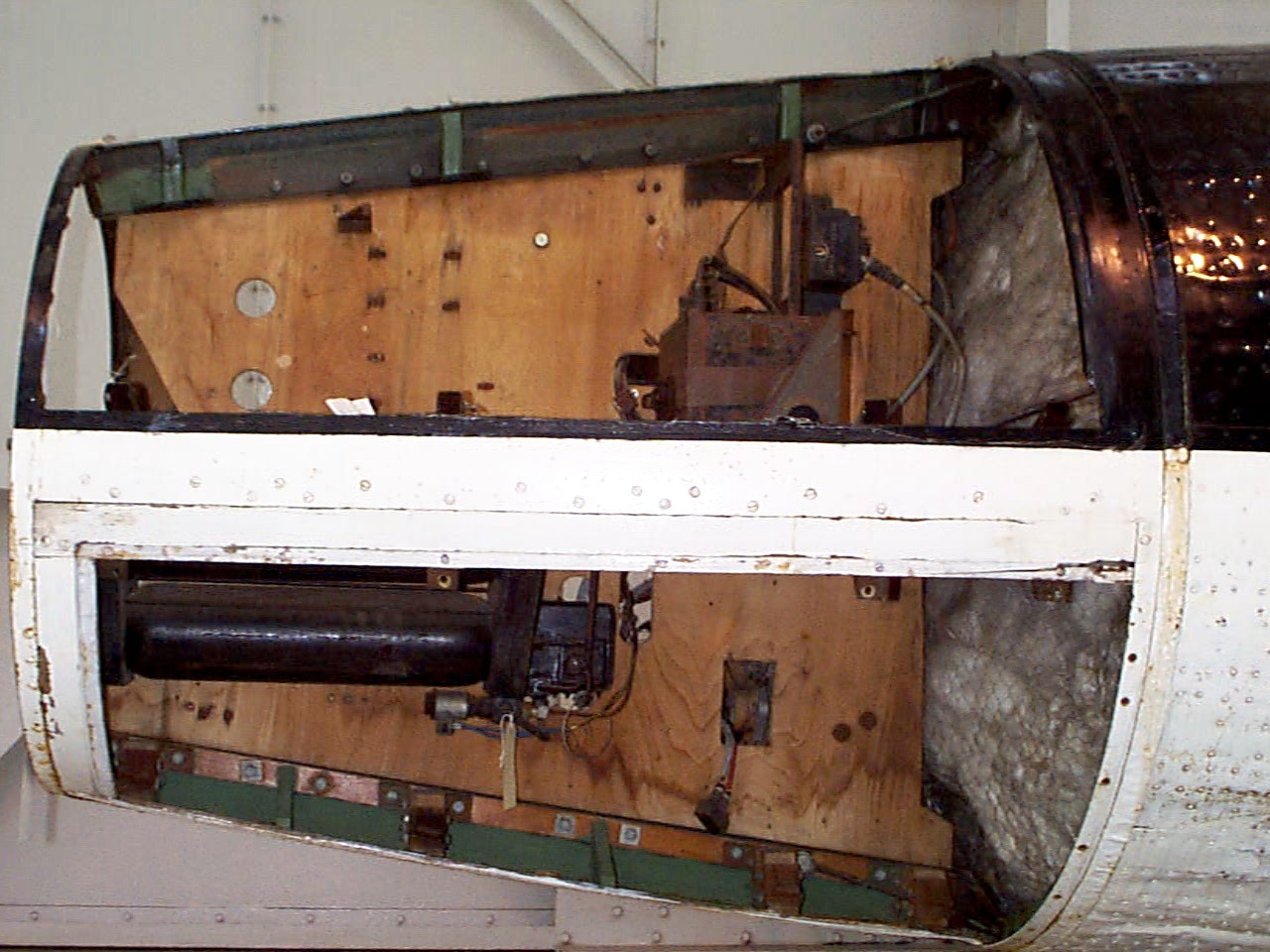
Control compartments 1 & 4
Control compartments 1 (upper) & 4 (lower) Image copyright Imperial War Museum
| Album | Equipment bays |
| Category | Missile guidence |
Control compartment 3
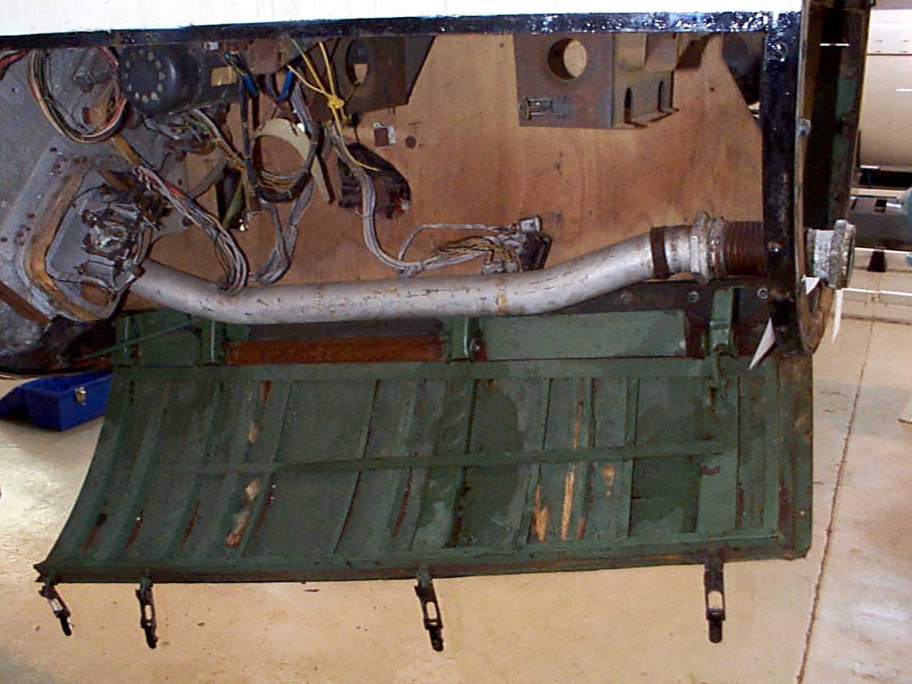
Control compartment 3
Control compartments 3 showing gyro mounting platform with two gyros and DC motor driven 3 phase AC voltage generator. The alcohol tank pressurisation pipe is also shown running through the equipment bay (large silver coloured pipe). Image copyright Imperial War Museum
| Album | Equipment bays |
| Category | Guidence |
Control compartment 1
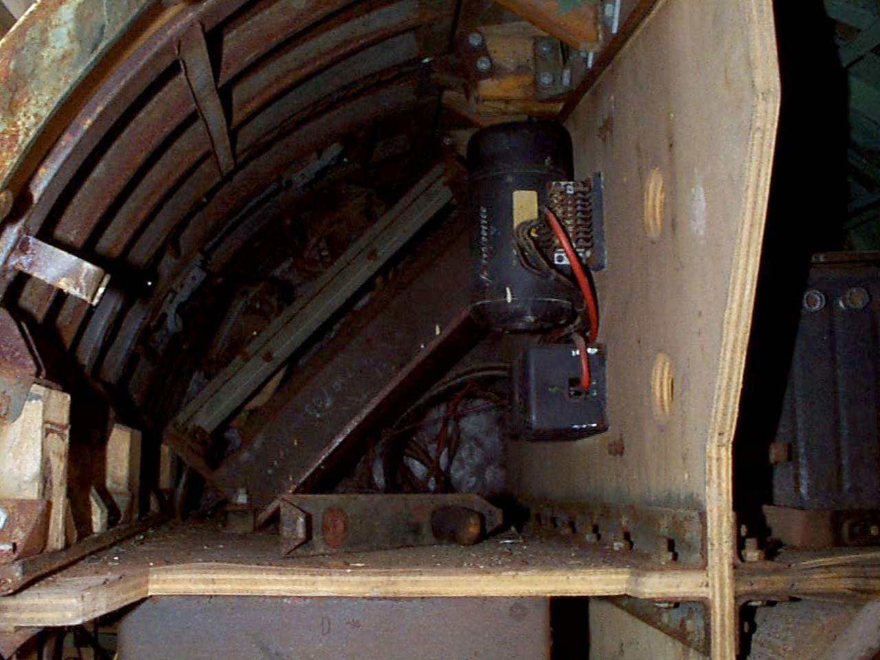
Control compartment 1
Control compartments 1. Image copyright Imperial War Museum
| Album | Equipment bays |
| Category | Electrical connection |
Control compartment 2
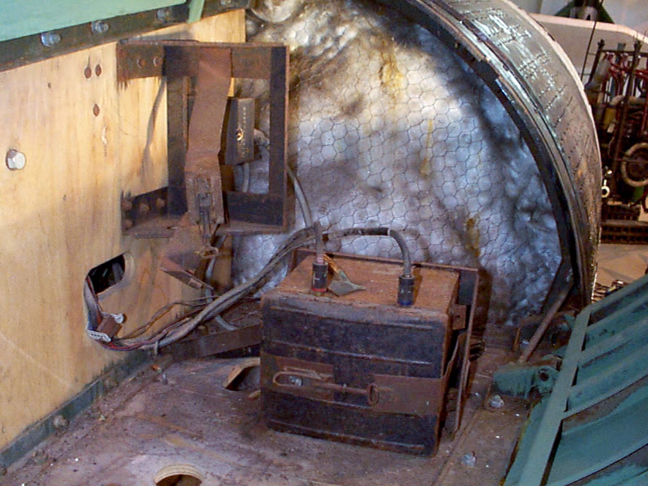
Control compartment 2
Control compartment 2 showing plywood separation panels, Oemig umformer (DC to 3 phase AC voltage generator), and voltage frequency control box. Towards the rear the ground connection plugs can just be seen and the mechanism of the cable release trap door (see cat flap!). Image copyright Imperial War Museum
| Album | Equipment bays |
| Category | Electrical connection |
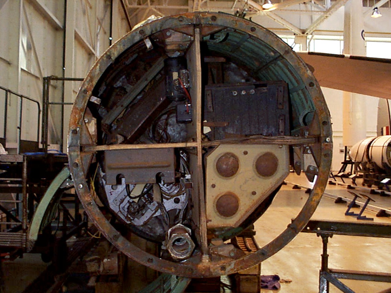
Control compartments – all 4 top view
Control compartments – all 4 top view
Control compartment 1 top right, 2 top left, 3 bottom left, and 4 bottom right. The fuel tank pressurisation pipe upper connection point is well shown at about 6 o’clock (compartment 3) and just above and to the right the upper plate of the air (N) tank rack (tan colour). Image copyright Imperial War Museum
showing plywood separation panels, Oemig umform
| Album | Equipment bays |
Missile guidance equipment
Images of guidance and missile control equiment


Missile guidance equipment
Images of guidance and missile control equiment
LEV-3 Horizont and Vertikant gyroscope system 1940
category:Missile guidence, Sub-assemblies


Description
LEV-3 V2 missile gyroscope system with mounting plate. The third component of this system, the Muller gyroscopic accelerometer, is missing – the 2x mounting points can be seen on the right-hand side of the mounting plate.
Location
