

Archives: Gmedia Albums


The Enigmas
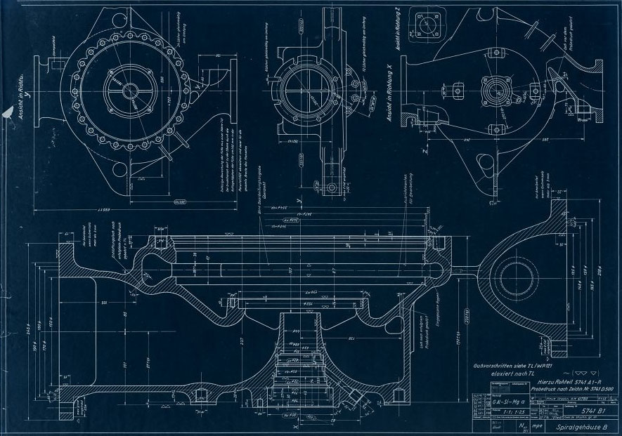
Drawing 5741 B1 – Fuel (B) Pump Spiral-housing
Drawing 5741 B1 – Fuel (B) Pump Spiral-housing
Drawing 5741 B1 mpe – Fuel (B) Pump Spiral-housing with dimensions. Drawing origin 18 July 1944, revised to new drawing (AM41780) 11 Jan 1945. (Digipeer.de image)
| Album | V2 rocket turbo-pump |
| Category | Turbo-pump |
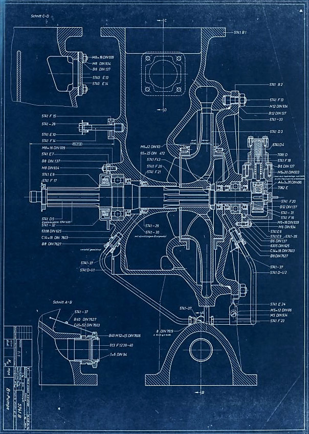
Drawing 5741 B – Fuel (B) Pump Assembly – Part Numbers
Drawing 5741 B – Fuel (B) Pump Assembly – Part Numbers
Drawing 5741 B mpe – Fuel (B) pump assembly showing part/drawing numbers. Drawing originates 20 July 1944 and revised with new number (AM41780) 16 Jan 1945. (Digipeer.de image)
| Album | V2 rocket turbo-pump |
| Category | Turbo-pump |
V2-Turbine: steam-distributor-revision
V2-Turbine: steam-distributor-revision
Animation highlighting just one of many revisions to the turbo-pump that occurred at an accelerating rate between August 1943 and late 1944 as the missile moved from development to full production, and finally use in combat. (Digipeer.de images: animation RJD)
| Album | V2 rocket turbo-pump |
| Category | Turbo-pump |
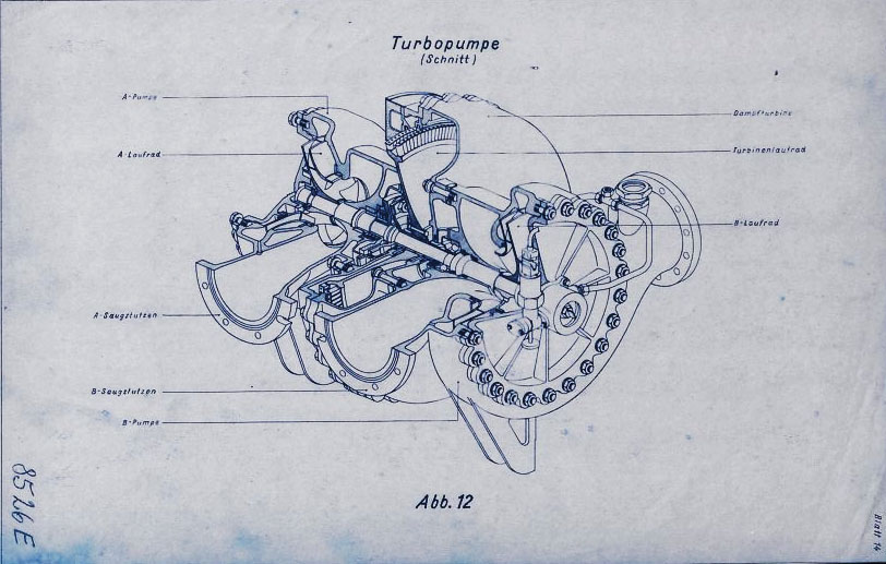
Turbopump (cut-away) – Figure 12
Turbopump (cut-away) – Figure 12
Drawing 8526 E mpe 1944: Turbo-pump training presentation image showing cutaway. (Digipeer.de image)
| Album | V2 rocket turbo-pump |
| Category | Turbo-pump |
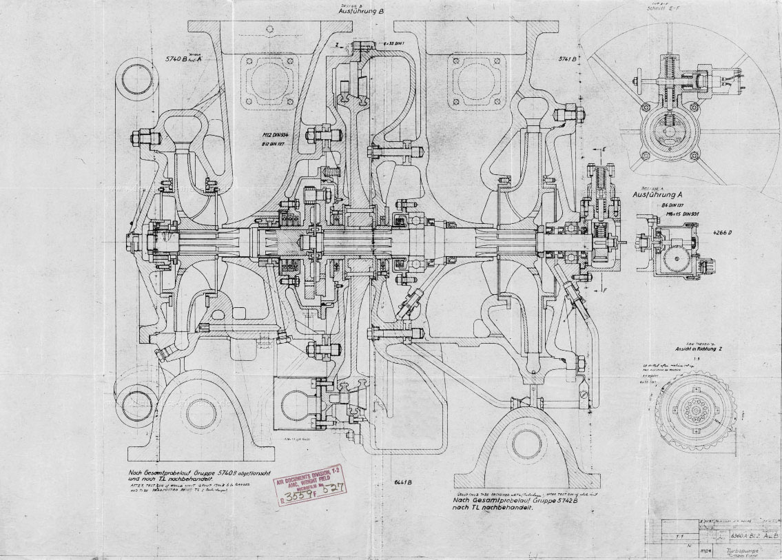
Drawing 6380 A – Turbo-pump Assembly 08 Aug 1944
Drawing 6380 A – Turbo-pump Assembly 08 Aug 1944
Drawing 6380 A – Turbo-pump Assembly 08 Aug 1944. (Digipeer.de image)
| Album | V2 rocket turbo-pump |
| Category | Turbo-pump |
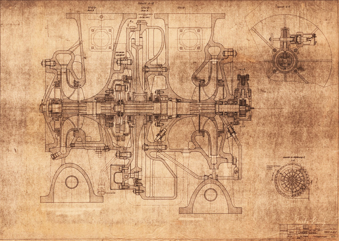
Drawing 5800 A – Turbo-pump Assembly 1 March 1944
Drawing 5800 A – Turbo-pump Assembly 1 March 1944
Drawing 5800 A – Turbo-pump Assembly 1 March 1944. (Digipeer.de image)
| Album | V2 rocket turbo-pump |
| Category | Turbo-pump |
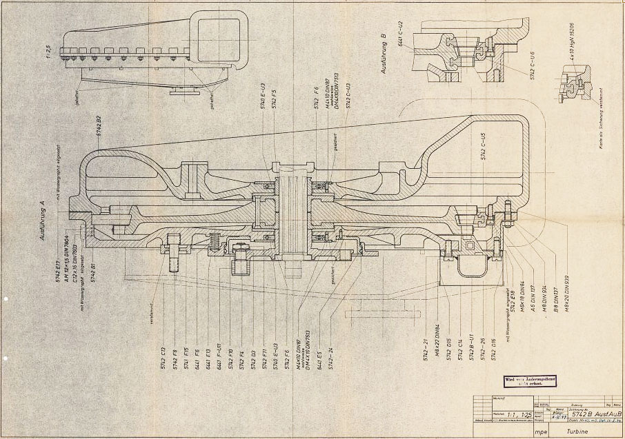
Drawing 5742 B – Steam Tubine Assembly Part Numbers
Drawing 5742 B – Steam Tubine Assembly Part Numbers
Drawing 5742 B – Steam Tubine Assembly showing part/drawing numbers. (Digipeer.de image)
| Album | V2 rocket turbo-pump |
| Category | Turbo-pump |
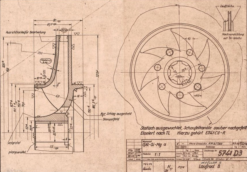
Turbo-pump drawing: 5741 D3
Turbo-pump drawing: 5741 D3
Drawing Number: 5741 D3 showing B (fuel) pump centrifugal impeller mpe drawing dated April 1944. mpe original drawing (Digipeer.de image)
| Album | V2 rocket turbo-pump |
| Category | Turbo-pump |
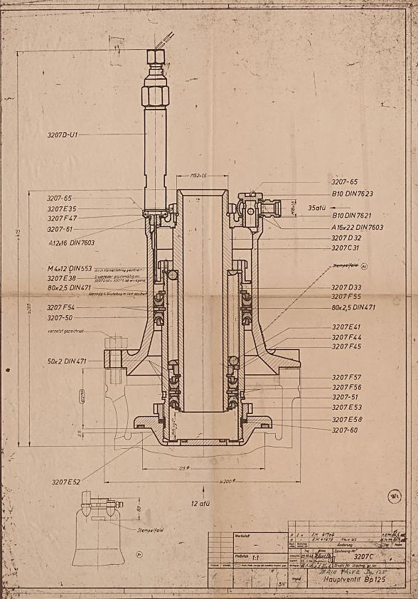
Drawing of Main Fuel Valve 3207C
Drawing of Main Fuel Valve 3207C
Original mpe 1944 drawing number 3207 C of main fuel valave. (mpe = Heimat-Artillerie-Park Karlshagen, Werk Nord Peenemünde).
| Album | Valves |
| Category | Propellant flow |

1000 kg 4B engine 1940
1000 kg 4B engine 1940
The injector head section of the 4B 1000kg thrust rocket engine is a precursor to the injector pot or ‘pre-chamber’ design used later for each of the 18-pots of the 25-ton V2 rocket engine. Most of the essential ingredients are shown in this drawing from 1940. Drawing no 1848E Deutsches Museum München online archive ref FA 014/12829

V2 Rocket standard screw-fit fuel Injector Insert 3304D 1944
V2 Rocket standard screw-fit fuel Injector Insert 3304D 1944
HAP11 drawing of standard 3304D fuel injector screw insert. showing details of primary swirl cavity and orrifice and all additional apertures including the four small cooling pores. HAP11 (Heimat-Artillerie-Park 11, AKA armament code: mpe), drawing number 4554D, Deutsches Museum München

HVP Drawing of diffuser system 1939
HVP Drawing of diffuser system 1939
HVP drawing no 1203D showing burner cup ‘diffuser system’ disposition for 19-pot head (at this stage the 25 ton thrust injector head had nineteen so called ‘pre-chambers’ or pots as no central fuel valve was present). HVP drawing dated 1939.

Drawing of fuel nozzle Insert 1113E 1939
Drawing of fuel nozzle Insert 1113E 1939
Drawing from the Army Experimental Station Peenemünde dated 1939. The specification describes an insert template that could be used for a range of outlet and inlet orifice sizes. The German text beginning (eingedrehte …) translates as ‘Center-line of screw used for holes to be drilled later’, and the hole dimensions are not specified on this document. HVP drawing number 1113 E, Deutsches Museum München
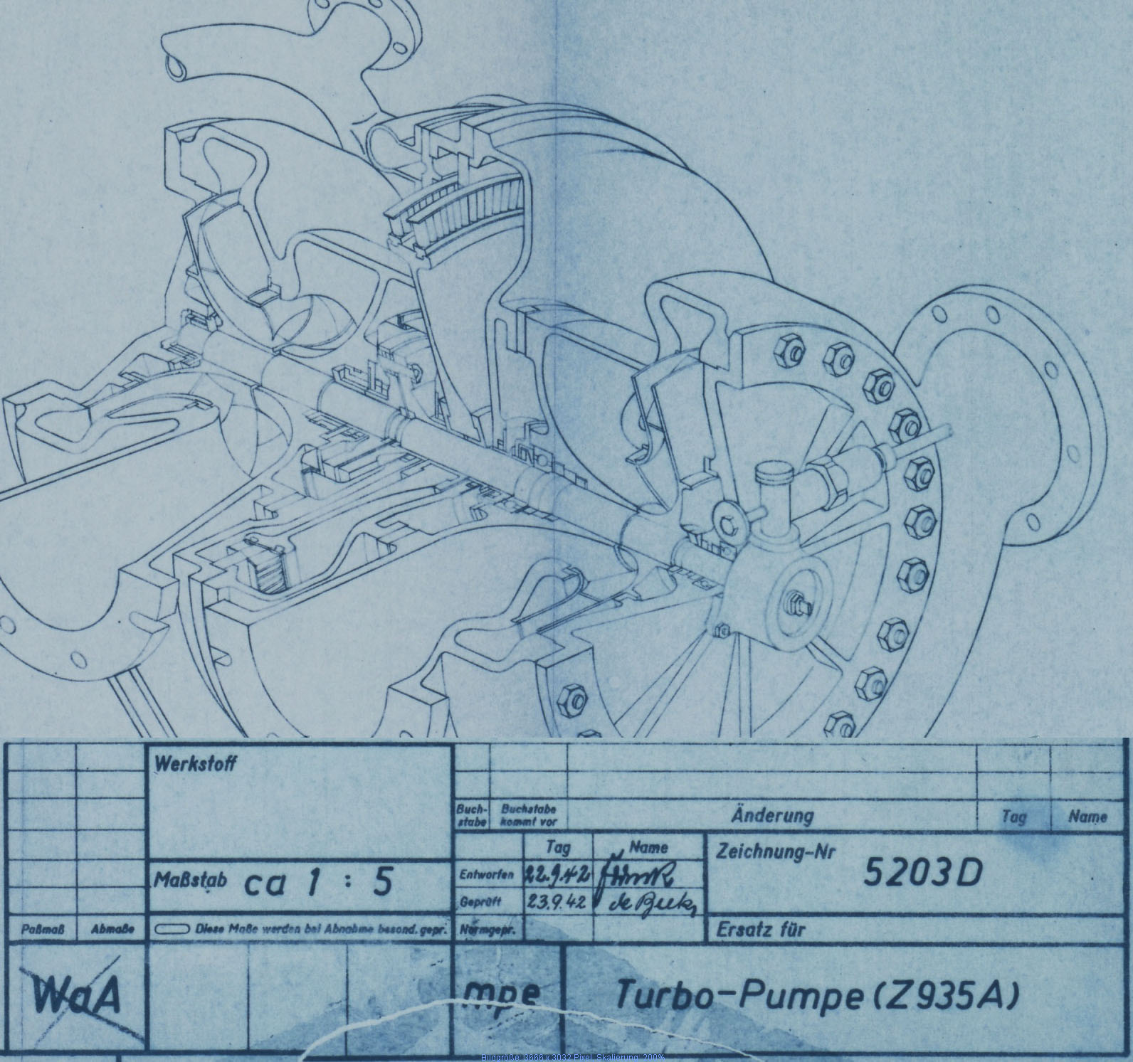
General view drawing V2 rocket Turbo Pump 1942
General view drawing V2 rocket Turbo Pump 1942
Sectioned general assembly view of the V2 turbo-pump (TP) dated September 1942. This image has been edited to show TP and document data closer together than the original.

Fuel injector specifications for 25 Ton 18-pot engine
Fuel injector specifications for 25 Ton 18-pot engine
Specification for fuel injector inserts showing orifice size, type, and A to E echelon position. Peenemünde document dated 30th October 1943. Of note on this document is the combination of high and low volume injector inserts (3304D and 3305D) in the echelon E position of the 12 cups comprising outer ring I. It shows that each cup or pot on this outer ring had 16 inserts at the lowermost position E with 12 of the inserts with three inlet apertures (3305D) and 6 with only two inlet apertures (3304D being lower flow volume) positioned in the segment covering 165 degrees and closest to the outside edge of the head. HAP11 (Heimat-Artillerie-Park 11, AKA armament code: mpe), drawing number 4554D, Deutsches Museum München
F1: Fertigungshalle Eins
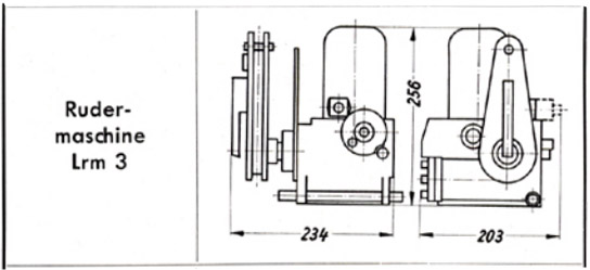
Askania rudder servo ‘Rudermaschine LRM 3’
Askania rudder servo ‘Rudermaschine LRM 3’
A schematic drawing of the Askania rudder servo ‘Rudermaschine LRM 3’showing the critical compact dimentions of the device making it ideal for retro fit projects for smaller aircraft.
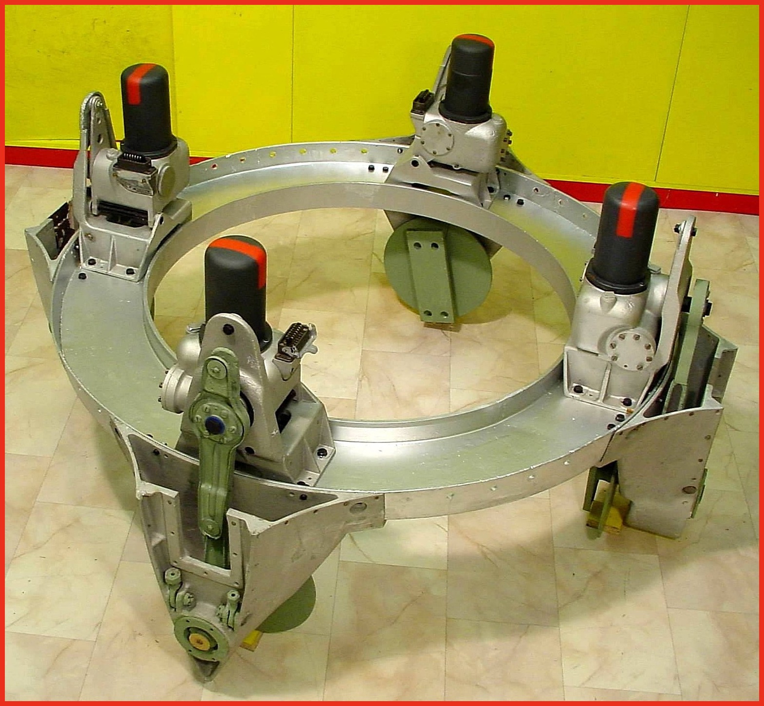
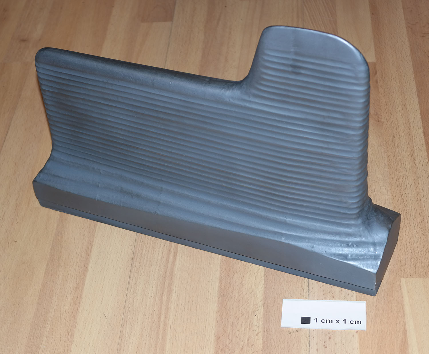
A4-V2 thrust ring with control servos (Abtriebsring) ©THBC
A4-V2 thrust ring with control servos (Abtriebsring) ©THBC
Photo shows cast aluminium thrust ring with electro-hydraulic servos in position. Note different crank lever shapes (pale green arm on servo) for fins 1/3 and 2/4 This excellent restoration is the work of Horst Beck. Photo copyright: The Horst Beck Collection
A4-V2 control surface servo and trim motors. ©THBC
A4-V2 control surface servo and trim motors. ©THBC
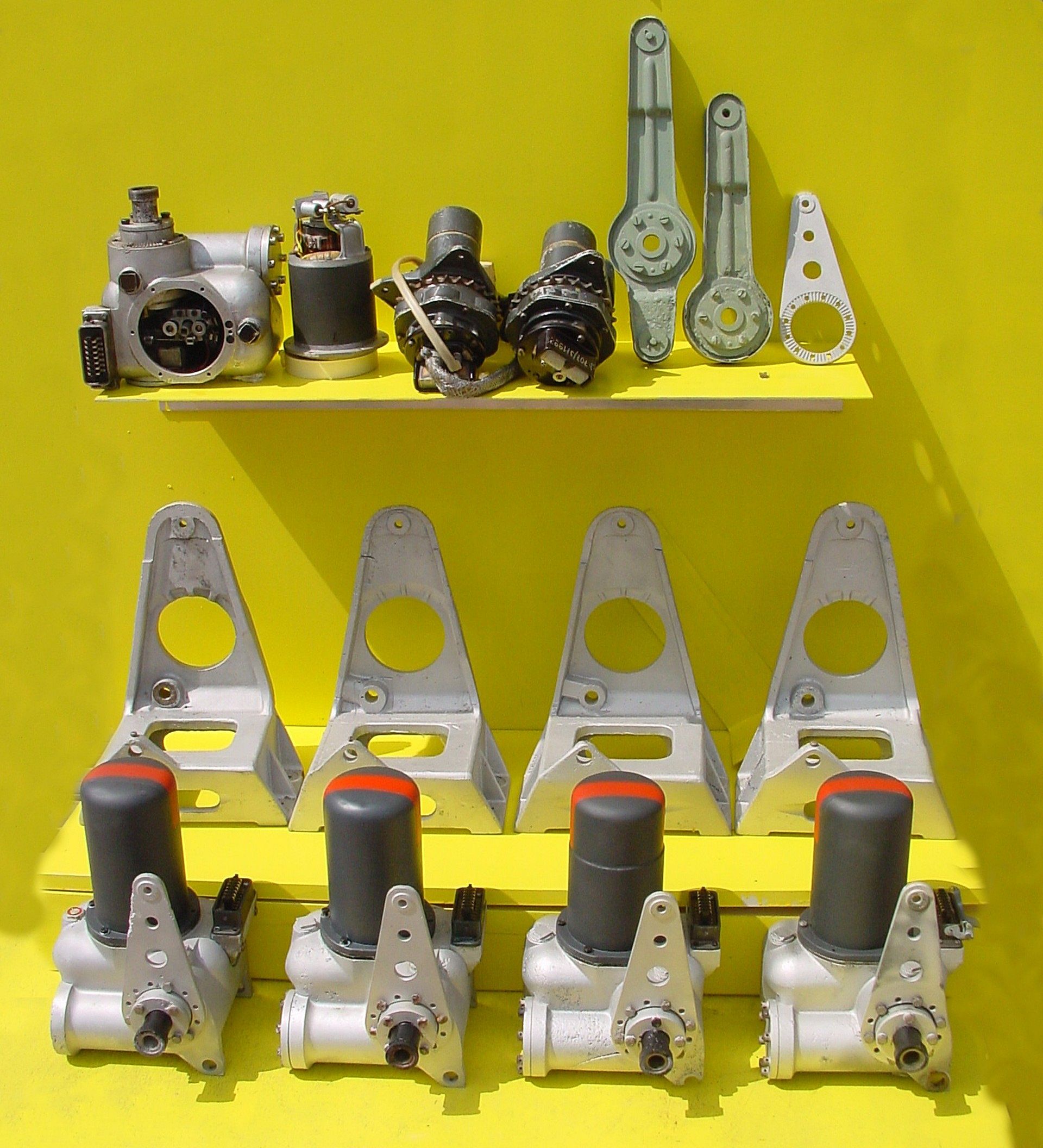
Photo shows a unique display at the Horst Beck Collection (HBC). Over many years Mr Horst Beck has painstakingly acquired and restored many A4-V2 missile parts – and in some cases, reassembled them into complete sub-assemblies. Shown here is part of the collection’s hydraulic servos and trim motor parts display. In the foreground we see four hydraulic servos, and behind them their A frame mounting ‘chairs’. The top shelf, from left to right, shows a servo with motor removed (and placed on its right). In the middle, two trim motors and chain sprocket gear-boxes for the aerodynamic trim surfaces on the trailing edge tips of fins 2 and 4. Next the pale green crank levers, the first longer one is for the hydraulic servo that controls the jet vanes and trimmers on fins 1 and 3. The shorter version minus the top horn, is used on the servos for fins 2 and 4. The last, silver coloured item,os a servo stabiliser (all the servos shown have one already fitted). Photo copyright: The Horst Beck Collection

Impact wreckage of electro-hydraulic jet vane servo
Impact wreckage of electro-hydraulic jet vane servo
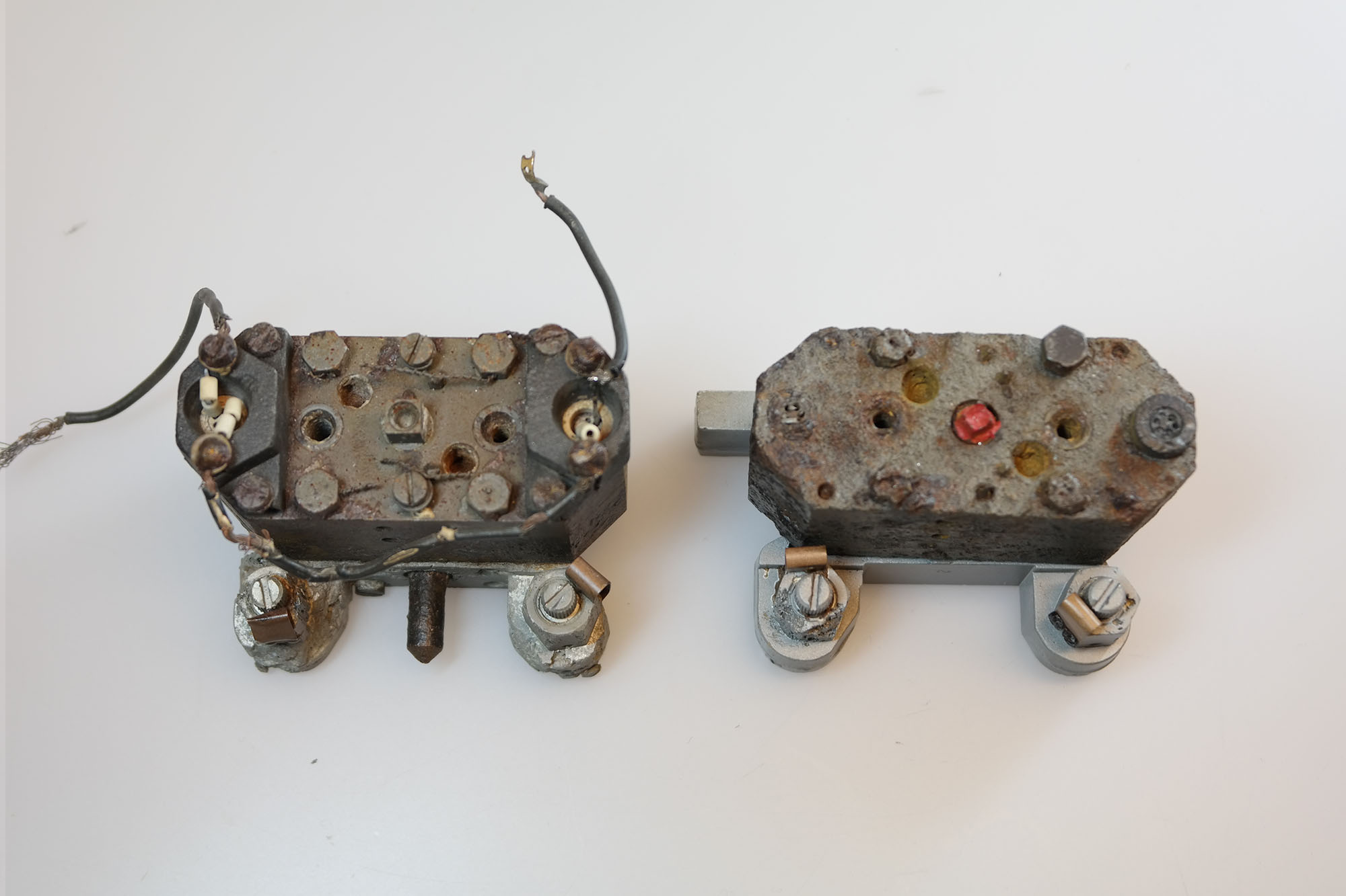
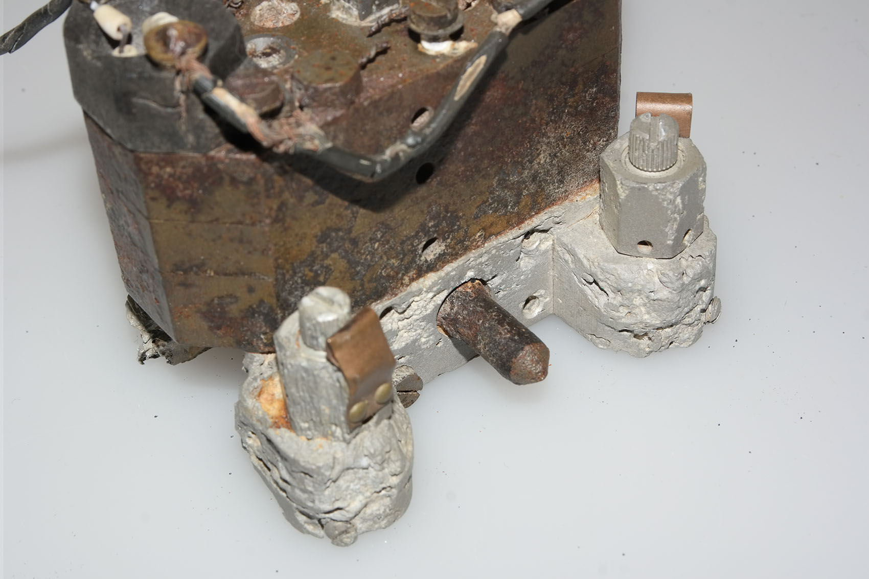
Wreckage of hydraulic servo from fin 2 or 4 of V2 missile that fell on a farm in Essex in March 1945. The motor has been removed and we can see details of the oil gear pump and valve control gear. The 3 position electromagnetic relay switch is visible at the 7 to 8 o’clock position within the open aperture. The push rod that connects the relay to the gear pump valves is also visible as a short brown coloured rod with a fine wire connector at each end, running in towards the gear-valves from the 9 o’clock position. The point that provides electrical current for the motor (which runs all the time and in one direction only) can be seen at the three o’clock position. The black housing has two sets of brass tongues that receive the matching brass spades mounted on the base of the motor for power input. The motor drive shaft has a female square socket coupling to connect the motor to the middle drive gear of the gear pump. A small portion of the square drive shaft of the central gear can just be seen in the photo – in the centre of the valve control block.

Hydraulic servo impact debris
Hydraulic servo impact debris
Hydraulic servo from fin 1 or 3 of the V2 missile, collected with other debris following a combat impact.
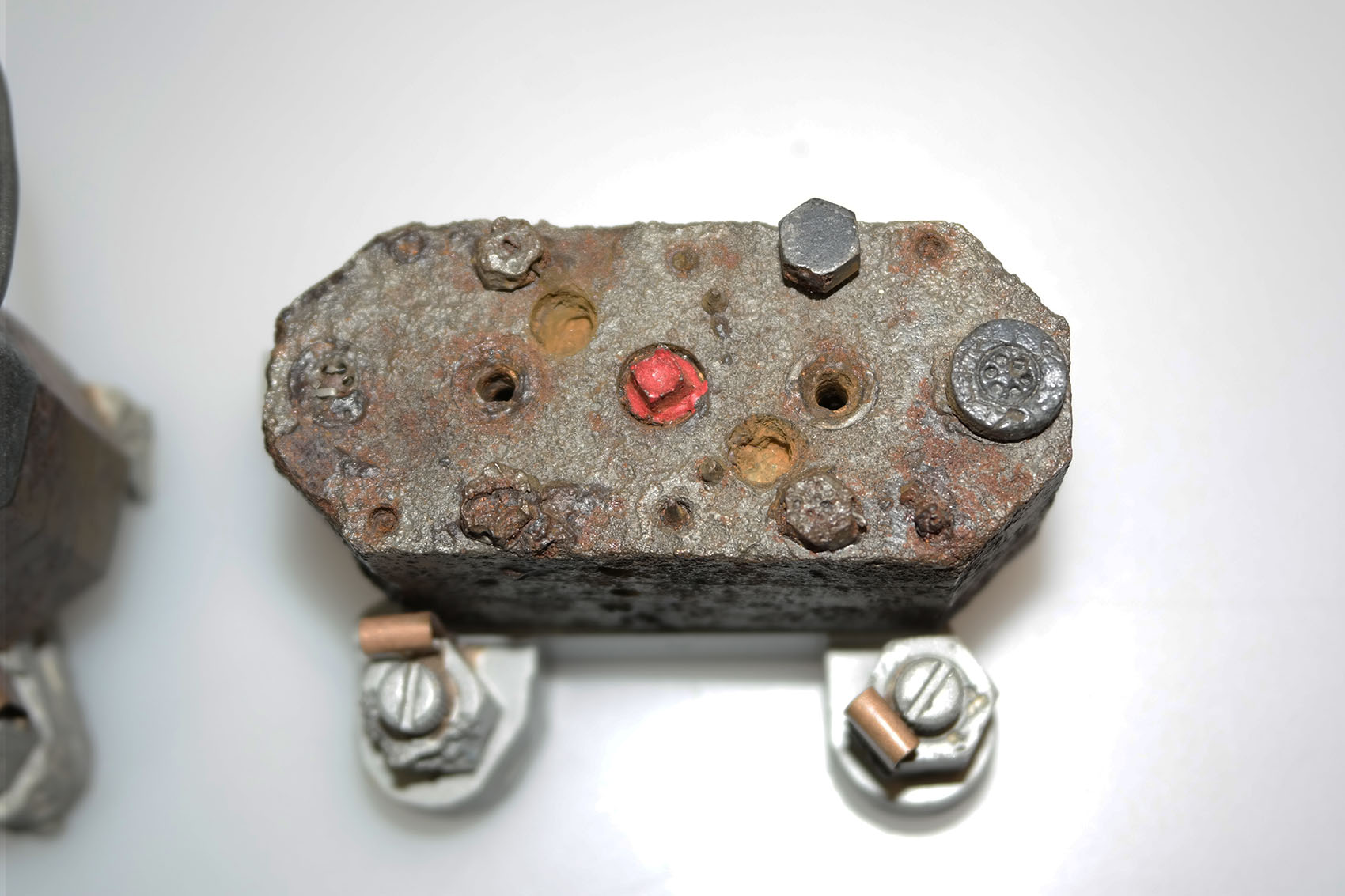
Hydraulic servo relics from Nordhausen
Hydraulic servo relics from Nordhausen
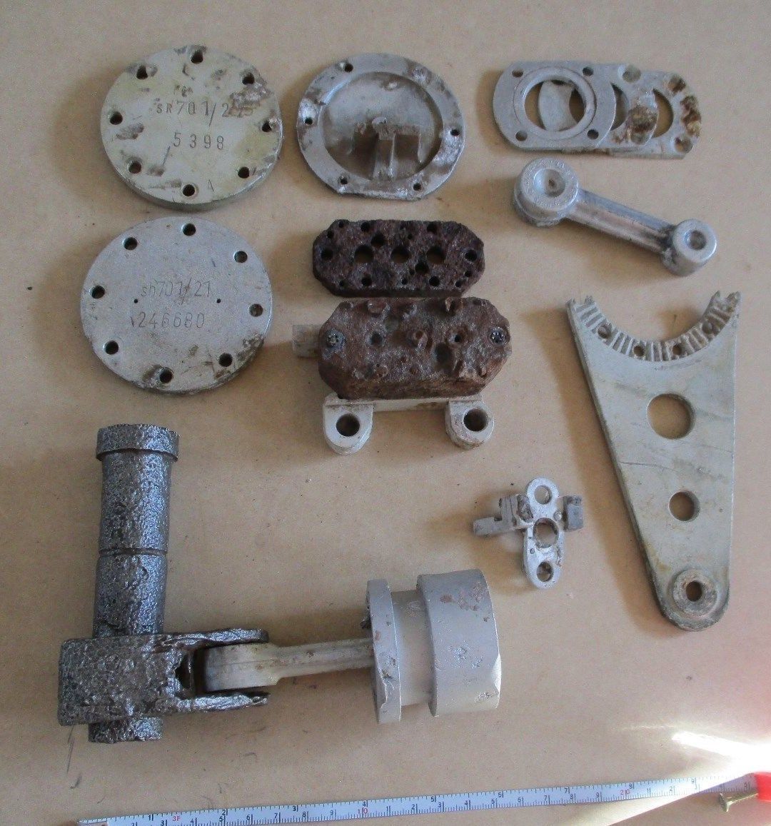
This collection of parts were all found in vicinity of the Nordhausen manufacturing facility. parts include servo crankcase caps -top left, electro-magnetic switch installation plate – middle top, crank bearing covers – top right, gear pump blocks with base – centre, and crank-shaft, piston rod, and hydraulic piston – btm left. The deep recess on the piston circumference is for a rubber seal and is an interesting variation in ring seal design (at least 4 variations of piston design were employed, with three designs flown on combat missiles). A valve tilt seat is visible a little to the right of the piston. A broken servo mount stabiliser is shown – middle right. The cast piston rod, top right, has not been drilled and milled – the part is ‘raw’ as supplied by the manufacturer before machining has been completed. Normally the manufacturer’s details are machined off the metalwork – but not in this rare case. The three letter code gfa is clearly visible on the part and stands for the firm of Otto Fuchs Metallwerke.
Fin and jet vane servo: Hydraulic gear pumps
Fin and jet vane servo: Hydraulic gear pumps
Two Askania (designed) hydraulic gear pumps – the examples shown here have two ceramic insulators with with Nichrome wire type heating elements. The heaters are located at each end of the pump on the long axis. The pump on the right still has its power supply wires attached and was easily repaired and restored to full function in our workshop.This type of pump (with heaters) seem to be rare among the debris of European combat impact sites but fairly common in debris collections emanating from research flights in Peenemünde and parts of Poland. An explanation maybe that the oil could be warmed up sufficiently simply by starting all four hydraulic gear pumps sooner in the pre-launch sequence. The only downside being that the already noisey missile would be making yet more noise in the risky period leading up to launch.
Hydraulic gear pump detail
Hydraulic gear pump detail
Close-up of Askania gear pump relic with oil heaters. This picture shows an unusual feature on the otherwise normal cast aluminium base of this gear pump. The knurled knob positioned between the oil flow balance adjusters has a purpose that is unknown to us. The two oil-flow balance adjuster valves visible in the picture have slot head adjuster screws and you can also see the knurled circumference on each screw. This parallel knurling is engaged by a crease formed in the facing surface of the copper spring strips. The function of these strips is to create tactile feedback that the technician making the adjustment can feel in the handle of the screwdriver. This was done because the gear pump needed to be adjusted in a dark and narrowly confined space.
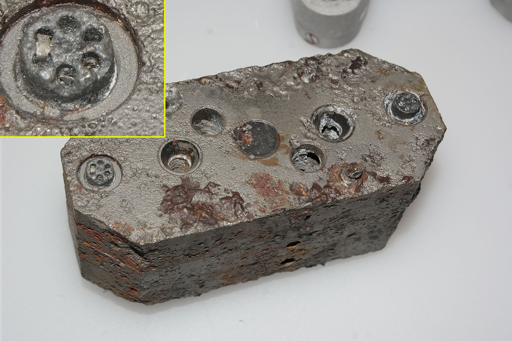
Gear pump showing flow adjusters and ceramic heater elements
Gear pump showing flow adjusters and ceramic heater elements
Gear pump showing flow adjusters (two slot head screws nearest bottom of picture) and ceramic heater elements situated at each end of the block. The square drive shaft coupler (corroded but still identifiable) has been highlighted in red paint. The open holes either side are the main control valve guides. The copper spring strips visible on each oil flow adjuster provide locking and tactile feed-back for the adjusting process. This relic was recovered from Usedom island.
Gear pump detail showing ceramic insulator with nichrome element
Gear pump detail showing ceramic insulator with nichrome element
Hydraulic gear pump with close up detail showing ceramic heater element insulators with flat, possibly nichome, metal strip element threaded through them. This oil heating system was designed to maintain a specific viscosity of the oil regardless of environmental temperature, to better maintain oil flow rates and thus pump efficiency. The heating system is found only rarely on surviving relics.
A4-V2 graphite jet vane
A4-V2 graphite jet vane
Photo shows a flown graphite jet vane complete with mounting plate and fasteners as well as pre-flight centre index tip. V2 relic from the Horst Beck Collection (HBC). Photo copyright: The Horst Beck Collection
Graphite jet vane replica
Graphite jet vane replica
V2 missile graphite jet vane defector replica made for V2 Rocket History.
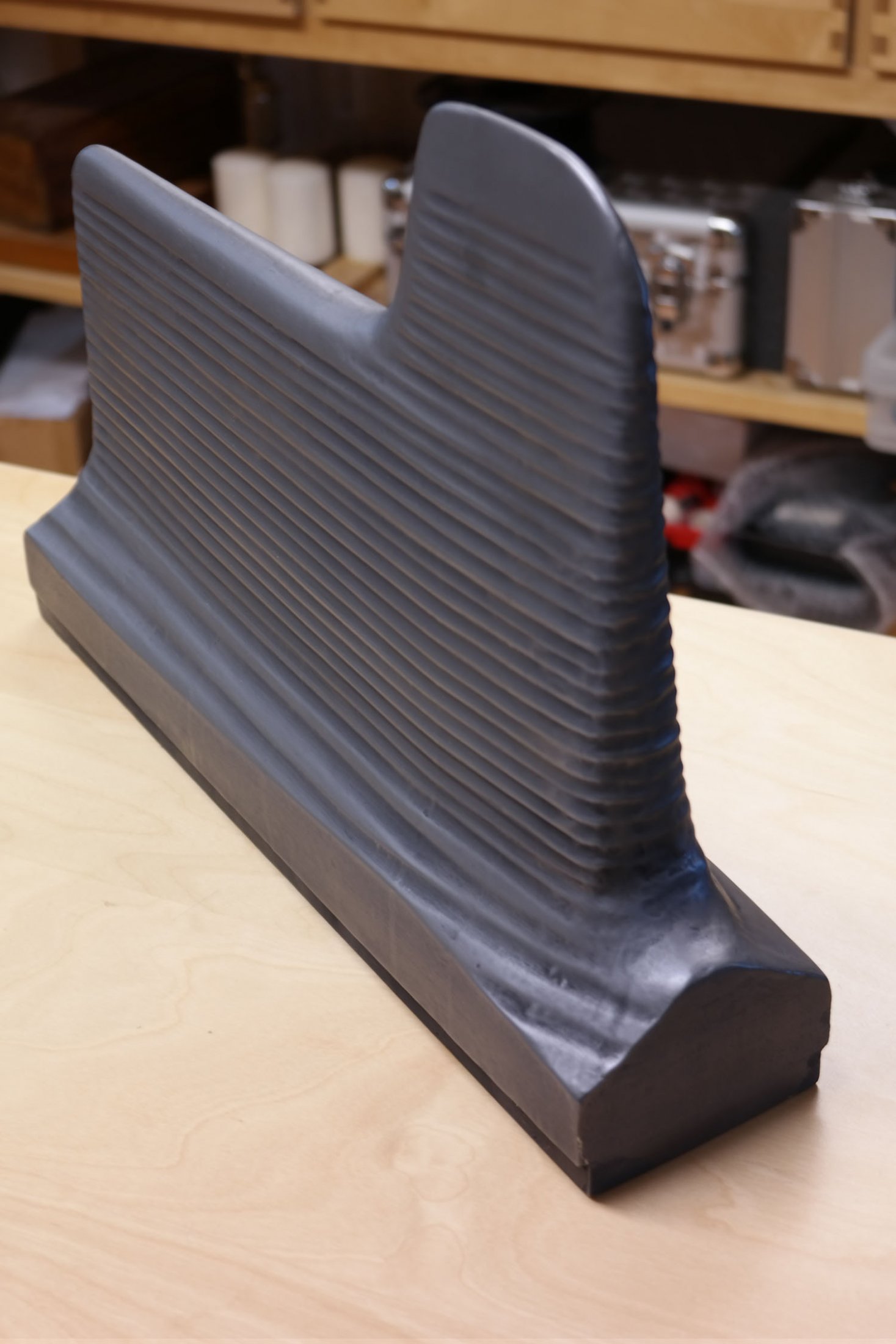
Graphite vane rocket jet deflector replica
Graphite vane rocket jet deflector replica
V2 missile graphite jet vane defector replica made for V2 Rocket History. This accurate replica shows the distinctive pantograph mill tool ‘witness’ marks well.

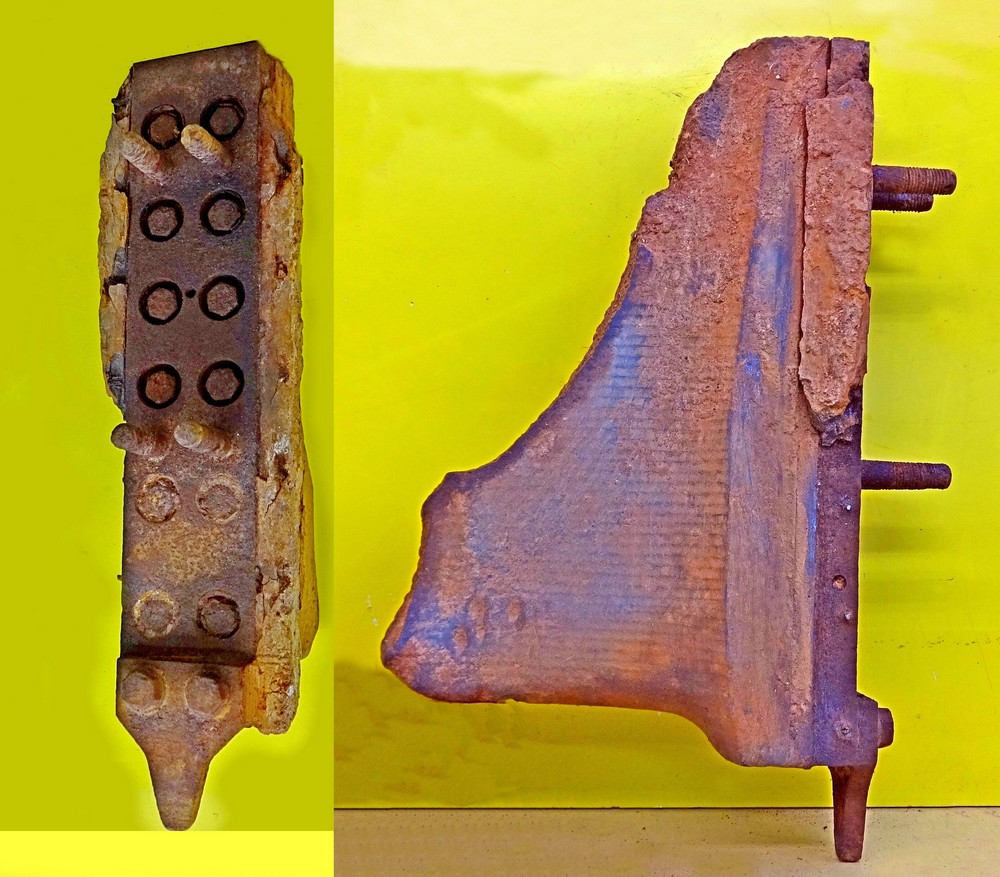
Restored graphite vane thrust ring support housings. ©THBC
Restored graphite vane thrust ring support housings. ©THBC
Photo shows four restored graphite jet vane support blocks and bearing housings. The round plates we can see here act as heat sinks and allow heat to radiate away from the support block and bearing to help prevent expansion due to relatively rapid and uneven temperature distribution accumulation. The graphite vanes were quite brittle and cracking caused by rapid and uneven expansion could cause the vane to disintegrate. The area around the graphite vanes was exposed to the accumulation of heat not merely as a result of duration of the motor burn time but temperature was also increased at higher rates as the jet plume expanded with the decreasing atmospheric pressure as the missile gained altitude. This excellent restoration is the work of Horst Beck. Photo copyright: The Horst Beck Collection
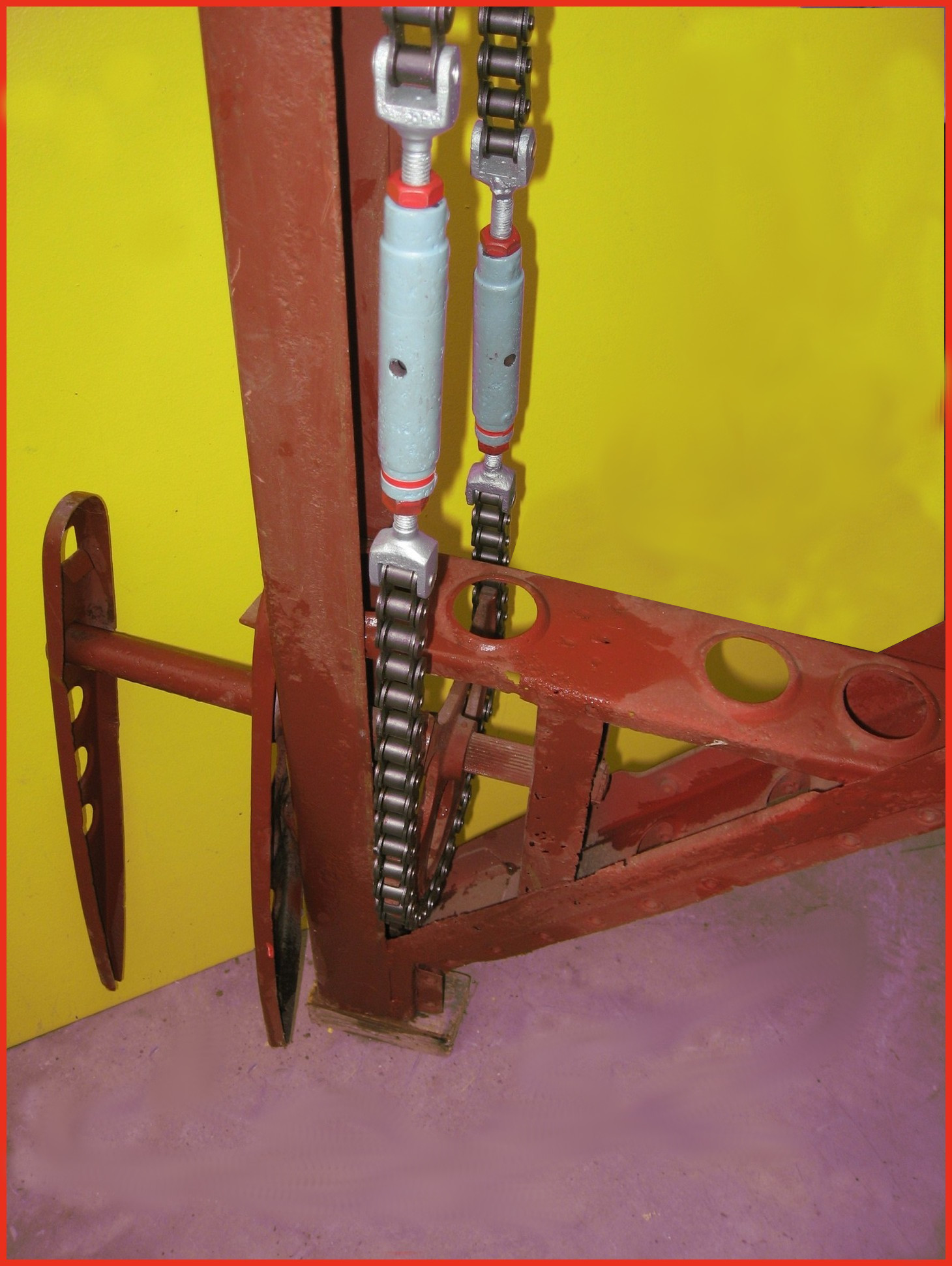
A4-V2 air rudder detail. ©THBC
A4-V2 air rudder detail. ©THBC
Photo shows restored air-rudder and fin detail. The grey painted barrel-strainers are both adjusted independently to reduce slack in the drive chain and avoid introducing a deflection bias in the air rudder. The 1.9kg counterbalance weight normally located at the top of the trim fin (or air rudder) is missing in this presentation. This excellent restoration is the work of Horst Beck. Photo copyright: The Horst Beck Collection
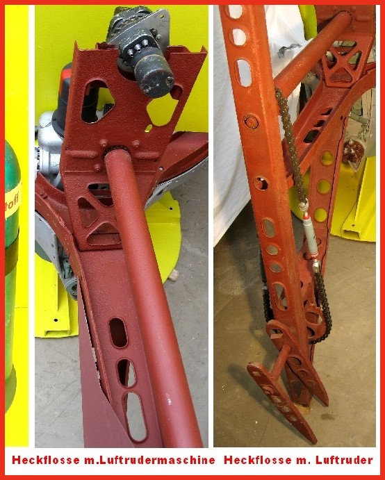
Detail of fin 2 or 4 showing trim motor and drive chain
Detail of fin 2 or 4 showing trim motor and drive chain
Photo shows partially restored air-rudder and fin detail. The image on the left shows the relationship of the trim motor to the air rudder drive shaft on fins 2 and 4. A chain similar in gauge to the type used on a push-bike and yet, at the other end of the shaft, the chain transmitting the torque of the trim motor to the air-rudder drive sprocket has a heavy gauge chain similar to that found on a 1000CC motor-cycle! This excellent restoration is the work of Horst Beck. Photo copyright: The Horst Beck Collection

Ernst Steinhoff
Ernst Steinhoff
Ernst Steinhoff, chief of the BSM workshop (Guidance and Control) in the development works Peenemunde.
Equipment bays
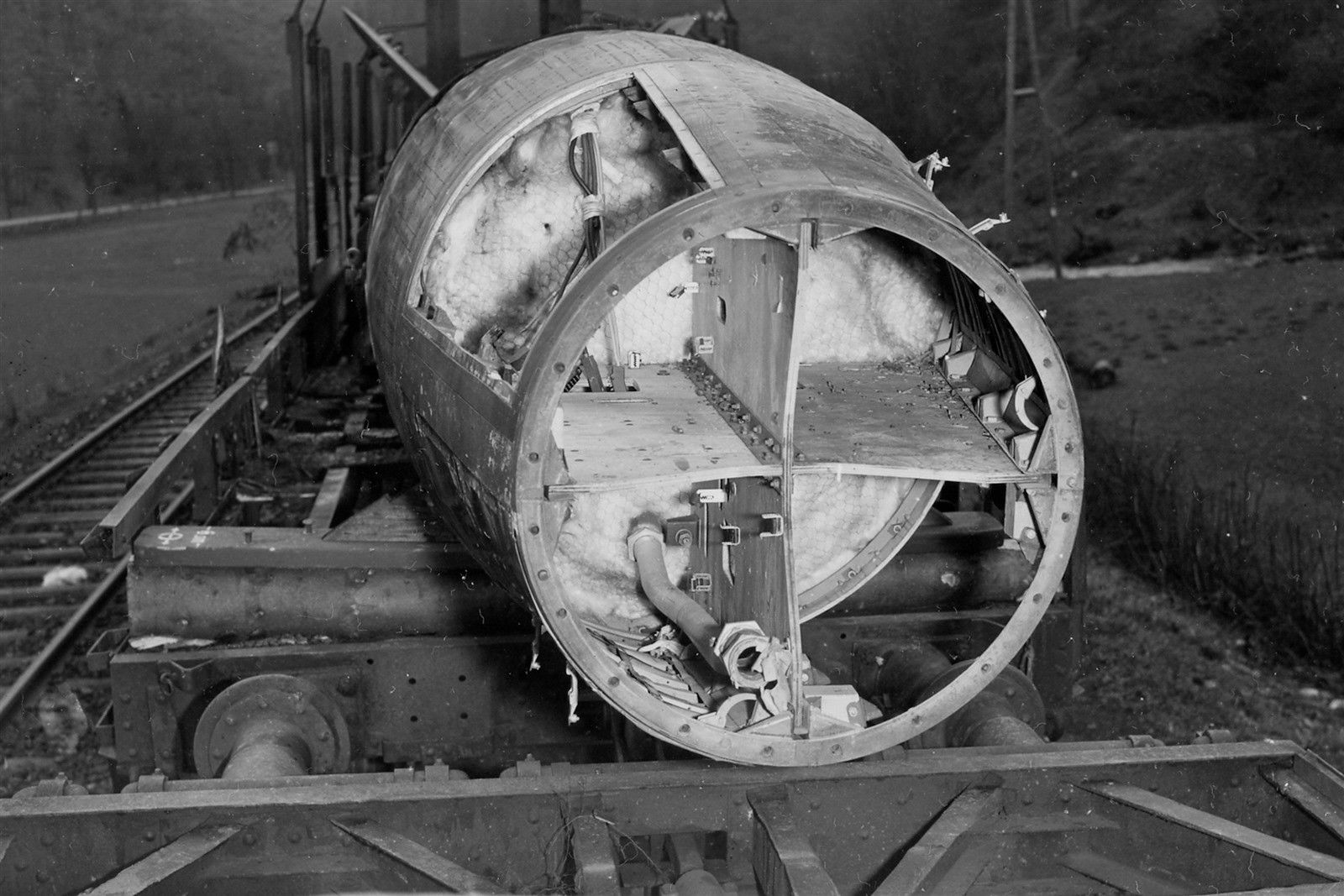
V2 missile on rail wagon showing control bays
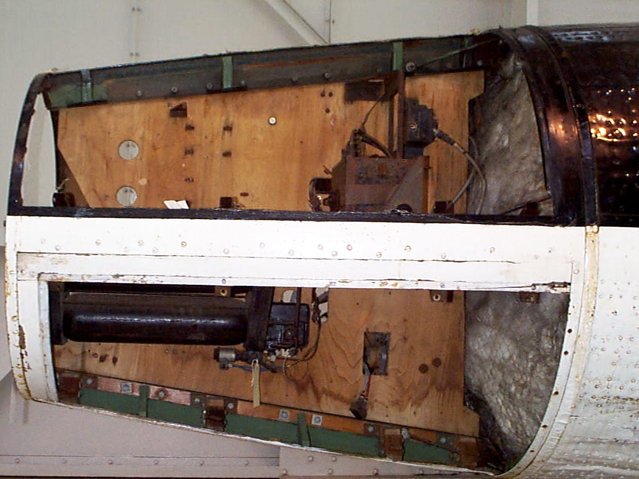
V2 missile on rail wagon showing control bays
Incomplete V2 missile on rail transporter. All 4 control compartments are well shown. The fuel tank connection pipe can be seen but not much else. All of the control equipment has been removed. Plainly visible is the chicken wire holding the fiber wool tank insulation in place. Today this would be called ‘Galvanised hexagonal network restraining matrix, and be supplied by a blue chip Aerospace company for $800 per square inch. In the 1940s, it was just chicken wire at a 2 dollars for a 100 ft roll.
| Album | Equipment bays |
Control compartments 1 & 4
Control compartments 1 & 4
Control compartments 1 (upper) & 4 (lower) Image copyright Imperial War Museum
| Album | Equipment bays |
| Category | Missile guidence |
Control compartment 3
Control compartment 3
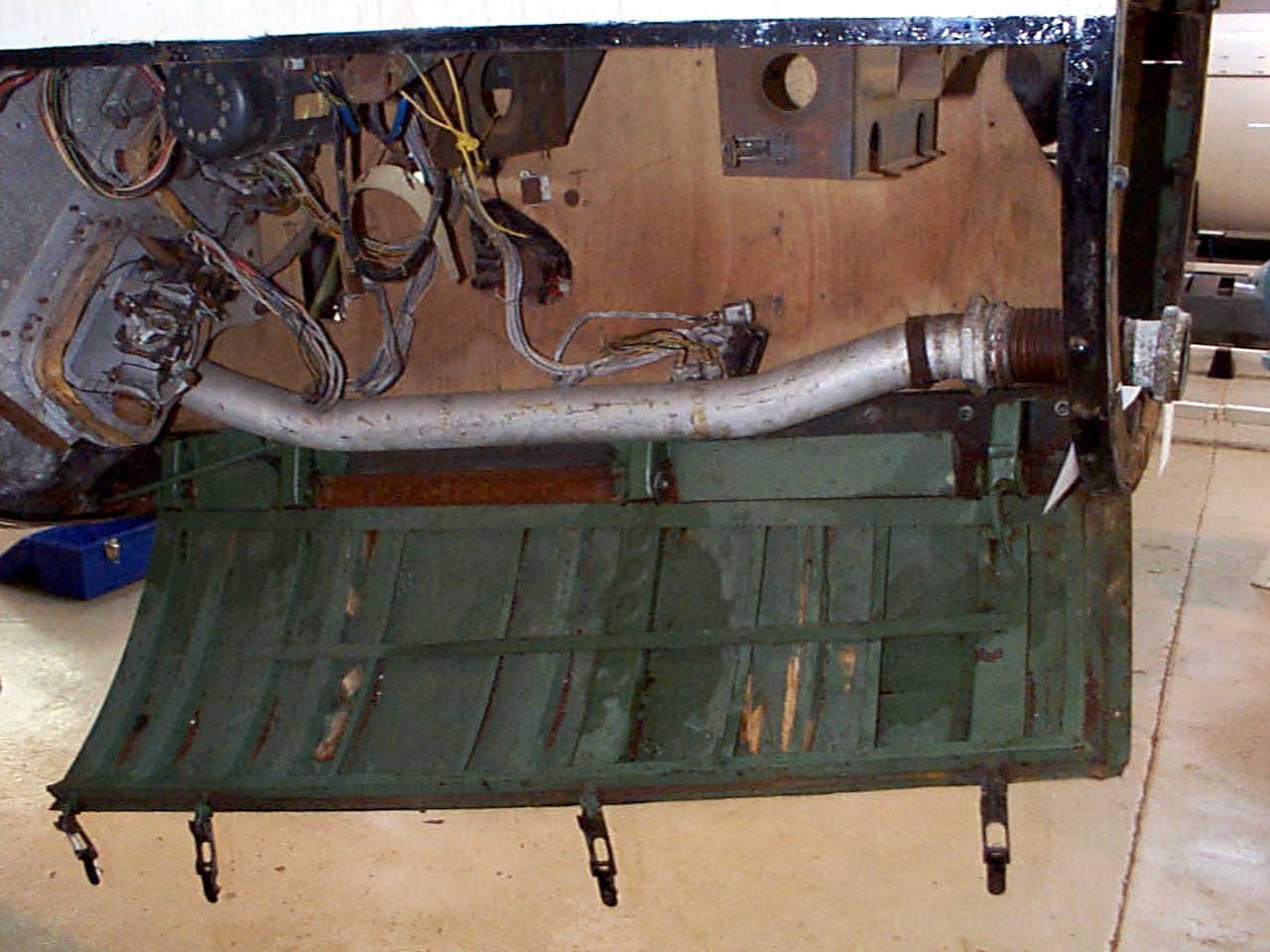
Control compartments 3 showing gyro mounting platform with two gyros and DC motor driven 3 phase AC voltage generator. The alcohol tank pressurisation pipe is also shown running through the equipment bay (large silver coloured pipe). Image copyright Imperial War Museum
| Album | Equipment bays |
| Category | Guidence |
Control compartment 1
Control compartment 1
Control compartments 1. Image copyright Imperial War Museum
| Album | Equipment bays |
| Category | Electrical connection |
Control compartment 2
Control compartment 2
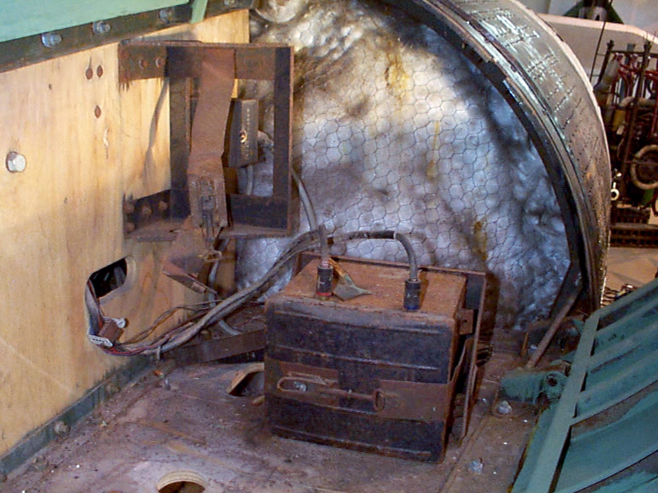
Control compartment 2 showing plywood separation panels, Oemig umformer (DC to 3 phase AC voltage generator), and voltage frequency control box. Towards the rear the ground connection plugs can just be seen and the mechanism of the cable release trap door (see cat flap!). Image copyright Imperial War Museum
| Album | Equipment bays |
| Category | Electrical connection |
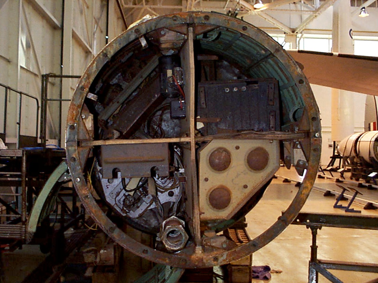
Control compartments – all 4 top view
Control compartments – all 4 top view
Control compartment 1 top right, 2 top left, 3 bottom left, and 4 bottom right. The fuel tank pressurisation pipe upper connection point is well shown at about 6 o’clock (compartment 3) and just above and to the right the upper plate of the air (N) tank rack (tan colour). Image copyright Imperial War Museum
showing plywood separation panels, Oemig umform
| Album | Equipment bays |
Missile guidance equipment
Images of guidance and missile control equiment


Missile guidance equipment
Images of guidance and missile control equiment
LEV-3 Horizont and Vertikant gyroscope system 1940
category:Missile guidence, Sub-assemblies


Description
LEV-3 V2 missile gyroscope system with mounting plate. The third component of this system, the Muller gyroscopic accelerometer, is missing – the 2x mounting points can be seen on the right-hand side of the mounting plate.
Location
