

Archives: Gmedia Albums


The Enigmas

Fuel injector flow test results
Fuel injector flow test results
The chart shows water delivery in litres per minute per injector
| Album | Testing fuel injectors |
| Categories | Combustion, Propellant flow |
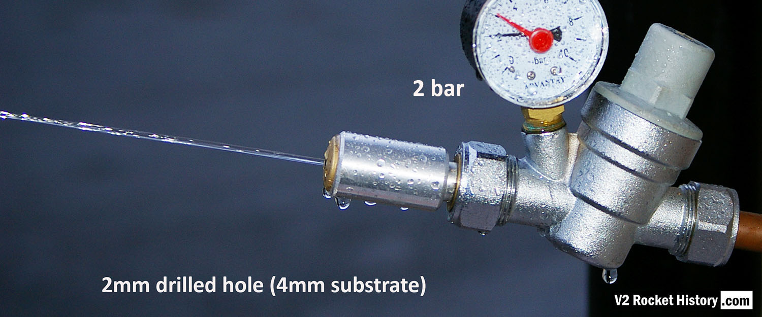
Jet from 2mm drilled fuel feed hole
Jet from 2mm drilled fuel feed hole
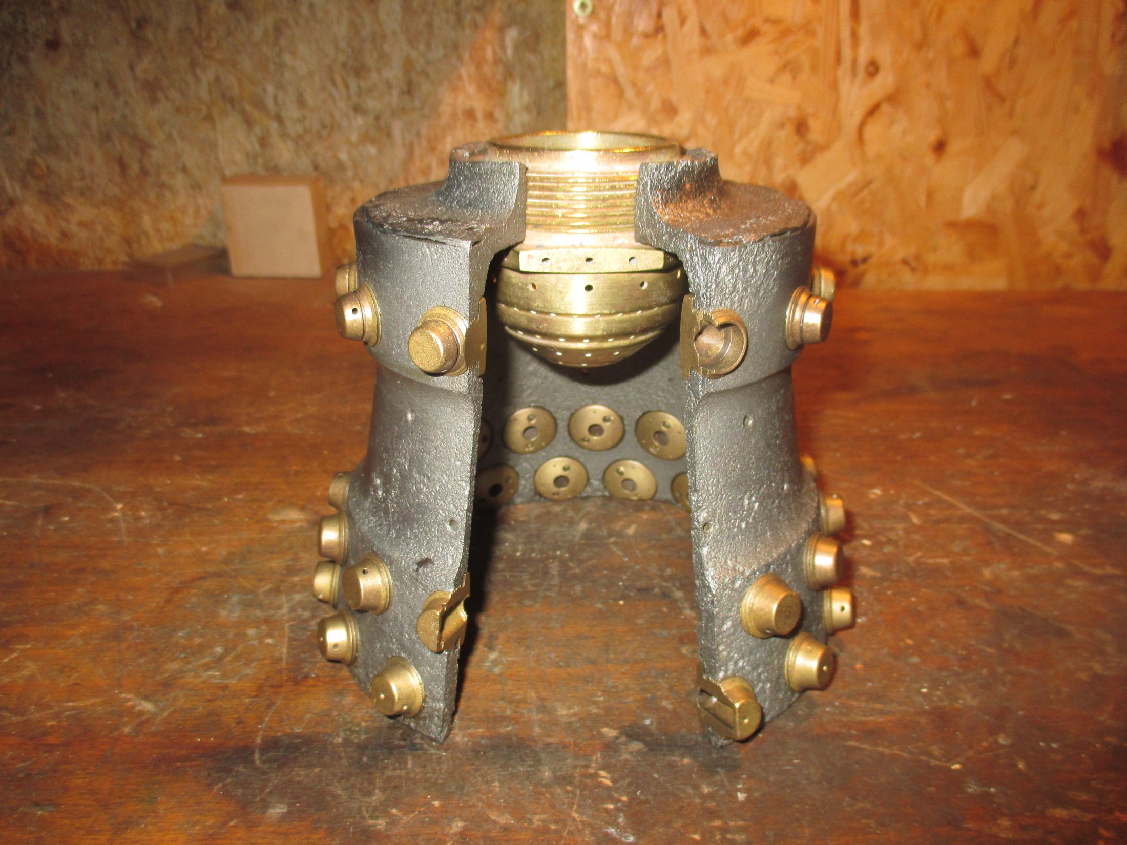
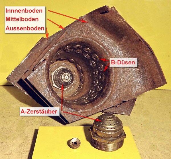
Each burner cup of the V2 rocket engine injector system has forty-four brass inserts, but each cup also has twenty-four 2mm diameter plain holes, 30 deg apart, drilled into the cup’s central wall. To mimic this for testing purposes, we created a brass insert that has a base with just a 2mm central hole. The base is sized to be consistent with the 4 to 5mm cup wall. V2RH image

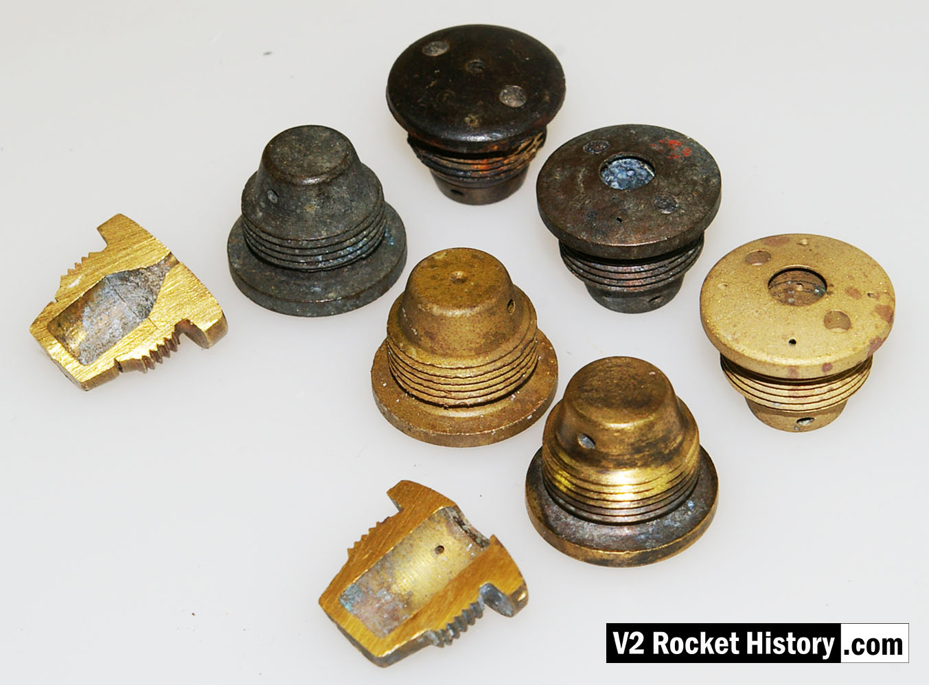
V2 Fuel Injector insert test stock
V2 Fuel Injector insert test stock
V2 rocket engine fuel injector inserts – a part of our collection used for the water tests with various types shown. The tool shown is a pin-wrench used to fit the inserts into the test apparatus. V2RH collection image
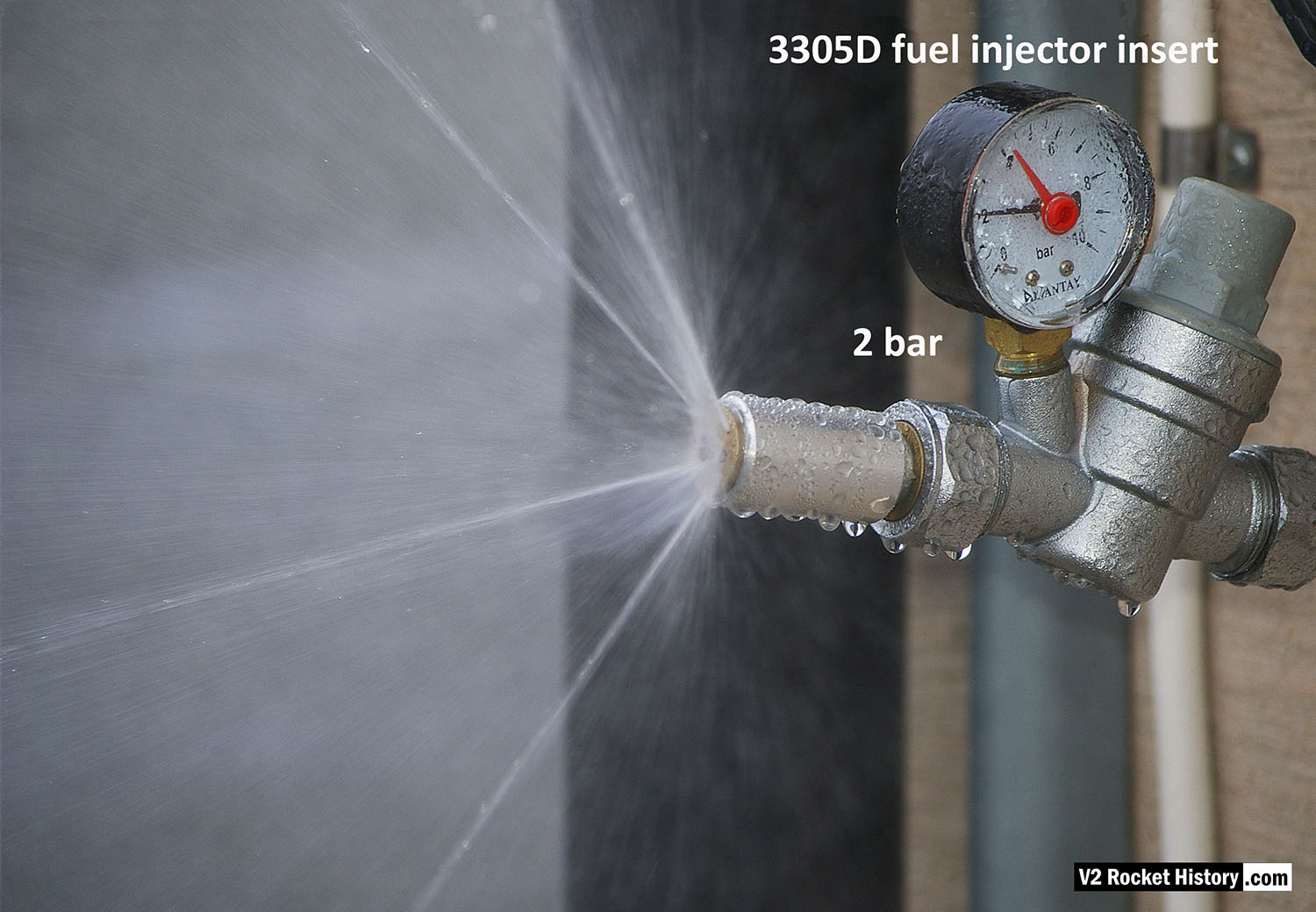
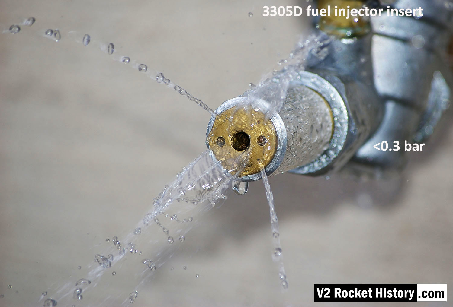
3305D Water test nebular pattern
3305D Water test nebular pattern
3305D fuel injector insert showing swirl cone nebular, and 4 steady steams emanating from cooling pores.
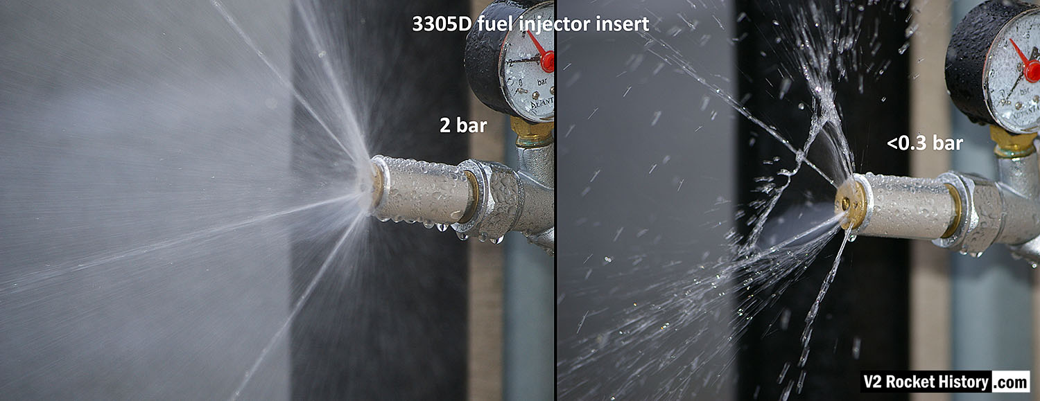
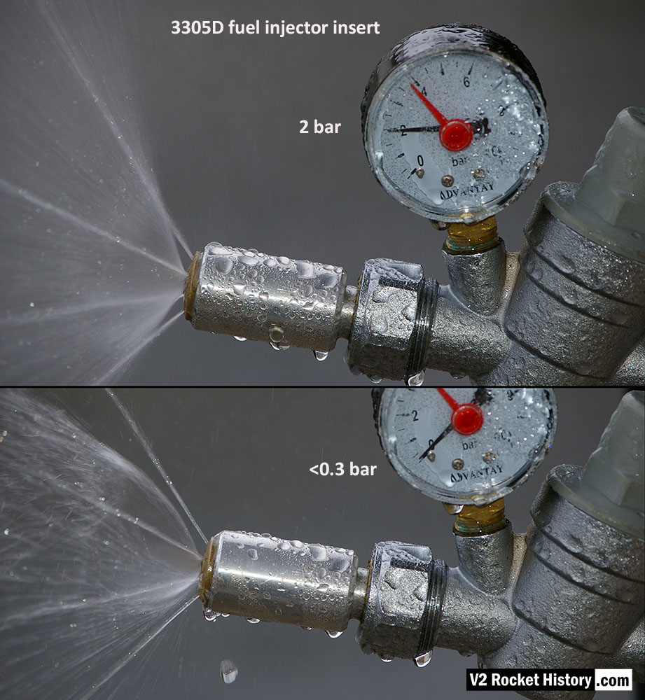
3305D Water Test Comparison 2
3305D Water Test Comparison 2
3305D fuel njector insert showing comparison nebular and jet stream pattern with high and low pressure. Left image shows correct hollow cone-shaped aerosol effect from central 6mm orifice, that is also creating a fine mist around and within the cone, and 4 steady steams emanating from cooling pores. Right image shows the effect of reduced pressure: a dropping poorly formed cone, composed of larger slower moving droplets, and a tendency for the thicker spray to combine and cause ‘dribbeling’ with much fluid failing to clear the injector face.
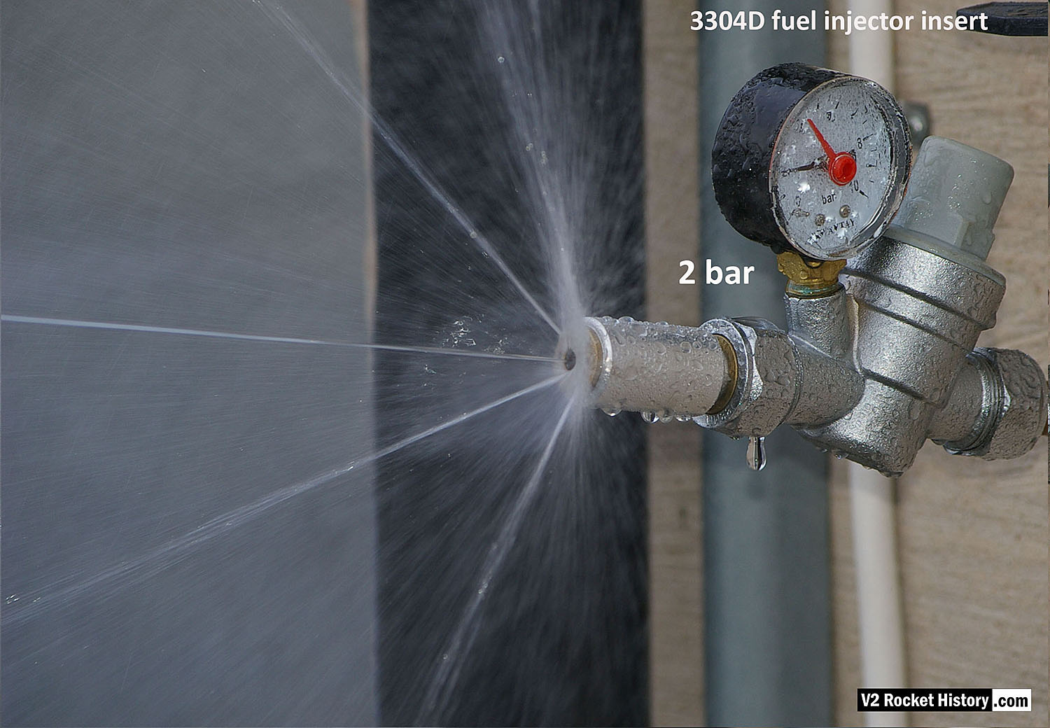
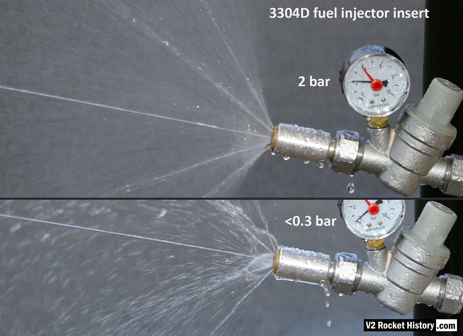
3304D Water test nebular pattern showing central jet
3304D Water test nebular pattern showing central jet
3304D higher volume fuel injector insert (with three inlet apertures: 2 swirl, 1 jet) showing swirl cone nebular, steady central jet, and 4 steady steams emanating from cooling pores.

Fuel Injector insert showing aperture details
Fuel Injector insert showing aperture details
Standard fuel injector inserts for production series 18-pot injector head. Insert 1 (3304D/3305D) shows four thin wires demonstrating the angles of all four ‘cooling’ pores. Insert 2 (3305D/2131E) has two 1.3mm twist drill showing the edge bores for the gyroscopic swirl inlets. Insert 3 (3305D) shows another view of the cooling pore angle and origin. V2RH image

V2 Fuel Injector 2131E
V2 Fuel Injector 2131E
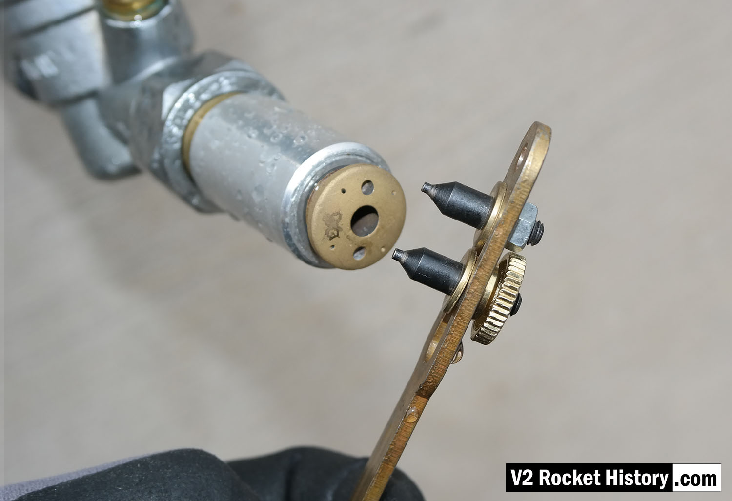
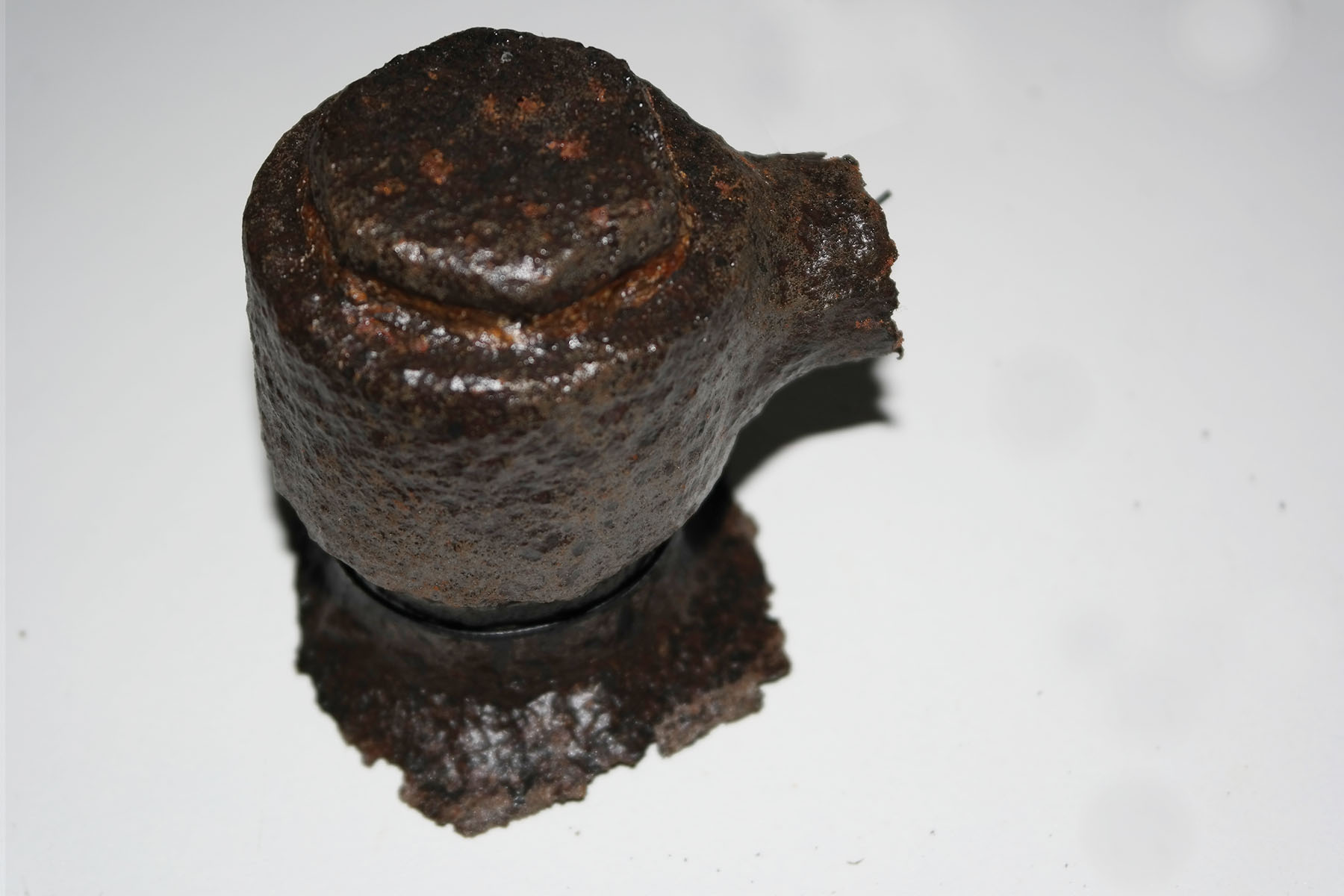
V2 Fuel Injector insert: part code 2131E from injector pot echelon A (nearest to LOX spray head). The push-together two part construction of the insert is shown here. The two parts were pushed together in a specially shaped tool set that compressed the thin skirt on the female part into a recess cut into the male part. The failure test for this component required that the mated parts resist a separating force of 300kg. The two part design was dictated by the small size of the 2mm exit orifice and the funnel shaped introduction to the exit orifice. In the case of the other three standard inserts, the large 6mm exit orifice allowed a sub 6mm milling cutter, with a thin support shaft and a top chamfer, to be used in such a way that the area below the exit orifice could be undercut to create an injector cavity with a diameter larger than the 6mm entry point.
Swirl nozzle insert set 2
Swirl nozzle insert set 2
Fuel injector inserts for production series 18-pot injector head showing general shape and thread position. For further details see associated image. The lowermost insert have been halved to reveal the cavity shape, orifice edge, inlet and cooling apertures. V2RH image

V2 fuel injector Insert test rig
V2 fuel injector Insert test rig
Single nozzle insert test rig used by V2 Rocket History to test spray shape and volume at supply pressures consistent with fuel pressures specified for the injector head of summer 1944. The test system features an adjustable pressure regulator and fluid pressure gauge. For test purposes the device was simply connected to a relatively high pressure mains water supply. And although water does not have the same viscosity of the 75% Ethenol to 25% water mix of the V2’s fuel it was considered close enough by the German technicians, who regularly used plain water as a substitute when testing issues related to furl flow rather than combustion. A 2131E fuel injector insert is shown installed in the holder at the front of the rig, but as the thread was the same on all inserts the nozzle can be changed for other models easily with aid of a pin spanner. See video for a demonstration of this simple test system.

Test Rig With E Type Insert
Test Rig With E Type Insert
Single nozzle insert test rig used by V2 Rocket History to test spray shape and volume at fluid supply pressures consistent with fuel pressures specified for the injector head of summer 1944. A 2131E fuel injector insert is installed in the holder at the front of the test rig, but as the thread was the same on all inserts the nozzle can be changed for other models easily with aid of a pin spanner. See video for a demonstration of this simple test system.
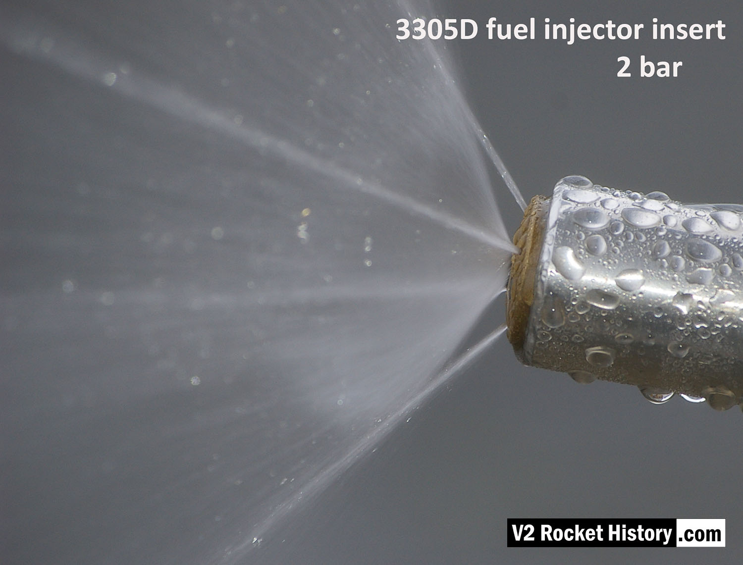
3305D Water Test Pattern
3305D Water Test Pattern
3305D injector insert showing larger low-velocity droplets and ‘dribbly’ performance due to insufficient pressure. The cone shaped aerosol is not functioning. Broken streams can be seem emanating from the four cooling pores.
3305D Water Test Comparison
3305D Water Test Comparison
3305D injector insert showing comparison nebular and jet stream pattern with high and low pressure. Top image shows correct hollow cone-shaped aerosol effect, from central 6mm orifice, that is also creating a fine mist around and within the cone, and steady steams emanating from cooling pores. Bottom image shows the effect of reduced pressure: a dropping poorly formed cone, composed of larger slower moving droplets, and a tendency for the thicker spray to combine and cause ‘dribbeling’ with much fluid failing to clear the injector face – unlike the image above, where the injector face is clear of drips.
3305D Close-up of nebular cone & cooling jets
3305D Close-up of nebular cone & cooling jets
Image shows a correctly formed nebular cone attended by a fine mist. the four injector cooling jets are well shown, and although fluid beading can be seen on the face of the injector, there is insufficient liquid to cause dripping.
Injector test rig showing pin wrench to fit inserts
Injector test rig showing pin wrench to fit inserts
Single fuel injector water test rig showing a 3305D bress insert about to be tightened home using a pin-wrench. V2RH image
Fuel injector 3304D water test comparison
Fuel injector 3304D water test comparison
3304D higher volume injector insert (with central jet) showing comparison nebular and jet stream pattern with high and low pressure. Top image shows correct hollow cone-shaped aerosol effect from central 6mm orifice, that is also creating a fine mist around and within the cone, and strong single central (non-swirl) jet can be seen as well as 4 steady steams emanating from cooling pores. Bottom image shows the effect of reduced pressure: a dropping poorly formed cone, composed of larger slower moving droplets, and a tendency for the thicker spray to combine and cause ‘dribbeling’ with much fluid failing to clear the injector face. The appearance of central jet however seem largely unchanged.
F1: Fertigungshalle Eins

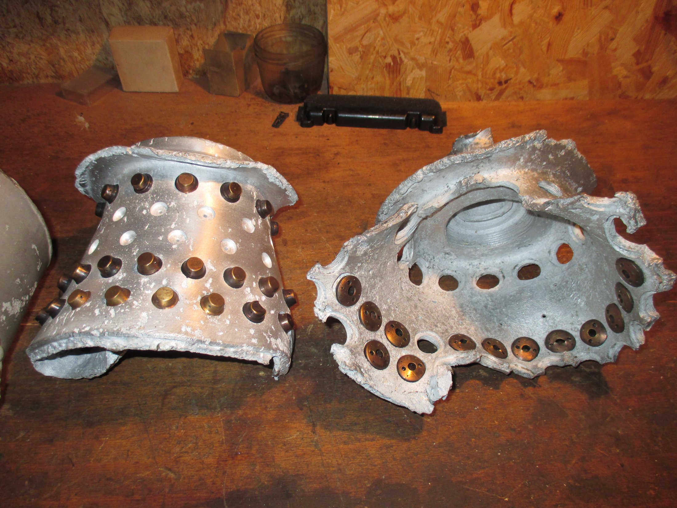
25-Ton aluminium injector pot from 1940/41
25-Ton aluminium injector pot from 1940/41
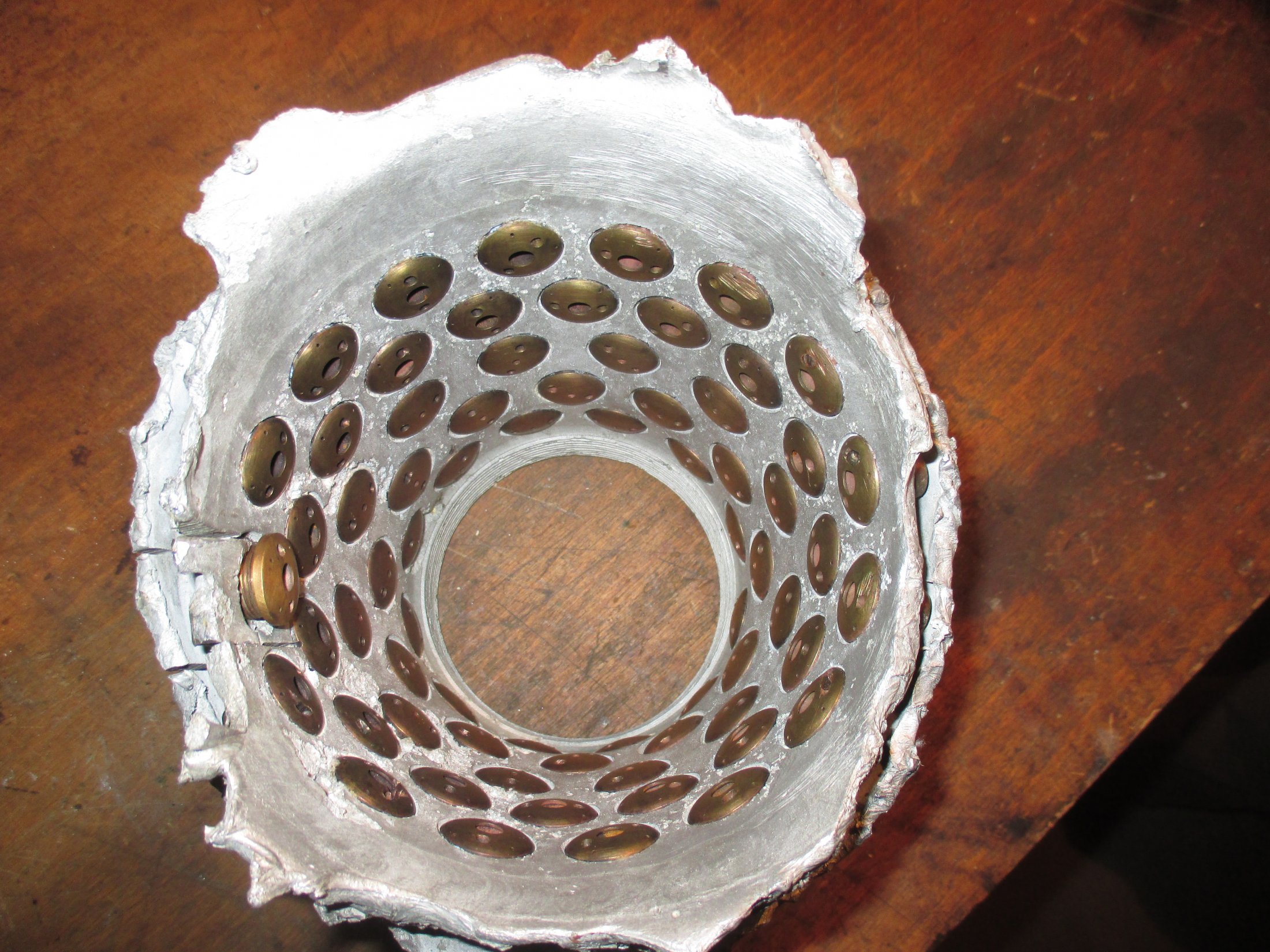
Relic of prototype A4 25-ton 1940/41 aluminium injector head basket (or pre-chamber) showing 68 copper alloy inserts in 5 rows. The standard configuration would later become 44 inserts in 3 rows 25 2mm diameter drilled holes in two rows situated at row 3 and 4 (counting from nearest the camera). Photo courtesy Host Beck Collection
Collection Parts of the ‘Standard’ series A head
Collection Parts of the ‘Standard’ series A head
Parts of the ‘Standard’ series A aluminium head from 1941. The brass injector insert type and position pattern on the relics seem to be of the standard type but the pattern is non-standard in that higher volume injectors with three inlet apertures (two centrifugal and one central) have been place nearest the LOX
injector. Photo courtesy Horst Beck
Relics of the ‘Standard’ series A aluminium head c. 1941
Relics of the ‘Standard’ series A aluminium head c. 1941
Relics of the A4 25-ton 1941 aluminium injector head. See other photos in this series for more detail. Photo courtesy Horst Beck Collection
Part of the ‘Standard’ series A aluminium head from 1941/42
Part of the ‘Standard’ series A aluminium head from 1941/42
Part of the ‘Standard’ series A aluminium head from 1941 to early 1942. Showing the position of standard type LOX injector. The brass fuel injector inserts type and position pattern on the relic seem to be of the standard type with the row of 3 inlet aperture type inserts positioned furthest from the LOX injector. Photo courtesy Horst Beck Collection
Aluminium Injector basket with 68 inserts from 1940/41
Aluminium Injector basket with 68 inserts from 1940/41
Relic of A4 25-ton 1940/41 aluminium injector head basket (or pre-chamber) showing 68 copper alloy inserts in 5 rows. The standard configuration would later become 44 inserts in 3 rows 25 2mm diameter drilled holes in two rows situated at row 3 and 4 (counting from nearest the camera). Photo courtesy Host Beck Collection
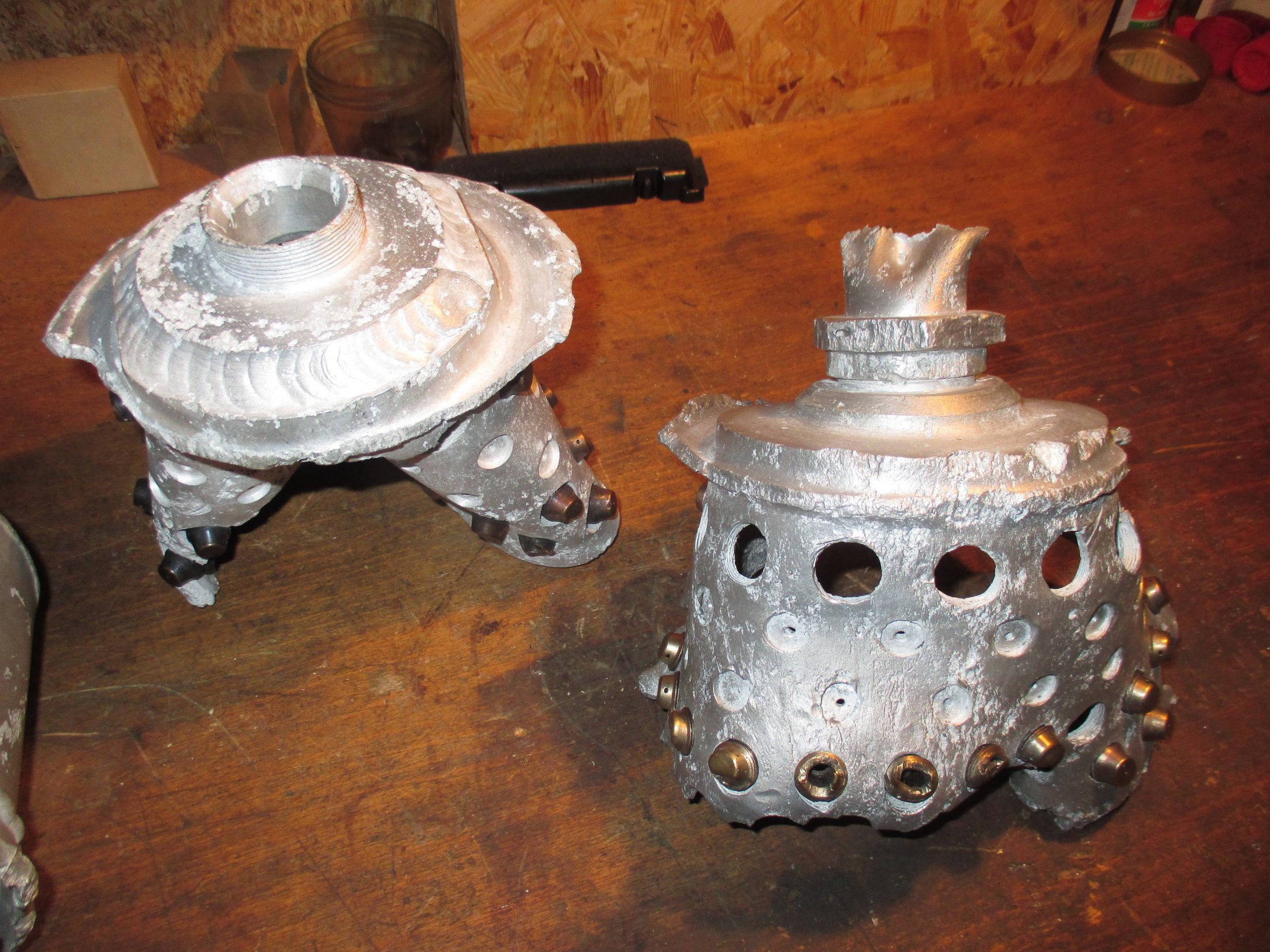
Part of 25-Ton aluminium injector head
Part of 25-Ton aluminium injector head
25-Ton aluminium injector head showing mpe armament code for the Heimat-Artillerie-Park 11 (HAP11) Karlshagen Werk Nord.


Flown V2 combustion injector head relic from 1945
Flown V2 combustion injector head relic from 1945
Injector head relic from February 1945 showing injector insert type and pattern. Photo www.v2rockethistory.com


Flown V2 thrust chamber relic – 1945
Flown V2 thrust chamber relic – 1945
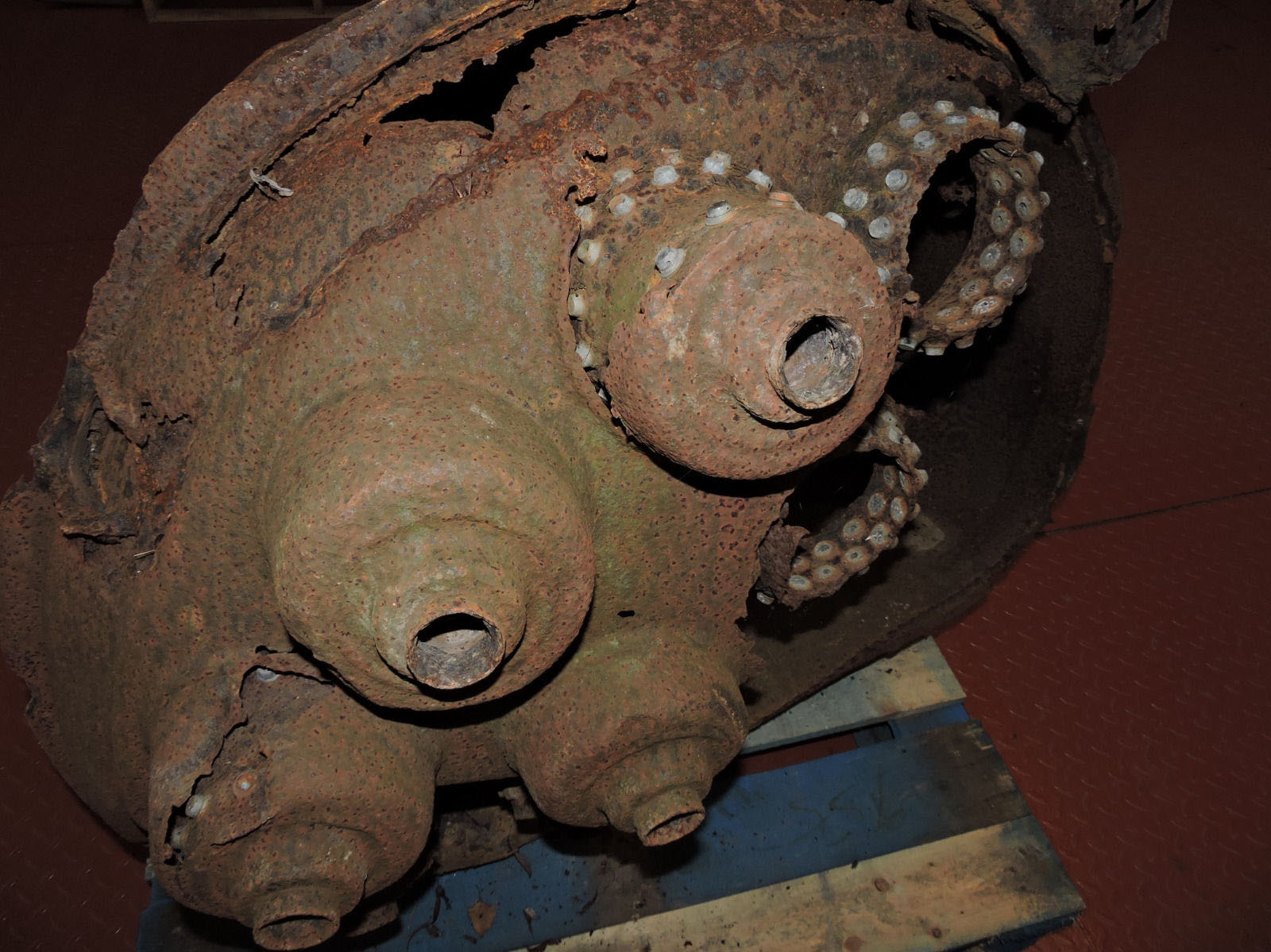
Flown V2 thrust chamber relic from February 1945. Badly damaged from impact, this head shows 4 intact LOX input pipe connections as well as exposed fuel injector inserts positioned in the inner wall of the injector pots. The inner and outer walls of the head are also conveniently exposed on this exhibit. Photo www.v2rockethistory.com

Veil cooling outlet head connector
Veil cooling outlet head connector
| Album | A4-V2 Injection head, combustion chamber, and nozzle |
| Category | Combustion |

Injector pot cutaway: fuel & LOX injectors with LOX cap.
Injector pot cutaway: fuel & LOX injectors with LOX cap.
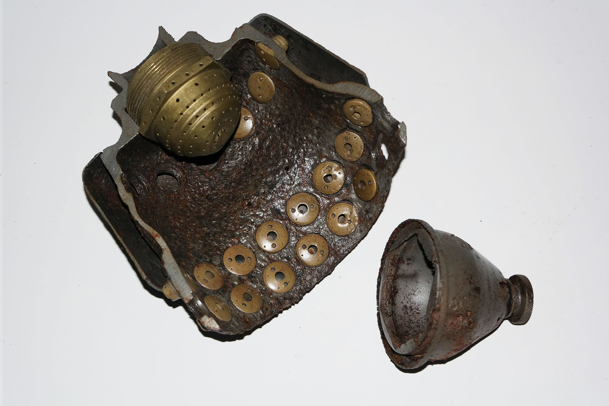
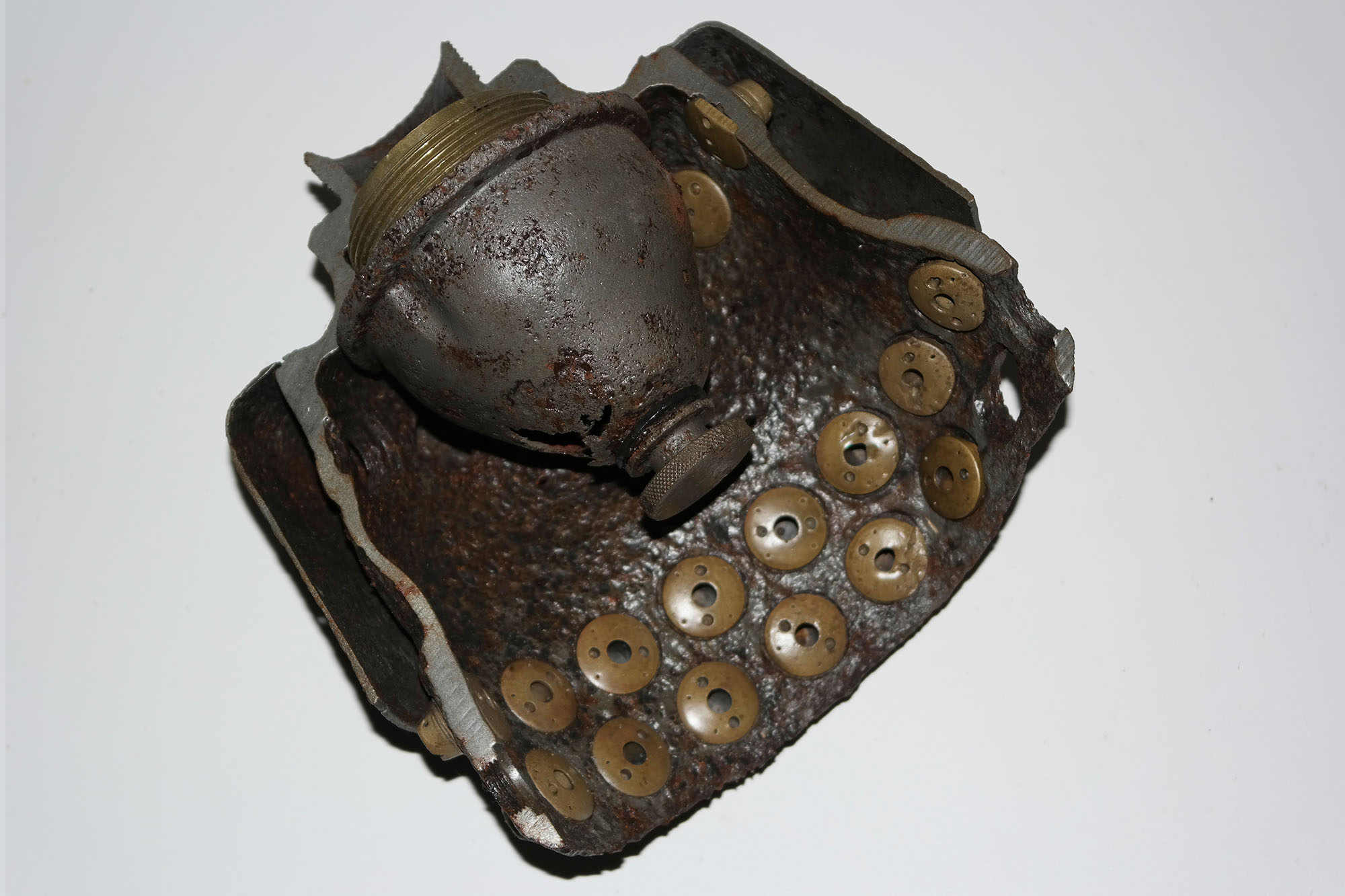
V2 Rocket History Museum Relic: This cutaway presentation shows one of the V2’s 18 combined fuel and liquid oxygen (LOX) injector ‘pots’. The LOX injector transit cap is also shown. The pot shown here is sometimes incorrectly referred to as a pre-burner or pre chamber – a mixer or diffuser pot probably describes its role more accurately.
Injector pot cutaway: fuel & LOX injectors with fitted LOX cap.
Injector pot cutaway: fuel & LOX injectors with fitted LOX cap.
This relic from the V2 Rocket History collection shows a cutaway presentation of one of the V2’s 18 combined fuel and liquid oxygen (LOX) injector ‘pots’. The LOX injector transit cap is also shown fitted over the LOX injector.
Cutaway of one the V2’s pre-chambers with fuel and LOX injectors.
Cutaway of one the V2’s pre-chambers with fuel and LOX injectors.
One of the V2’s 18 injector pots showing fuel and LOX injector copper alloy inserts. The spray head A is for liquid oxygen (LOX) and the numerous small injectors lining the chamber are for the fuel. The term pre-chamber is a throw-back to a time when combustion systems developed at the Kummersdorf test facility had a closed structure rather than the open bucket design seen here. Image Horst Beck Collection
V2 combustion chamber 1944
V2 combustion chamber 1944
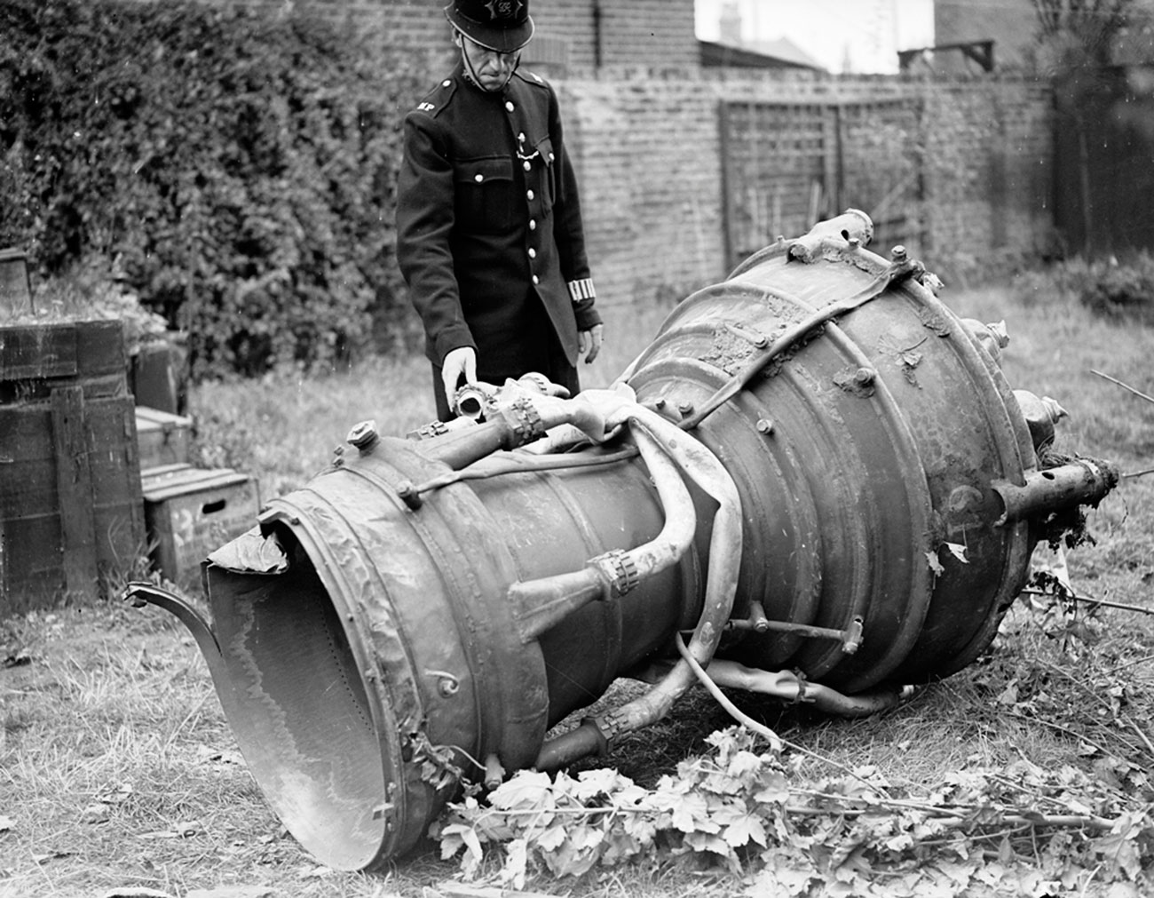
V2 engine part from a missile fired from Walcheren, Serooskerke, Vrederust, by battery no 444, at around 7am on September 17th 1944. The missile impacted East Ham with a direct hit on houses. Killing 6 people with 15 seriously injured. Much of the rocket debris was taken to the East Ham police station for examination by the military authorities. Information porovided by www.v2rocket.com.
Examination of V2 thrust chamber
Examination of V2 thrust chamber
Examination of V2 missile thrust chamber. Sections of two of the large bore aluminium alcohol inlet manifold feed pipes and two thin steel veil colling supply pipes are still attached. The distinctive heat expansion relief loop can be seen on one of the pipes.

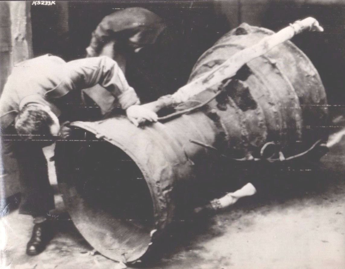
Injector pots V2 combat missile – Feb 1945.
Injector pots V2 combat missile – Feb 1945.
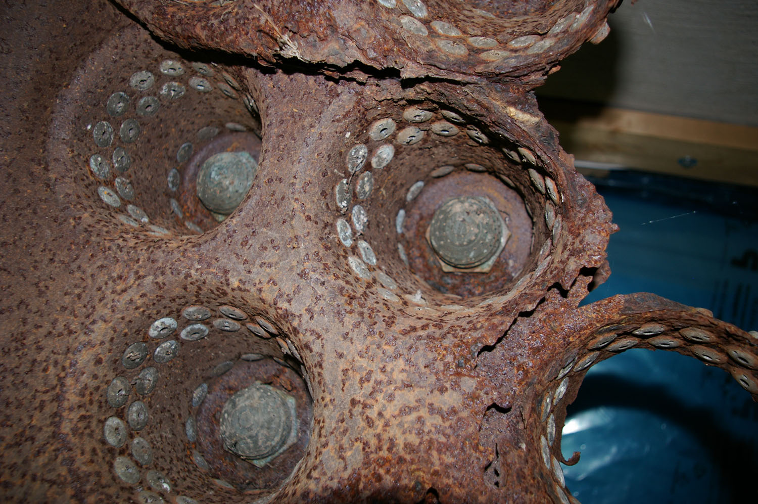
Image shows interior of production series (combat relic) V2 missile propellent injector pre-mixer pots. Three post in the picture are intact, others seem in the picture have been destroyed in the impact. This engine part was recovered from a combat impact East of London. Impact date: February 1945
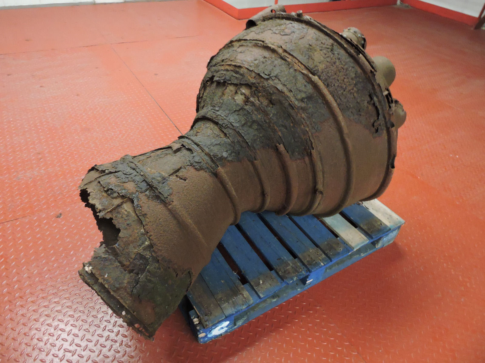
V2 thrust chamber with damaged (missing) inlet manifold
V2 thrust chamber with damaged (missing) inlet manifold
Recovered from Great Warley impact: February 1945. This chamber has a production use order number of 33 painted crudely on topmost segment. This number, to indicate rank in batch, was added shortly after manufacture to ensure the chamber was selected by the missile assembly crews in the correct order; that is on a newest-last basis to make sure that the oldest chambers were employed in missile construction operations first.
Equipment bays
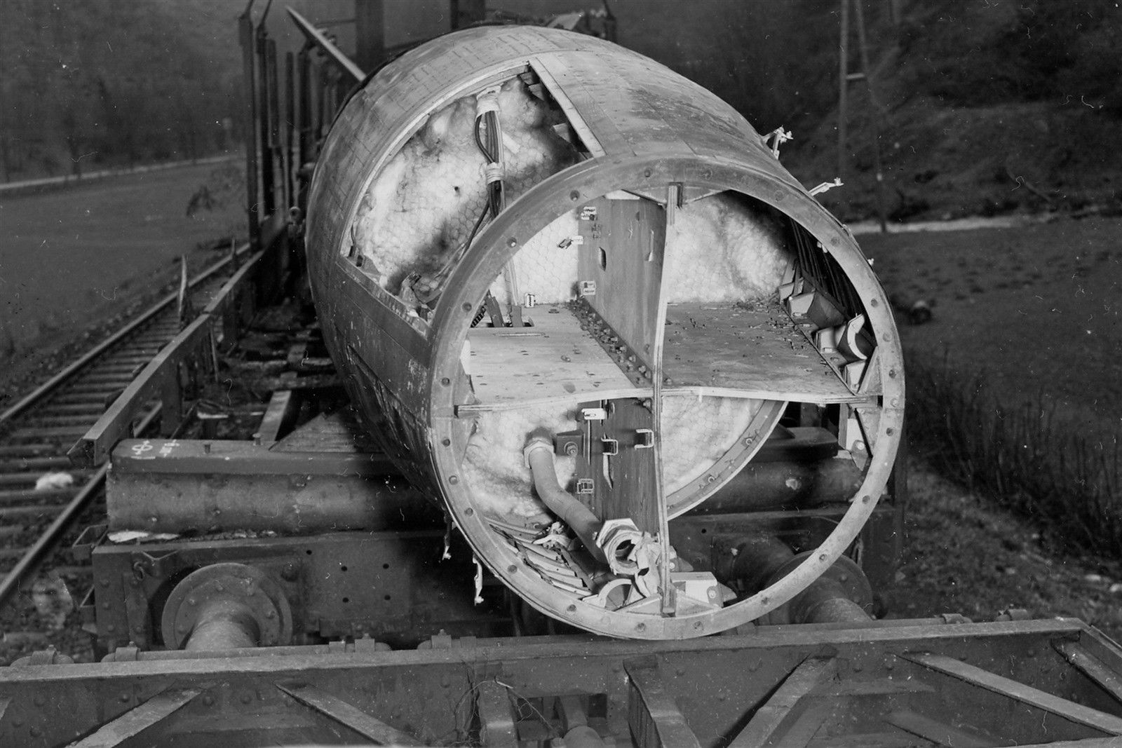
V2 missile on rail wagon showing control bays
V2 missile on rail wagon showing control bays
Incomplete V2 missile on rail transporter. All 4 control compartments are well shown. The fuel tank connection pipe can be seen but not much else. All of the control equipment has been removed. Plainly visible is the chicken wire holding the fiber wool tank insulation in place. Today this would be called ‘Galvanised hexagonal network restraining matrix, and be supplied by a blue chip Aerospace company for $800 per square inch. In the 1940s, it was just chicken wire at a 2 dollars for a 100 ft roll.
| Album | Equipment bays |
Control compartments 1 & 4
Control compartments 1 & 4
Control compartments 1 (upper) & 4 (lower) Image copyright Imperial War Museum
| Album | Equipment bays |
| Category | Missile guidence |
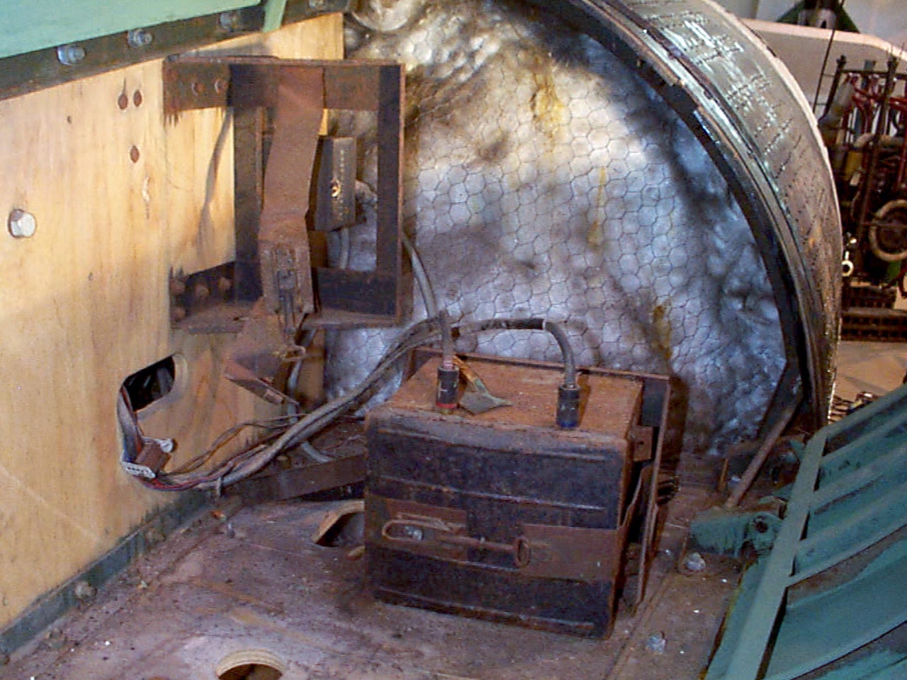
Control compartment 3
Control compartment 3
Control compartments 3 showing gyro mounting platform with two gyros and DC motor driven 3 phase AC voltage generator. The alcohol tank pressurisation pipe is also shown running through the equipment bay (large silver coloured pipe). Image copyright Imperial War Museum
| Album | Equipment bays |
| Category | Guidence |
Control compartment 1
Control compartment 1
Control compartments 1. Image copyright Imperial War Museum
| Album | Equipment bays |
| Category | Electrical connection |
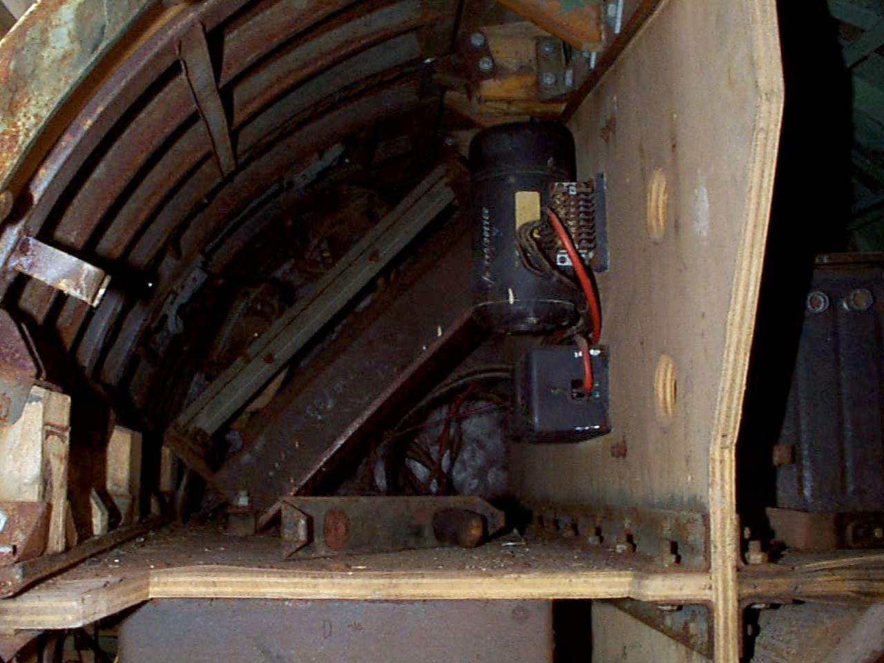
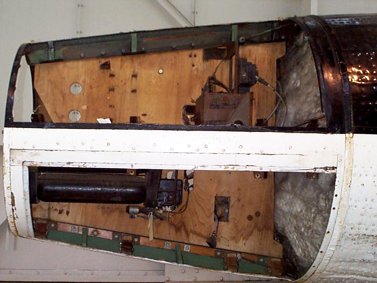
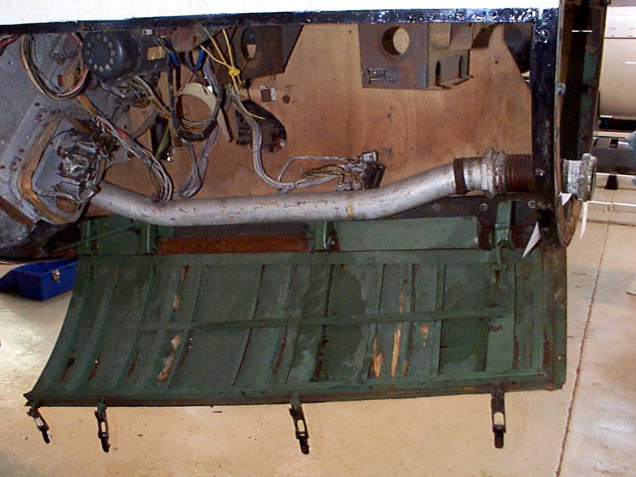
Control compartment 2
Control compartment 2
Control compartment 2 showing plywood separation panels, Oemig umformer (DC to 3 phase AC voltage generator), and voltage frequency control box. Towards the rear the ground connection plugs can just be seen and the mechanism of the cable release trap door (see cat flap!). Image copyright Imperial War Museum
| Album | Equipment bays |
| Category | Electrical connection |
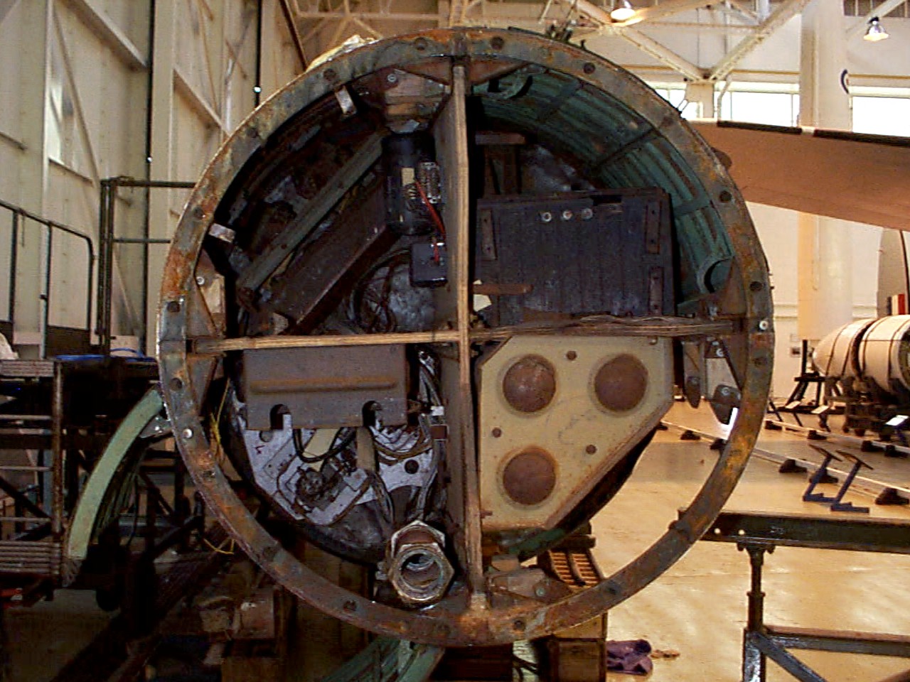
Control compartments – all 4 top view
Control compartments – all 4 top view
Control compartment 1 top right, 2 top left, 3 bottom left, and 4 bottom right. The fuel tank pressurisation pipe upper connection point is well shown at about 6 o’clock (compartment 3) and just above and to the right the upper plate of the air (N) tank rack (tan colour). Image copyright Imperial War Museum
showing plywood separation panels, Oemig umform
| Album | Equipment bays |
Missile guidance equipment
Images of guidance and missile control equiment


Missile guidance equipment
Images of guidance and missile control equiment
LEV-3 Horizont and Vertikant gyroscope system 1940
category:Missile guidence, Sub-assemblies


Description
LEV-3 V2 missile gyroscope system with mounting plate. The third component of this system, the Muller gyroscopic accelerometer, is missing – the 2x mounting points can be seen on the right-hand side of the mounting plate.
Location
