

Archives: Gmedia Albums


The Enigmas
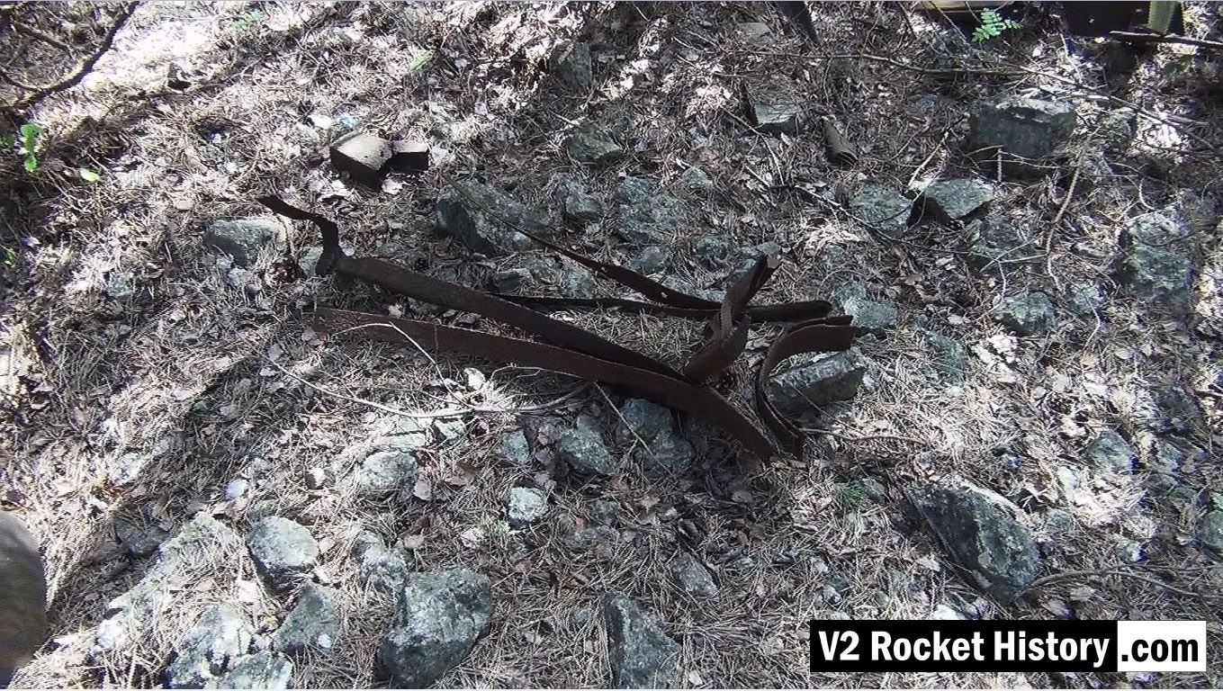
V2 fin relic near F1
V2 fin relic near F1
Picture shows parts of V2 missile fin structure laying on open ground near area between admin offices and F1 (near Admin. block railway platform, see map).
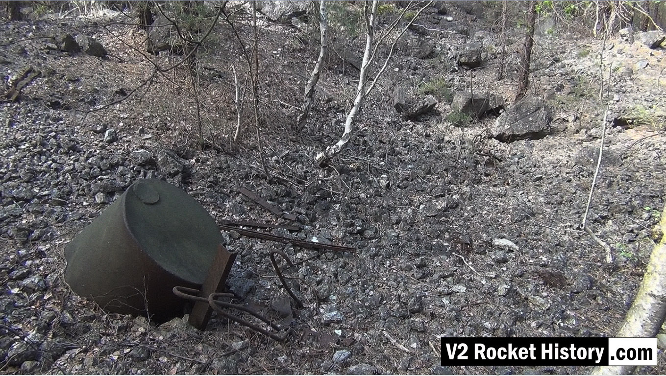
Storage vessel within F1 boundary
Storage vessel within F1 boundary
Picture shows metal debris within the F1 factory boundary walls. The purpose of the part buried liquid storage vessel in the foreground is unknown but it is not a vessel capable of being pressurised. Other assorted metal debris include pipe and cable wall cleats, as well as steel armature rods from reinforced concrete castings (powerful demolition explosions have freed the steel rods from the concrete). These reinforcement rods are a common sight in the environs of Fertigungshalle Eins (F1) and the nearby Repair & Maintenance Hall (R&MH).

Wooden carboy frame examined
Wooden carboy frame examined
Wooden carboy frame from WW2 (possibly used for transporting small quantities of corrosive and dangerous liquids employed in the V2 steam plant (such a T-Stoff) laying among trees 190m East of F1 in a location used as an emergency rail freight loading area for F1 due to damage caused to rail track by US air raids in August 1944.
F1: Fertigungshalle Eins

Bomb damaged F1 factory 1945
Bomb damaged F1 factory 1945
Bomb damaged F1 factory 1945. The huge V2 rocket factory shown badly damaged by air attack at the end of the war in May 1945
Equipment bays
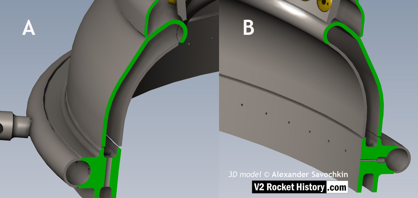
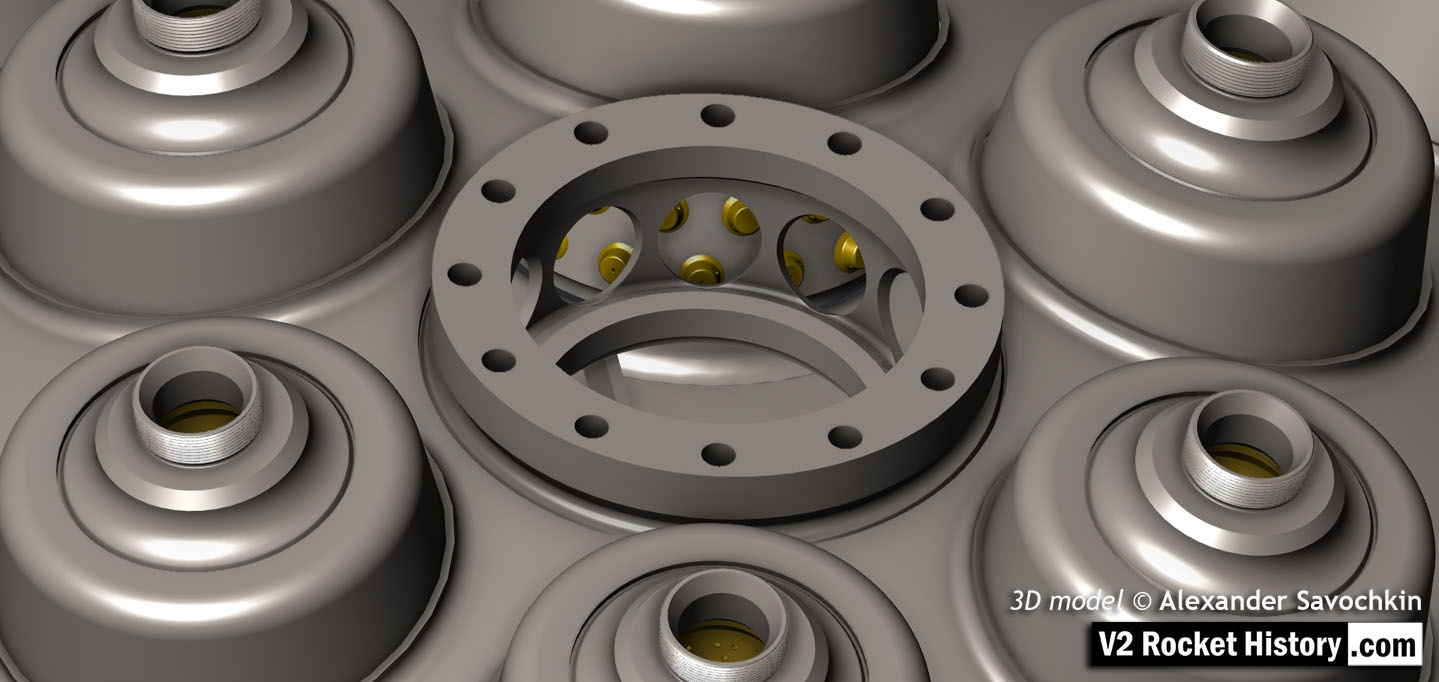
18-pot Upper Veil Manifold detail
18-pot Upper Veil Manifold detail
Close-up detail showing independent pathway for fuel passing into injector head and fuel passed down from the head to be used for veil cooling system. Fig. A shows vertical passages for overall fuel feed to the head and Fig.B shows horizontal pathway for veil coolant fed from the head via the veil coolant distributor ring or manifold. 3D model by Alexander Savochkin
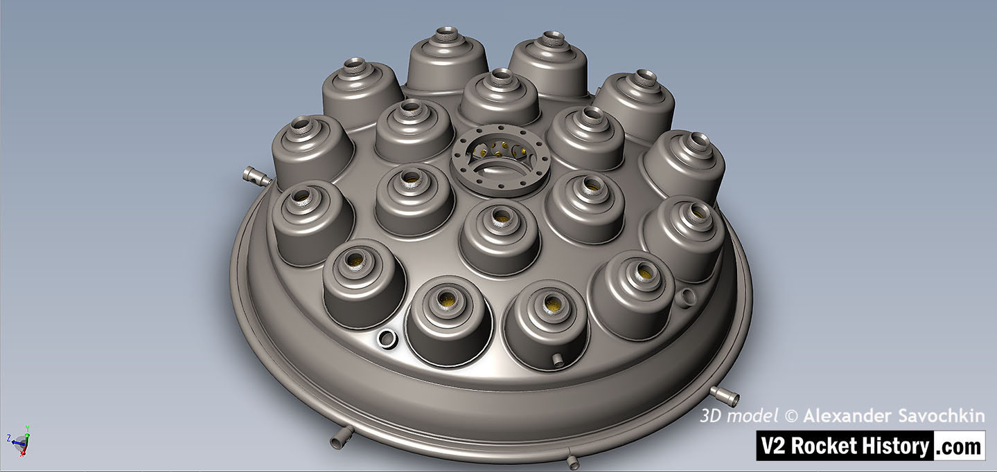
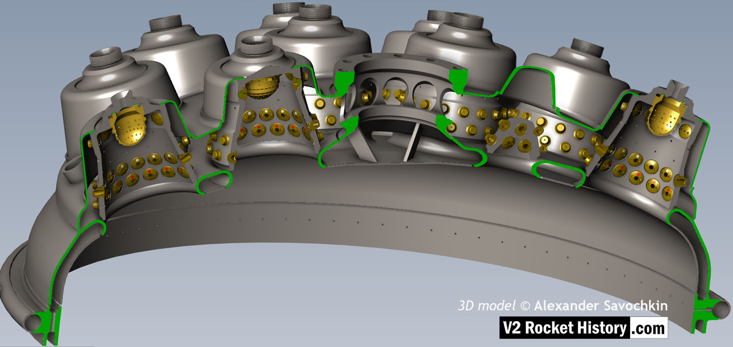
V2 rocket 18-pot Head: Top
V2 rocket 18-pot Head: Top
View of injector head showing 18 liquid propellant (LOX and fuel) diffuser cups and head fuel valve seating ring at centre, (see other images for insert and position nomenclature). Visible immediately below the valve seat are the large connecting holes that allow fuel to flow from the inlet manifold and cooling jacket to the injector space (some brass injector inserts can be seen through the holes) after the head fuel valve is released to be opened by the turbo-pump supply pressure. The four veil cooling inlet connectors are well shown as are two of the outlet connection holes immediately above them. 3D model by Alexander Savochkin
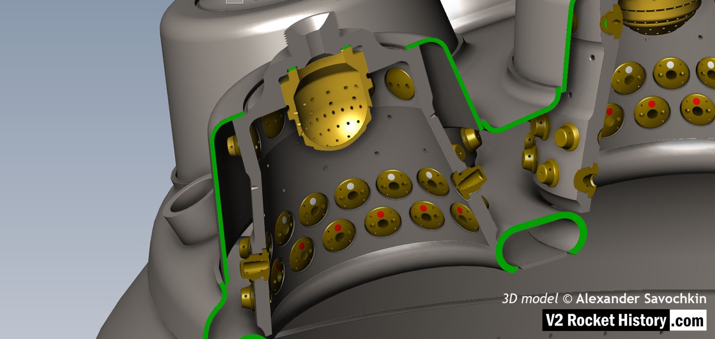
18-pot Head Fuel Valve Seat close-up
18-pot Head Fuel Valve Seat close-up
A close-up view of the head fuel valve mounting flange (showing 12 fastener holes). Visible immediately below the top flange are the large connecting holes that allow fuel to flow from the inlet manifold and cooling jacket to the injector space (some brass injector inserts can be seen through the holes) after the head fuel valve is released to be opened by the turbo-pump supply pressure.
18-pot head: Cutaway 2
18-pot head: Cutaway 2
Here the 18-pot head model has been cutaway to show the fuel cooling and fuel delivery spaces. the cooling jacket layer can be seen in the lowermost area of the head – below the centrally positioned fuel valve seat, between each cup at the lowest point, and ruining down toward the first set of veil cooling pores and the topmost coolant distributor ring. Note that the veil cooling system does not communicate with the regenerative cooling jacket and has its own feed pipes drawing fuel from the head injector space and not the cooling space. Visible immediately above the valve seat are the large connecting holes that allow fuel to flow from the inlet manifold and cooling jacket to the injector space after the head fuel valve is released to be opened by the turbo-pump supply pressure. 3D model by Alexander Savochkin
18-pot Cutaway 1
18-pot Cutaway 1
Liquid propellent (LOX and fuel) diffuser cup, showing three rings or echelons (A,D,& E) of brass injector inserts as well as two rows of drilled fuel feed holes. The LOX spray head is shown in the centre. Note the simple ‘shower head or watering can’ design of the LOX diffuser. A sealing washer can be seen fitted between the LOX diffuser and the steel cup. 3D model by Alexander Savochkin
Missile guidance equipment
Images of guidance and missile control equiment


Missile guidance equipment
Images of guidance and missile control equiment
LEV-3 Horizont and Vertikant gyroscope system 1940
category:Missile guidence, Sub-assemblies


Description
LEV-3 V2 missile gyroscope system with mounting plate. The third component of this system, the Muller gyroscopic accelerometer, is missing – the 2x mounting points can be seen on the right-hand side of the mounting plate.
Location
