

Archives: Gmedia Albums


The Enigmas

Unknown repair workshop (IW) mechanism
Unknown repair workshop (IW) mechanism
We think this relic, welded to a heavy gauge H beam, may be a points switch for a railway line. But do you know what it is, and what it did? If you do, please tell us.
| Album | The Enigmas |
| Category | Mystery part |
Unknown helical part
Unknown helical part
This part has a helicoid or screw shape, it seems that it might have been designed to screw into a pipe of some kind. But do you know what it really is, and what it did? If you do, please tell us.
| Album | The Enigmas |
| Category | Mystery part |

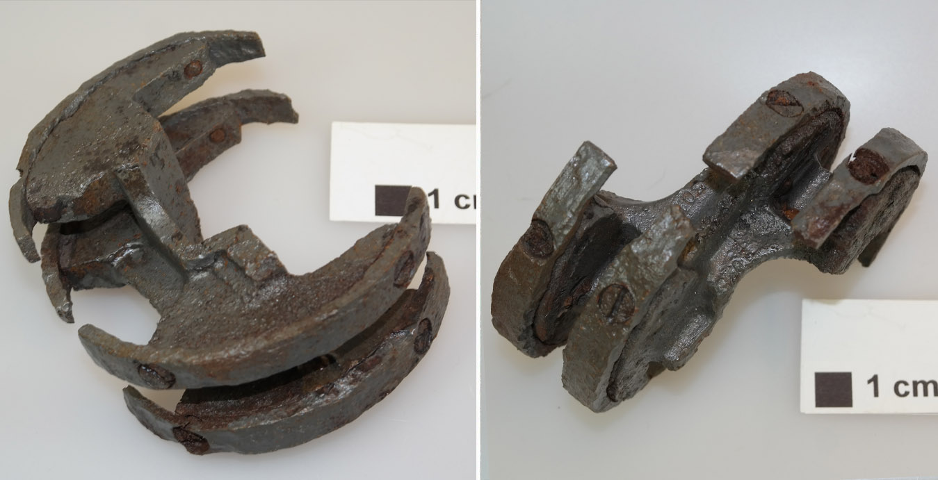
Chain and hook clamp – unknown use
Chain and hook clamp – unknown use
We know this is a clampy-chainy-hooky thing – but do you know what it really is, and what it did? If you do, please tell us.
| Album | The Enigmas |
| Category | Mystery part |

Close up of relic within IW near aisle 20
Close up of relic within IW near aisle 20
This is a close up of the mystery item, referred to on our Enigma page, found firmly anchored to the floor a few metres inside the east wall near aisle 20 of IW (near location of internal railway line).
| Album | The Enigmas |
| Category | Mystery part |

Close up of relic within IW near aisle 20
Close up of relic within IW near aisle 20
This is another close up of the mystery item showing the mechanism in more detail. It can be found firmly anchored to the floor a few metres inside the east wall near aisle 20 of IW (near location of internal railway line). See map below for location.
| Album | The Enigmas |
| Category | Mystery part |
F1: Fertigungshalle Eins
V2 rocket injector head – LOX Spray nozzle 1
V2 rocket injector head – LOX Spray nozzle 1
Brass liquid oxygen (LOX) spray nozzle.Note: the thread is shown in simplified graphic form. 3D model by Alexander Savochkin
V2 rocket injector head – LOX Spray nozzle 2
V2 rocket injector head – LOX Spray nozzle 2
Brass liquid oxygen (LOX) spray nozzle. Note: the thread is shown in simplified form. 3D model by Alexander Savochkin
V2 engine Fuel And LOX Diffuser cup – Internal and external
V2 engine Fuel And LOX Diffuser cup – Internal and external
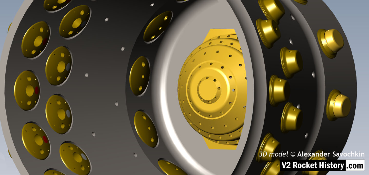
One of the 18 liquid propellant (LOX and fuel) diffuser cups, showing three rows or echelons (A,D,& E) of brass injector inserts as well as two rows of drilled fuel feed holes. The LOX spray head is shown in the centre. 3D model by Alexander Savochkin
Fuel And LOX Diffuser Cup Cutaway 3
Fuel And LOX Diffuser Cup Cutaway 3
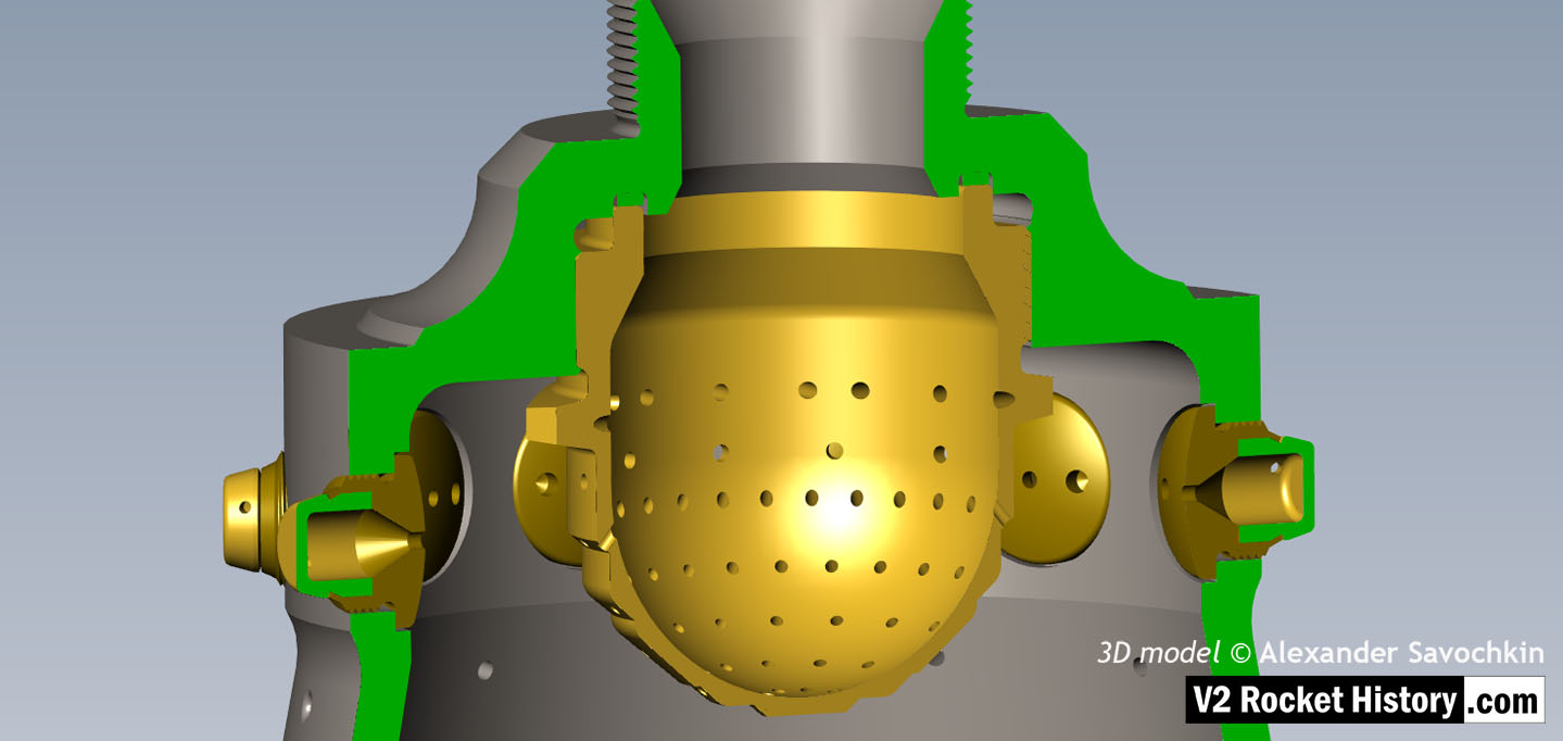
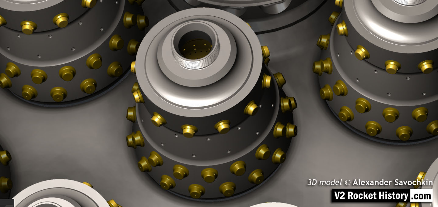
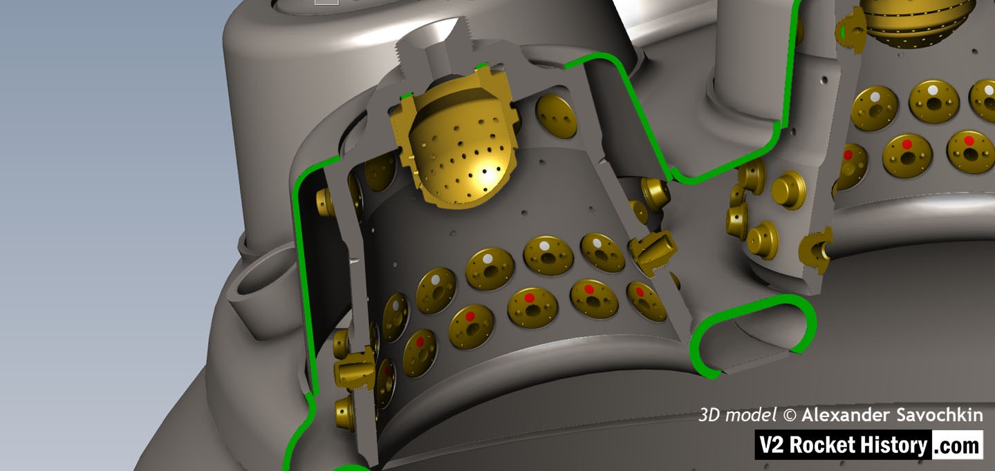
Cutaway showing echelon A with 2-part 2131E fuel injector inserts at the top of a propellant diffuser cup. Note the close proximity of the injector inserts to the simple ‘watering can’ type LOX spray head. One row of drilled fuel feed holes can be seen below the inserts. 3D model by Alexander Savochkin
Lower section Fuel And LOX Diffuser Cup Cutaway 2
Lower section Fuel And LOX Diffuser Cup Cutaway 2
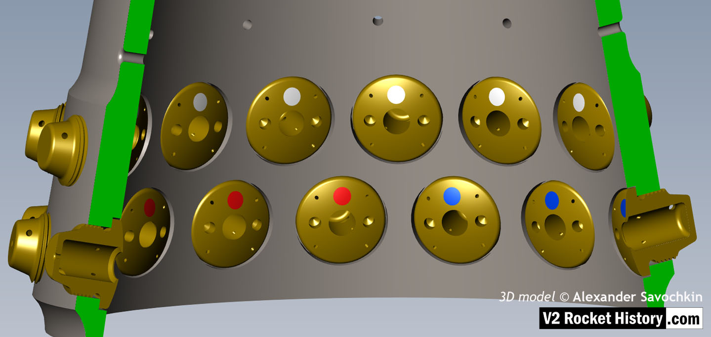
This images shows a cutaway of a burner cup from outer Ring I of the injector head and shows injector insert eschelon D, & E as well as one row of drilled feed holes. Three fuel injector insert types can be seen: Top D, = 3303D (white), lower E, = 3304D (red), and E, = 3305D (blue). 3D model by Alexander Savochkin
Fuel And LOX Diffuser Cup Cutaway 1
Fuel And LOX Diffuser Cup Cutaway 1
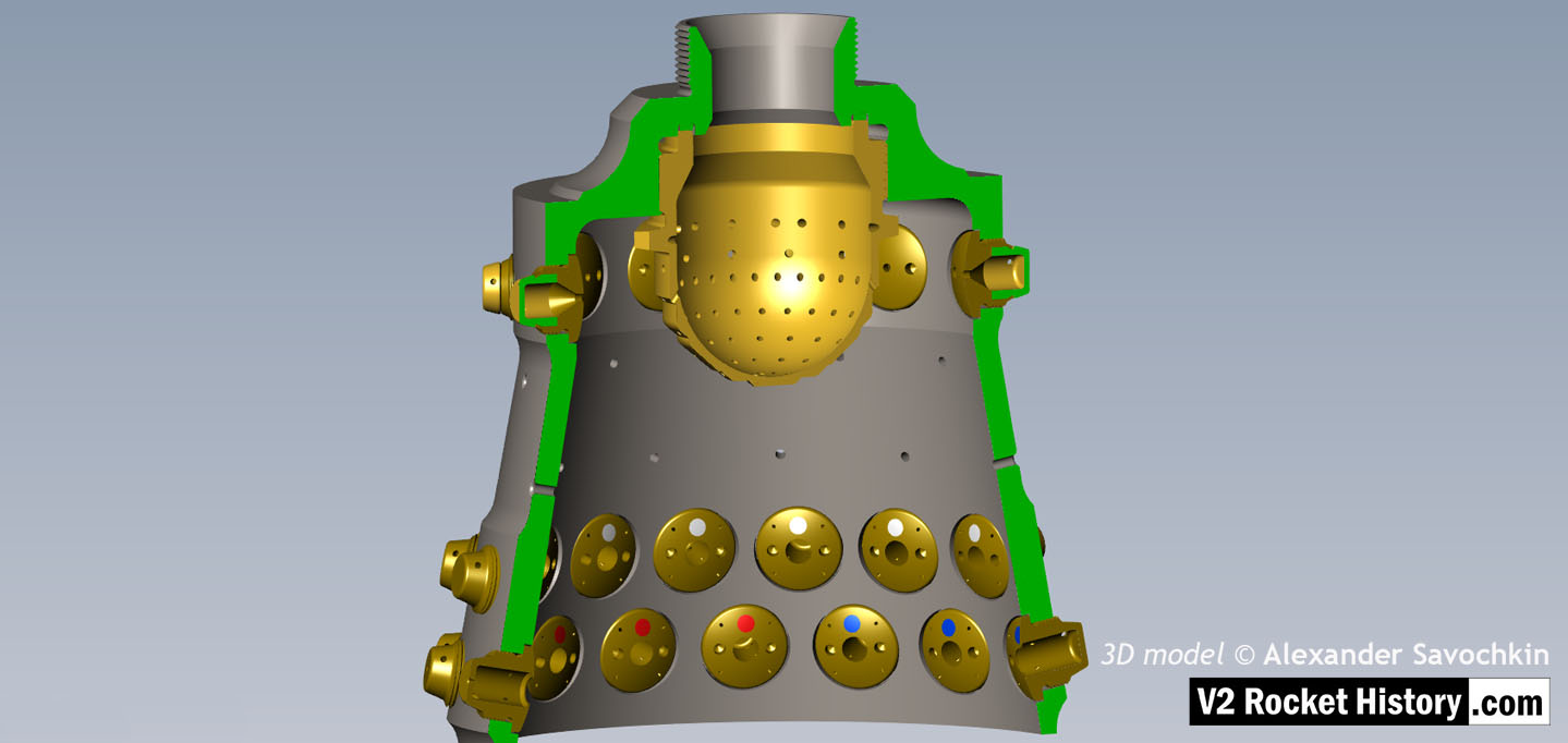
This images shows a burner cup from outer Ring I of the injector head and the cutaway shows injector insert eschelon A,D, & E as well as two rows of drilled feed holes. Four fuel injector insert types can be seen: Top, A = 2131E, lower D, = 3303D (white), lowest E, = 3304D (red), and E, = 3305D (blue). 3D model by Alexander Savochkin
V2 Fuel and LOX Diffuser Cup general view
V2 Fuel and LOX Diffuser Cup general view
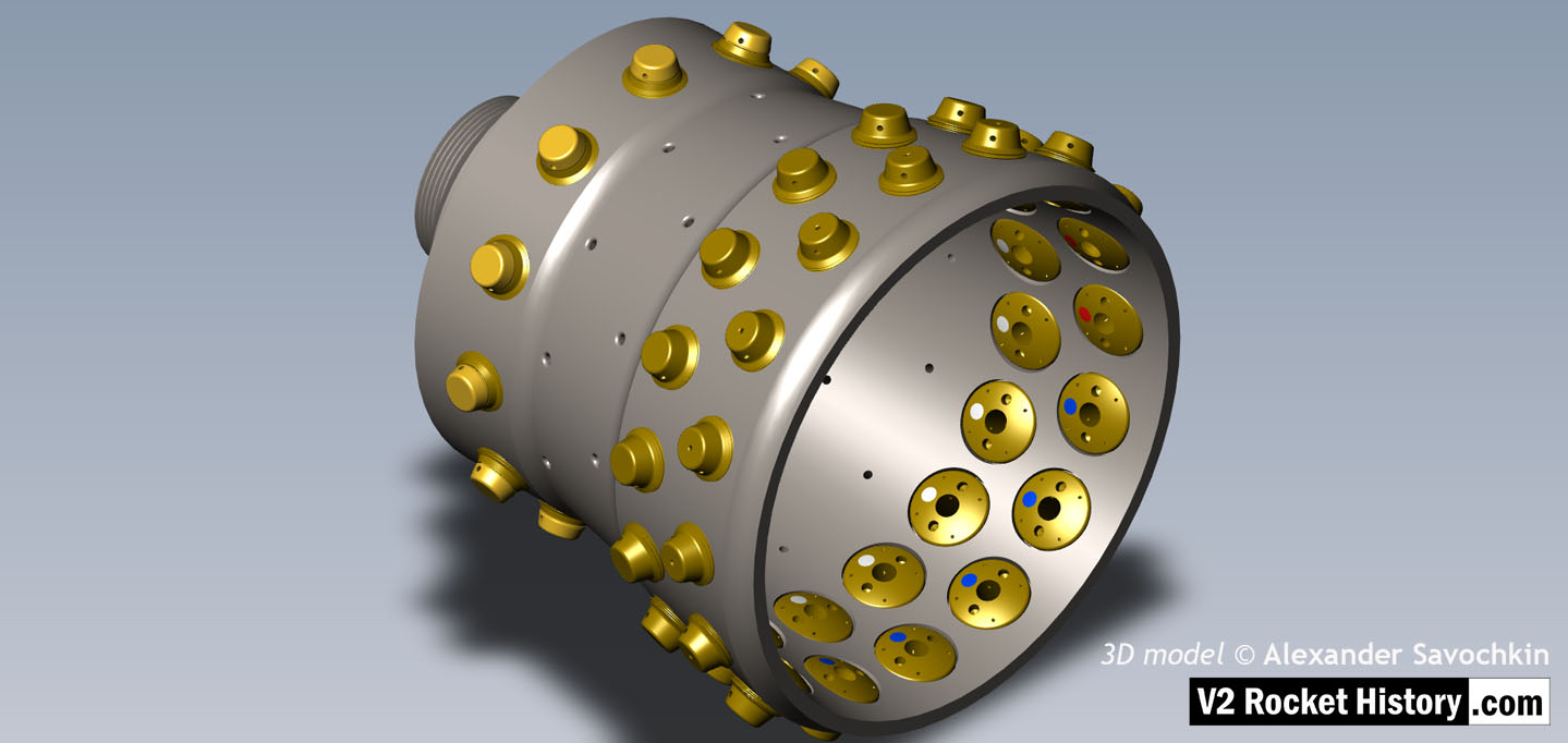
General view of the propellant diffuser cup inner core. The swirl caps of fuel injector inserts in positions A,D,& E can be seen clearly on the outside of the core as well as the central holes in the 3304D (red) inserts.The two rows of drilled fuel feed holes are also well shown. 3D model by Alexander Savochkin
18-pot Upper Veil Manifold detail
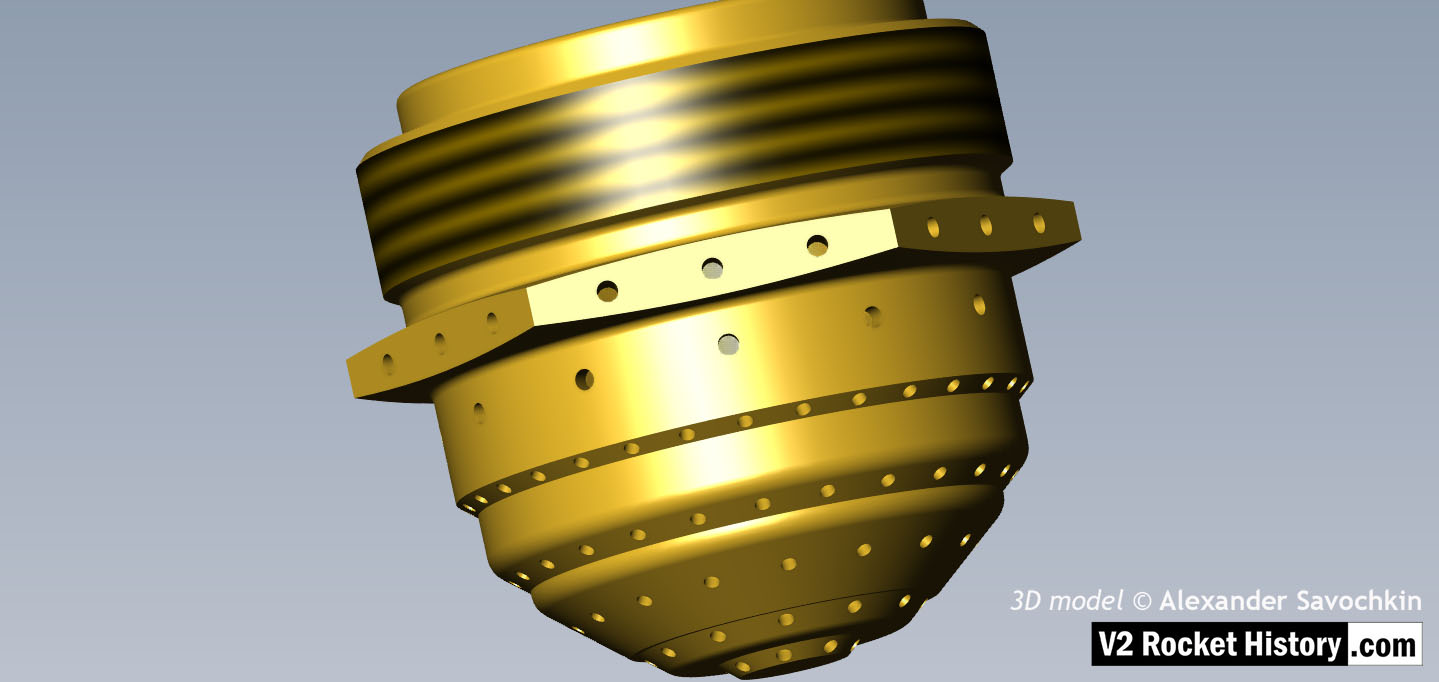
18-pot Upper Veil Manifold detail
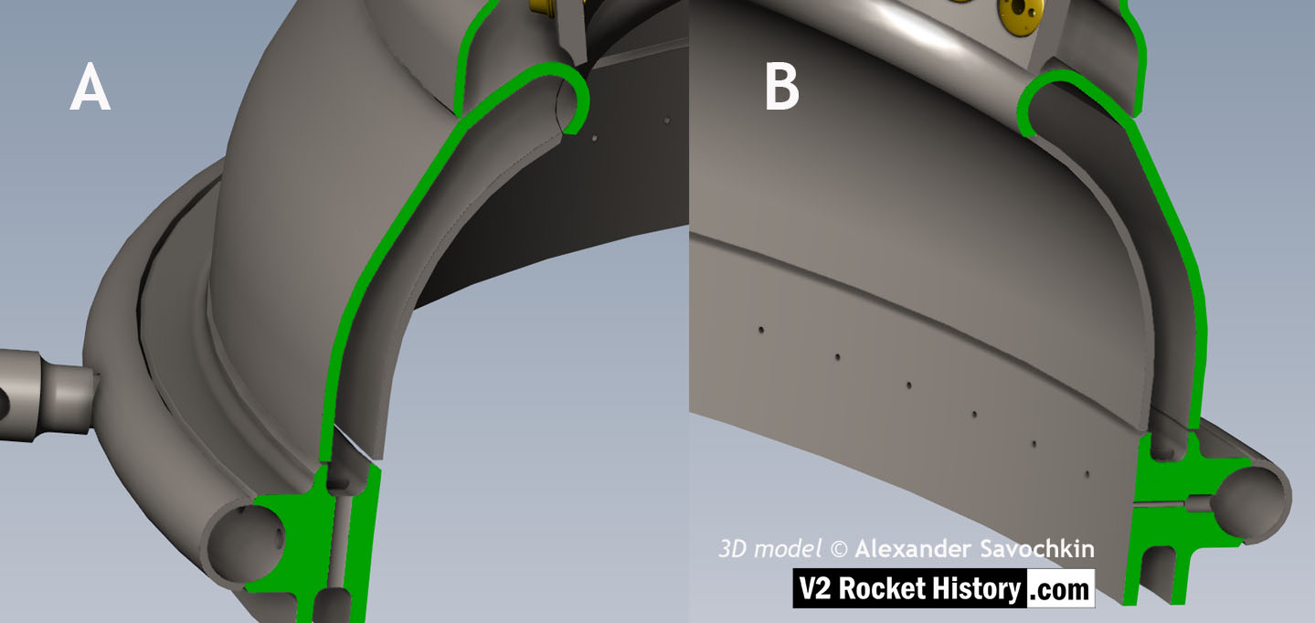
Close-up detail showing independent pathway for fuel passing into injector head and fuel passed down from the head to be used for veil cooling system. Fig. A shows vertical passages for overall fuel feed to the head and Fig.B shows horizontal pathway for veil coolant fed from the head via the veil coolant distributor ring or manifold. 3D model by Alexander Savochkin
18-pot Head: Underside close-up detail
18-pot Head: Underside close-up detail
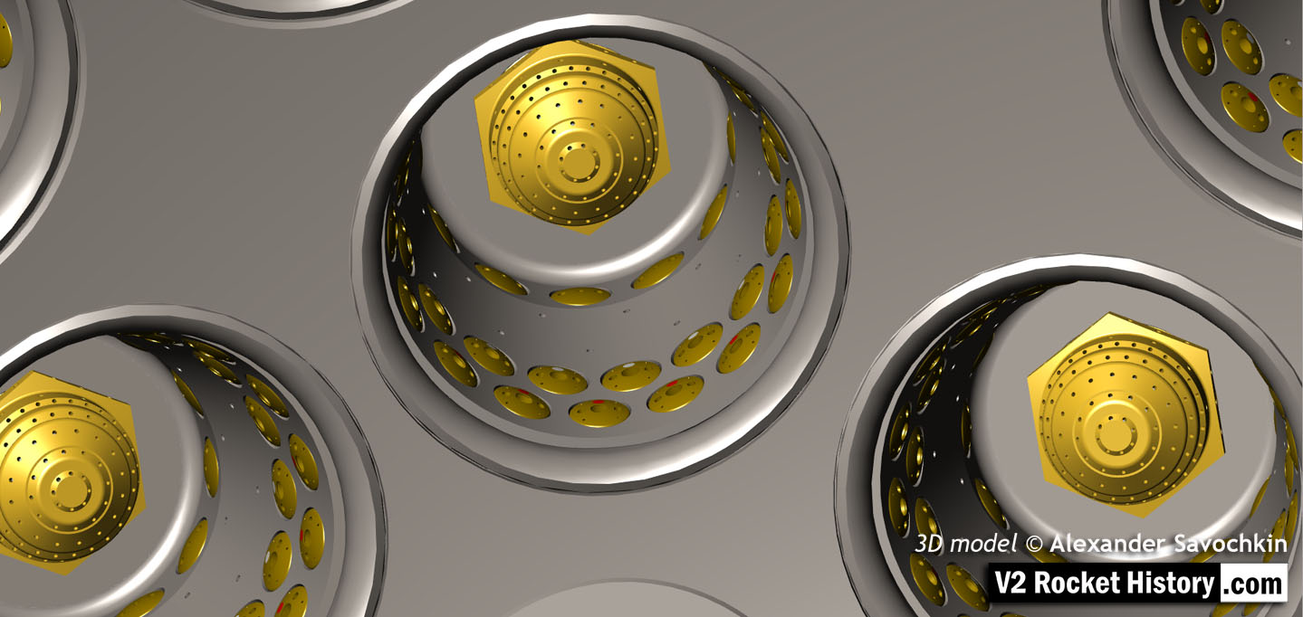
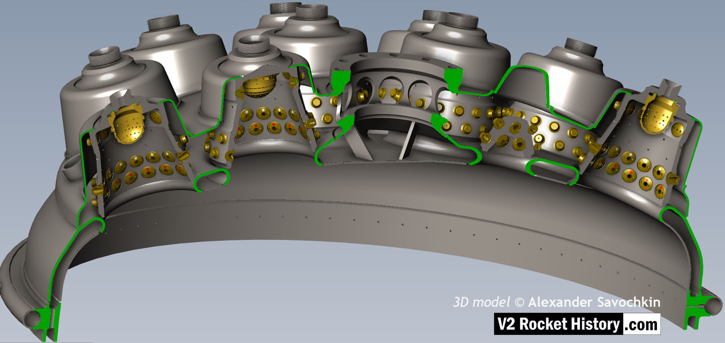
Underside view of injector head showing liquid propellant (LOX and fuel) diffuser cups, (see other images for insert and position nomenclature). Of note in this image are the pointing angles of the cups, positioned on a parabolic section to focus the propellant nebular stream into the central axis of the combustion space. Also of note are the large areas between each cup NOT employed in the injection process – initiating ‘clumpy’ and uneven propellant mixing initially below the injector face but also carried forward into the combustion space. The LOX spray head is shown in the centre of each cup. 3D model by Alexander Savochkin
V2 rocket 18-pot Head Underside
V2 rocket 18-pot Head Underside
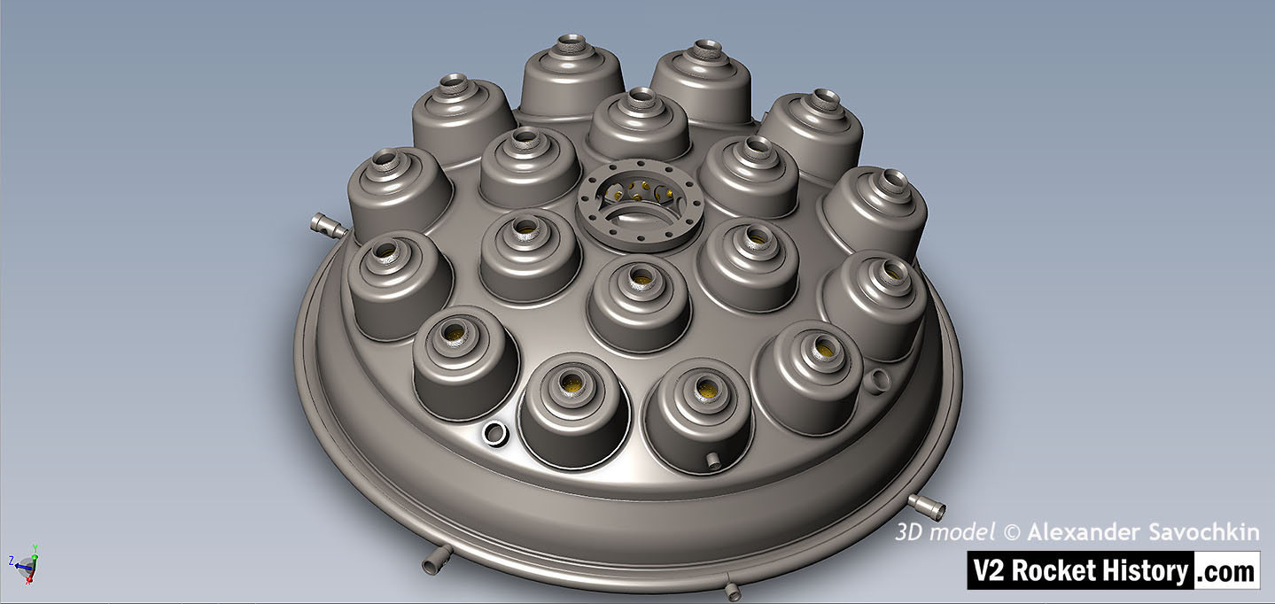
Inverted view of injector head showing liquid propellant (LOX and fuel) diffuser cups, (see other images for insert and position nomenclature). Of note in this image are the pointing angles of the cups, positioned on a parabolic section to focus the propellant nebular stream into the central axis of the combustion space. Also of note are the large areas between each cup NOT employed in the injection process leading to structured propellant mixing as opposed to even homogeneous mixing. The four veil cooling inlet connectors are well shown. 3D model by Alexander Savochkin
V2 rocket 18-pot Head: Top
V2 rocket 18-pot Head: Top
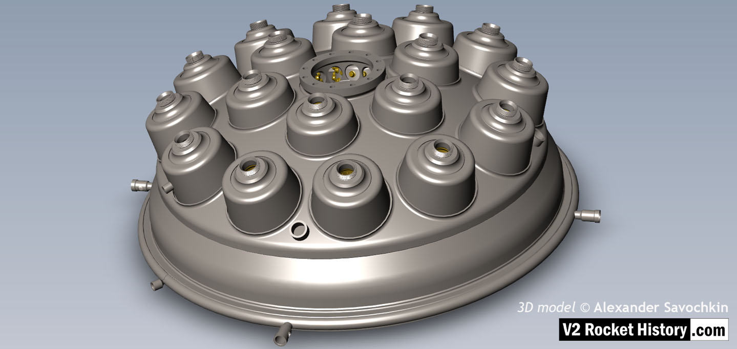
View of injector head showing 18 liquid propellant (LOX and fuel) diffuser cups and head fuel valve seating ring at centre, (see other images for insert and position nomenclature). Visible immediately below the valve seat are the large connecting holes that allow fuel to flow from the inlet manifold and cooling jacket to the injector space (some brass injector inserts can be seen through the holes) after the head fuel valve is released to be opened by the turbo-pump supply pressure. The four veil cooling inlet connectors are well shown as are two of the outlet connection holes immediately above them. 3D model by Alexander Savochkin
18-pot Head: Top Plate removed to show cores
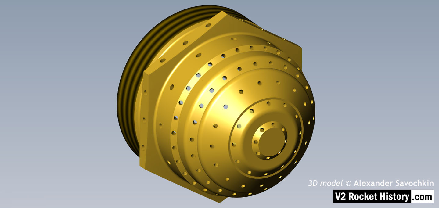
18-pot Head: Top Plate removed to show cores
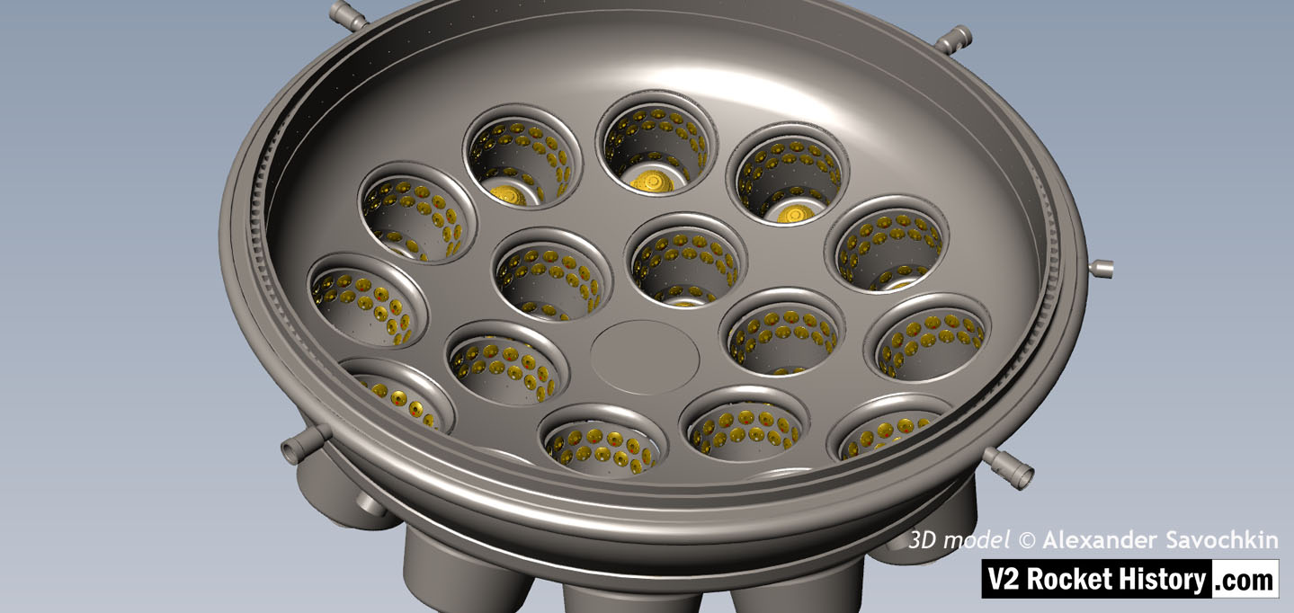
View of the top of the injector head, with outer cups and pressed steel capping piece removed, showing, propellant diffuser inner cores with injector inserts and LOX supply pipe connection thread. The LOX spray head can be seen inside the LOX pipe connector. The swirl caps of fuel injector inserts in positions A,D,& E can be seen clearly on the outside of the cores and the two rows of drilled fuel feed holes are also well shown. 3D model by Alexander Savochkin
25-ton thrust 18-pot injector head: Top 1
25-ton thrust 18-pot injector head: Top 1
Another view of injector head showing liquid propellant (LOX and fuel) diffuser cups and head fuel valve seating ring at centre, (see other images for insert and position nomenclature). Visible immediately below the valve seat are the large connecting holes that allow fuel to flow from the inlet manifold and cooling jacket to the injector space (some brass injector inserts can be seen through the holes) after the head fuel valve is released to be opened by the turbo-pump supply pressure. The four veil cooling inlet connectors are well shown as are two of the outlet connection holes immediately above them. 3D model by Alexander Savochkin
18-pot Head Fuel Valve Seat close-up
18-pot Head Fuel Valve Seat close-up
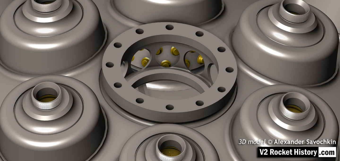
A close-up view of the head fuel valve mounting flange (showing 12 fastener holes). Visible immediately below the top flange are the large connecting holes that allow fuel to flow from the inlet manifold and cooling jacket to the injector space (some brass injector inserts can be seen through the holes) after the head fuel valve is released to be opened by the turbo-pump supply pressure.
18-pot head Exploded to show 1100+ Parts
18-pot head Exploded to show 1100+ Parts
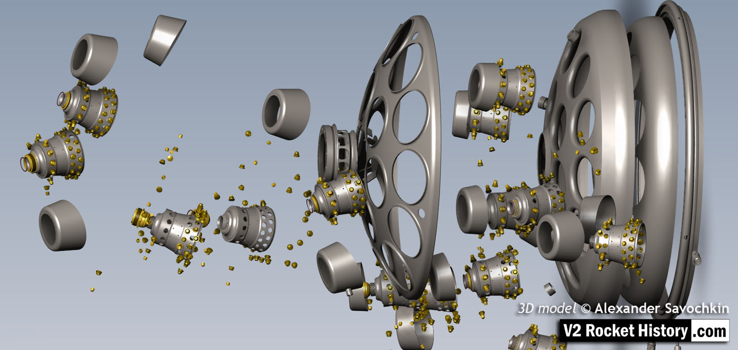
Exploded view showing some of the 1100 parts required for the complicated 18-pot injector head of the V2 25-ton thrust rocket engine. 3D model by Alexander Savochkin
18-pot head: Cutaway 2
18-pot head: Cutaway 2
Here the 18-pot head model has been cutaway to show the fuel cooling and fuel delivery spaces. the cooling jacket layer can be seen in the lowermost area of the head – below the centrally positioned fuel valve seat, between each cup at the lowest point, and ruining down toward the first set of veil cooling pores and the topmost coolant distributor ring. Note that the veil cooling system does not communicate with the regenerative cooling jacket and has its own feed pipes drawing fuel from the head injector space and not the cooling space. Visible immediately above the valve seat are the large connecting holes that allow fuel to flow from the inlet manifold and cooling jacket to the injector space after the head fuel valve is released to be opened by the turbo-pump supply pressure. 3D model by Alexander Savochkin
18-pot Cutaway 1
18-pot Cutaway 1
Liquid propellent (LOX and fuel) diffuser cup, showing three rings or echelons (A,D,& E) of brass injector inserts as well as two rows of drilled fuel feed holes. The LOX spray head is shown in the centre. Note the simple ‘shower head or watering can’ design of the LOX diffuser. A sealing washer can be seen fitted between the LOX diffuser and the steel cup. 3D model by Alexander Savochkin
Equipment bays

Muller Mechanical Integrating Gyroscopic Accelerometer
Muller Mechanical Integrating Gyroscopic Accelerometer
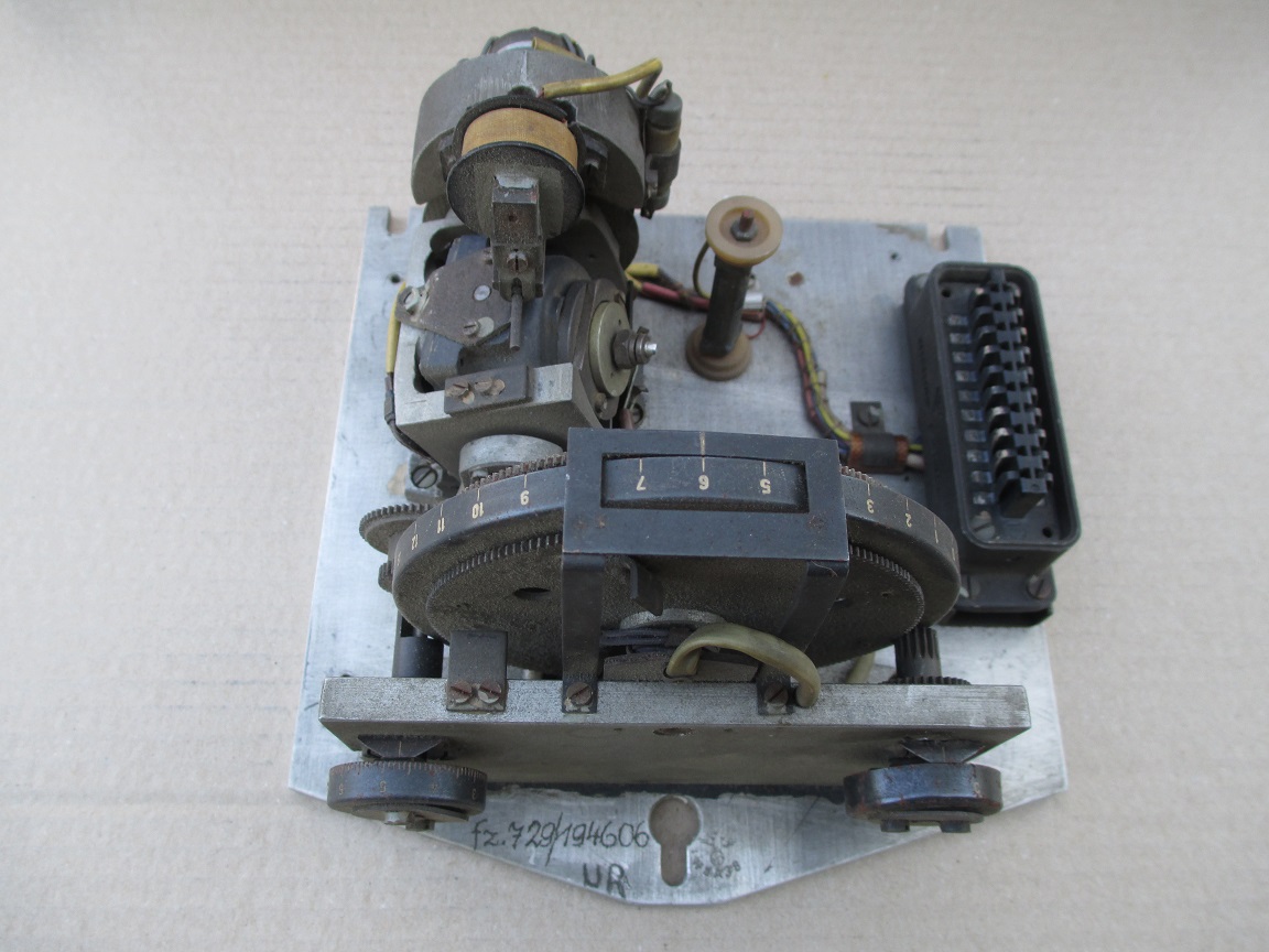
The Muller mechanical or Pendulous Integrating Gyroscopic Accelerometer – today normally referred to as a PIGA. Designed by Fritz K Muller.
The J device, no1 (J Gerate Eins) or Muller Mechanical Integrating Accelorometer. © THBC
The J device, no1 (J Gerate Eins) or Muller Mechanical Integrating Accelorometer. © THBC
The J device no1 (J Gerate Eins). The full name of this device is: the Muller Pendulous (or mechanical) Integrating Gyroscopic Accelerometer – today normally referred to as a PIGA. The device, designed by Fritz K Muller, operates as a switch to initiate rocket engine shutdown and is able to smoothly record and accumulate every moment of acceleration, without any kind of recording resolution or discrete time interval limit, of the rocket’s entire motor burn phase, and at the same time process this accumulated acceleration with respect to time as a gradually increasing velocity. In the case of the V2 missile, when the correct predetermined velocity is reached, the velicity sufficient to achieve the desired range of the missile, the device trips the relays that close valves that shutdown the supply of steam to the turbo-pump, and thus shutdown the rocket motor itself.
Missile guidance equipment
Images of guidance and missile control equiment


Missile guidance equipment
Images of guidance and missile control equiment
LEV-3 Horizont and Vertikant gyroscope system 1940
category:Missile guidence, Sub-assemblies


Description
LEV-3 V2 missile gyroscope system with mounting plate. The third component of this system, the Muller gyroscopic accelerometer, is missing – the 2x mounting points can be seen on the right-hand side of the mounting plate.
Location
