

Archives: Gmedia Albums


The Enigmas

LEV-3 Horizont and Vertikant gyroscope system 1940
LEV-3 Horizont and Vertikant gyroscope system 1940
LEV-3 V2 missile gyroscope system with mounting plate. The third component of this system, the Muller gyroscopic accelerometer, is missing – the 2x mounting points can be seen on the right-hand side of the mounting plate.
| Album | Missile guidance equipment |
| Categories | Missile guidence, Sub-assemblies |

Remains of 36 volt battery cells used on the V2 to power onboard equipment. ©THBC
Remains of 36 volt battery cells used on the V2 to power onboard equipment. ©THBC
Photo shows rare surviving complete set of 8 lead acid battery cells from one of the V2 rocket’s 32 volt (100 amp) lead acid batteries. Two sets of batteries like this were used to provide the direct current (DC) voltage used aboard the V2 missile to power the DC to 3-phase alternating current (AC) generators, that in turn, powered the gyroscopes, electro-hydraulic servos, trim motors and other vital guidance and control devices. Photo copyright: The Horst Beck Collection

A4-V2 50 volt command or signalling battery. ©THBC
A4-V2 50 volt command or signalling battery. ©THBC
Photo shows rare surviving 1.2 volt cell from the V2 missile’s 50 volt command or signalling battery used in its gyro guidance system (note, the terminal connection on the left is missing from this exhibit, it would be identical to the one on the right). This wet nickel-cadmium battery cell was combined in pairs to a total set of 21 providing a 50.4 voltage at 300mA. The cells were contained in a wooden box that was held on a rack in equipment bay III. Its function was to provide the direct current (DC) signalling voltage that communicated the moment to moment resistance of the gyroscope’s potentiometers to the analog guidance computer (Mischgerät = Mixer-device or control amplifier) aboard the V2 missile. It was critical that the signalling voltage was maintained between 48 and 50.4 volts. Photo copyright: The Horst Beck Collection

Brief description of overall shoot
Brief description of overall shoot
V-2 Accelerometer (1941)

Brief description of overall shoot
Brief description of overall shoot
V-2 Accelerometer (1941)

Muller Mechanical Integrating Gyroscopic Accelerometer
Muller Mechanical Integrating Gyroscopic Accelerometer
The Muller mechanical or Pendulous Integrating Gyroscopic Accelerometer – today normally referred to as a PIGA. Designed by Fritz K Muller.
F1: Fertigungshalle Eins
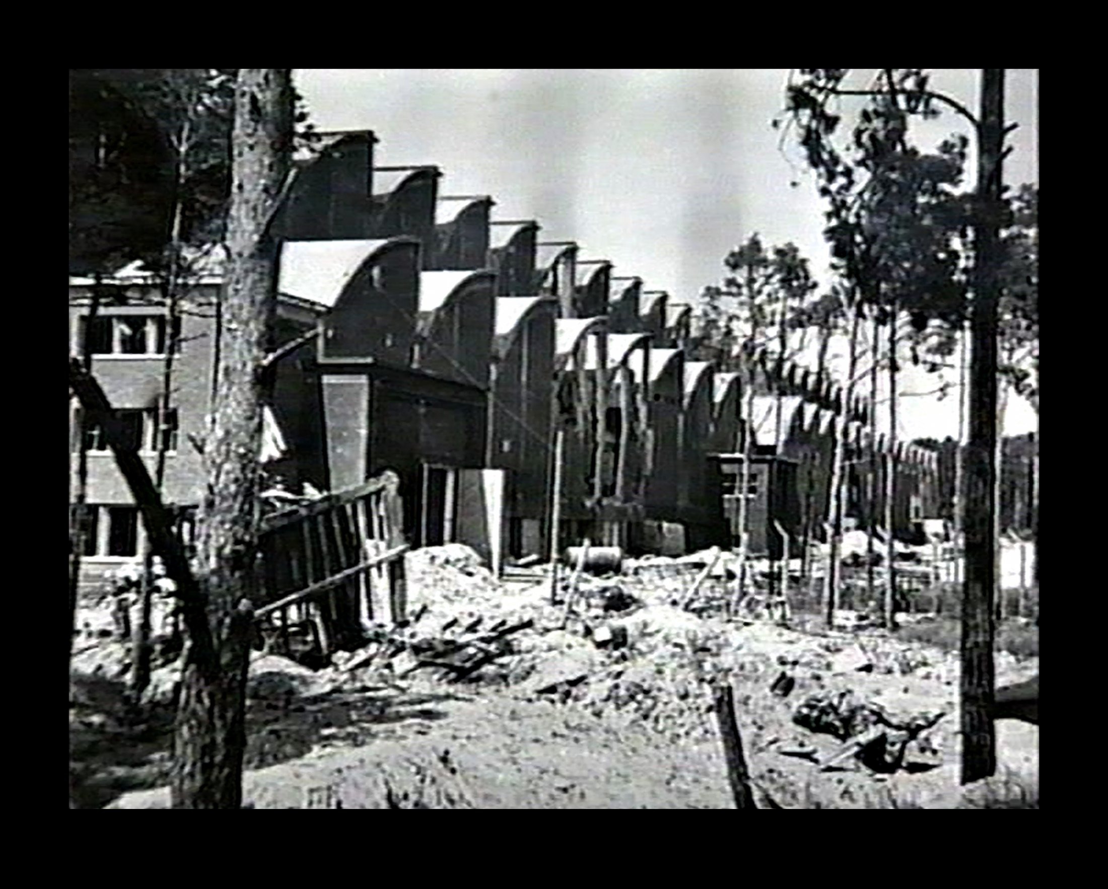
Bomb damaged F1 factory 1945
Bomb damaged F1 factory 1945
Bomb damaged F1 factory 1945. The huge V2 rocket factory shown badly damaged by air attack at the end of the war in May 1945
Equipment bays
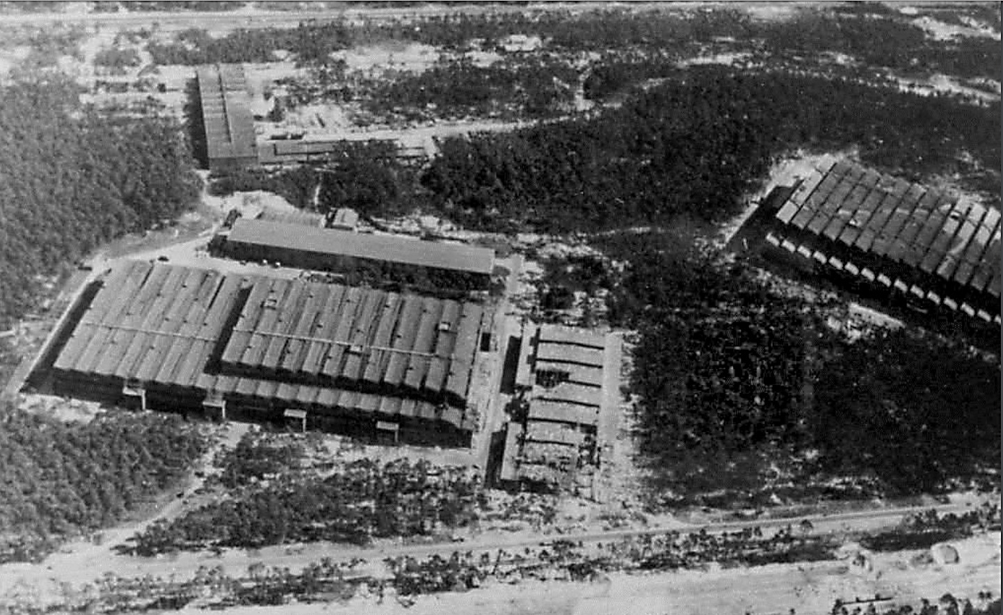
IW and F1 on 19th August 1943
IW and F1 on 19th August 1943
Photo showing Werk Süd with IW on the left and F1 on the right taken on 19th August 1943. The photo shows only light damage to the main halls, although F1 was actually hit at least 11 times, and hits to the separate single storey workshops to the right of the IW hall. The long storage (oil and paint?) shed above IW and the woodworking shop at the top of the picture appear undamaged. Anti-aircraft platforms (at least 3) can be seen on the roof of IW but that seem to be empty of guns. F1 shows two AAA platforms (there was at least 3 at this stage and maybe more) and they may have guns installed. General W. Dornberger mentions defensive AA artillery fire from the from the roof of F1 in his 1952 book V2 (1954 in English).

South Works 23-06-43
South Works 23-06-43
RAF reconnaissance photo showing the Werk Süd region with the F1 pre-production hall and to the north the IW repair and maintenance hall, centre right, and road rail links to Prüfstand XI (Test Stand 11, circular rampart centre left) heading directly left from F1. P-XI was conceived to provide engine test facilities for the nearby pre-production hall. Scroll down to see GPS map, the marker index is set to the centre of P-XI, click map and switch to satellite view and you will see that only a small section of the circular rampart remains visible. You can easily zoom out to cover the coast area where F1 and the equally large Repair & Maintenance Workshops are located. The area immediately surrounding P-XI is now contained within a commercial farming operation with sheep appearing to be the staple – or was anyway, at the time of our first visit to the vicinity in 2010 and our last in 2017 – none of the sheep seemed to recognise us though so they may have changed. (for access to restricted areas click here)
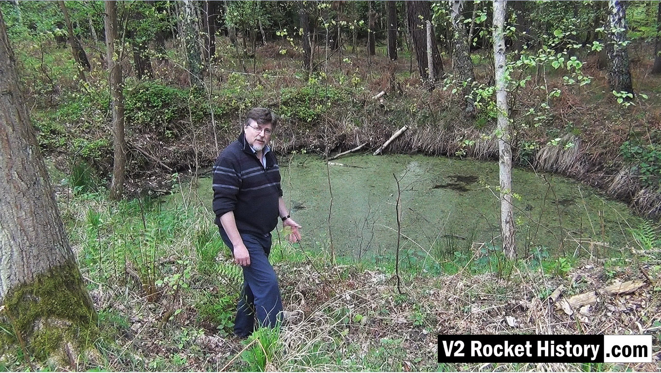
1944 bomb crater near R&MH
1944 bomb crater near R&MH
This video still shows Robert in front of a bomb crater on the West or opposite side of the rail lines and road that pass the Repair & Maintenance Hall (R&MH). The crater like so many others, created in a fraction of a second, in August 1944 during a US air raid, has developed in to a thriving eco-system that now teems with all kinds of life. After the passage of more than 70 years the crater is still deep and well defined. There are hundreds of craters like this in the area.
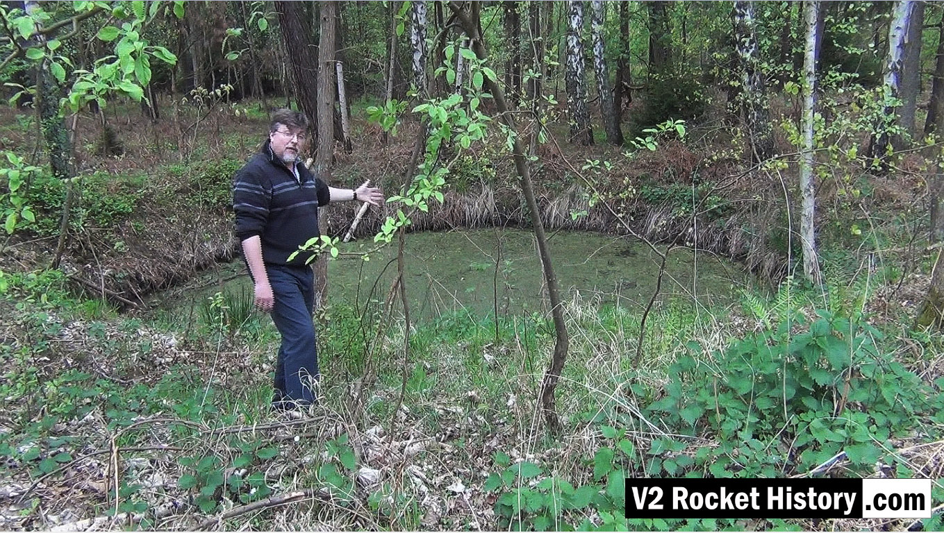
1944 bomb near R&MH – 2nd view
1944 bomb near R&MH – 2nd view
This video still shows the same bomb crater from a slightly different angle. The crater like so many others, created in a fraction of a second in August 1944 during a US air raid, has developed in to a thriving eco-system that now teems with all kinds of life. After the passage of more than 70 years the crater is still deep and well defined. There are hundreds of craters like this in the area.
Ruins of materials storage station No 9 next to F1
Ruins of materials storage station No 9 next to F1
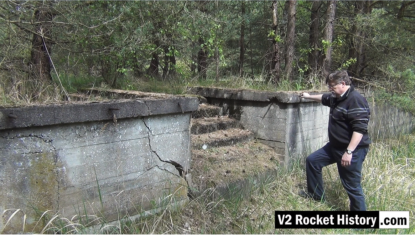
This video screen grab shows Robert about to climb the steps up onto the rail and road loading station 9 (also called Die Verladerampen or in English, The loading ramps). This storage and loading facility was never finished during the war and was intended to be a more elaborate with large storage buildings – but the pressure of war and constant use of the area prevented further development. The area is still surprisingly intact today with a strong correspondence between modern ground detail and historical reconnaissance photography.
Oil storage shed – cut down vertical girder with door hanger
Oil storage shed – cut down vertical girder with door hanger
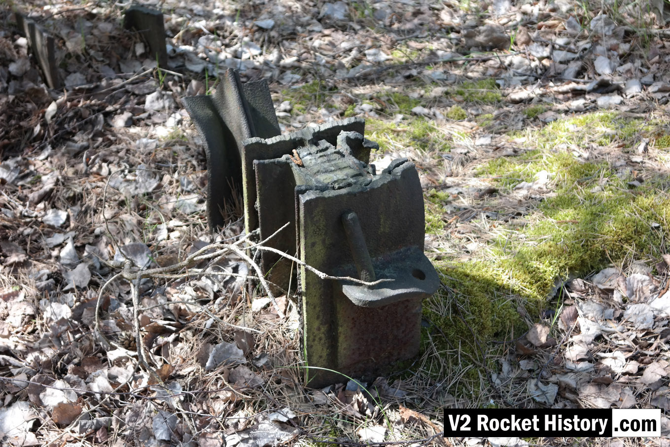
Photo shows the cut stump of an heavy upright support girder. The ragged profile of the cut shows that it has been cut down with an oxygen and gas torch or possibly a larger fuel and oxygen device like a thermal lance. The steel support still has the bottom support pin for a large door. Note that although the girders have been gas-cut there is a great deal of mechanical damage to the steel work that was not caused by the cutting work. Considerable force would be required to bend the middle girder in the way shown, even if it was much longer at the time the bend was created. The upper superstructure of the storage shed may have been part demolished using a bulldozer. Or perhaps the East German Army may have used the site for explosives training – signs of demolition explosive use are in evidence nearby. The map under the album presentation of this picture shows the exact location of the girders.
Missile guidance equipment
Images of guidance and missile control equiment


Missile guidance equipment
Images of guidance and missile control equiment
LEV-3 Horizont and Vertikant gyroscope system 1940
category:Missile guidence, Sub-assemblies


Description
LEV-3 V2 missile gyroscope system with mounting plate. The third component of this system, the Muller gyroscopic accelerometer, is missing – the 2x mounting points can be seen on the right-hand side of the mounting plate.
Location
