

Archives: Gmedia Albums


The Enigmas
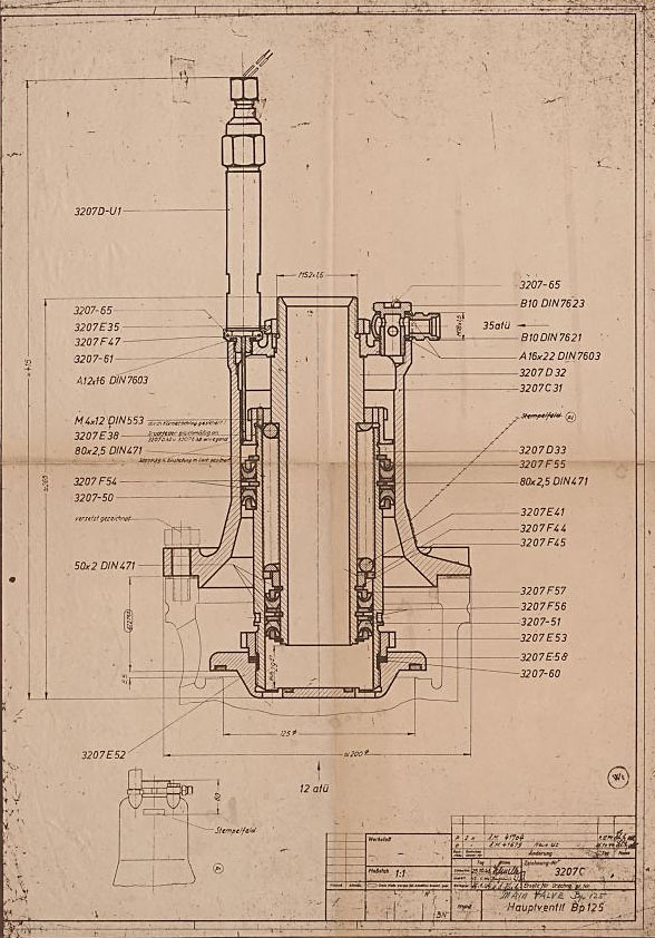
Drawing of Main Fuel Valve 3207C
Drawing of Main Fuel Valve 3207C
Original mpe 1944 drawing number 3207 C of main fuel valave. (mpe = Heimat-Artillerie-Park Karlshagen, Werk Nord Peenemünde).
| Album | Valves |
| Category | Propellant flow |
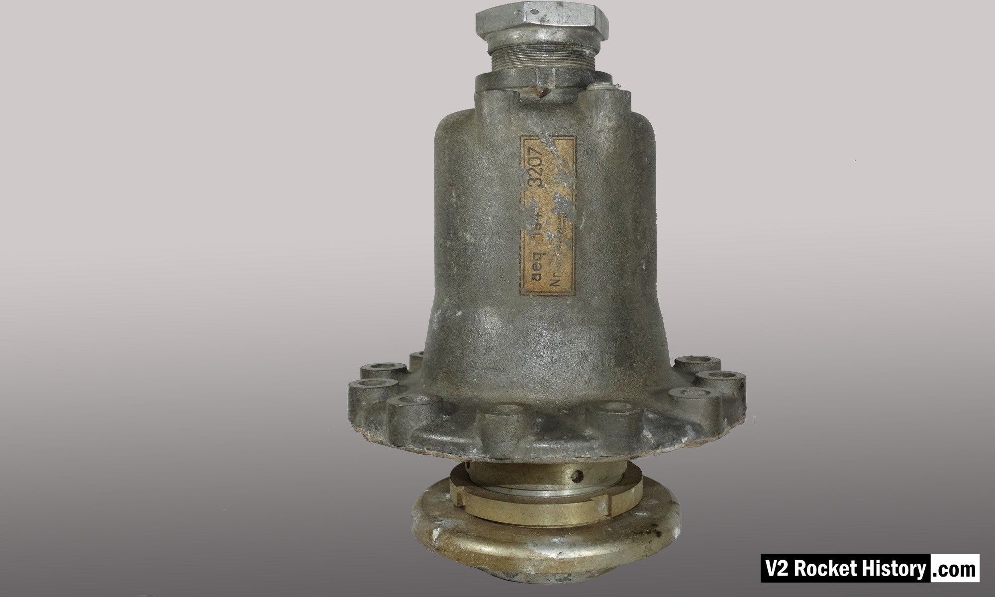
Main Alcohol valve 1
Main Alcohol valve 1
Relic of main alcohol valve with manufacturer code aeq (aeq = Bartoc & Co., Maschinenfabrik u. Giesserei Hedwikow,bei Caslau (Caslav) Czech Republic). An air (nitrogen) inlet pressure of 440 to 530 psi (30 to 36 Bar) was required to close this valve against its internal spring and the force of the turbo-pump. The large nut at the top is the connection for the fuel return (or ‘revolving’line) pipe, and the air and electrical input ports can be seen to the right (air), and left (elec.) just below this point. V2RH image
| Album | Valves |
| Category | Propellant flow |
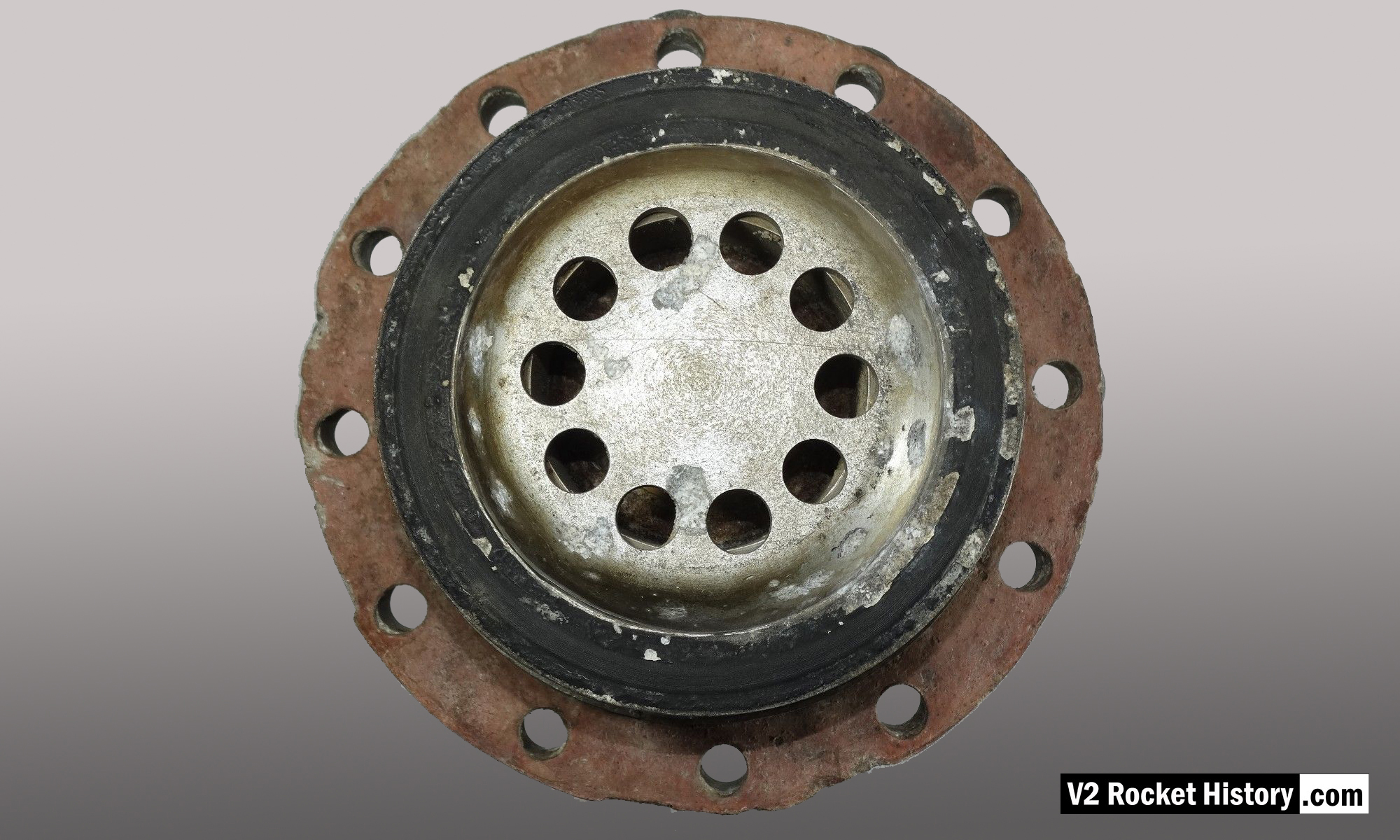
Seat of main alcohol valve
Seat of main alcohol valve
Relic of main alcohol valve showing seat flange and fibre sealing washer. the ten fuel pass-through holes can be seen on the central core of the valve. V2RH image
| Album | Valves |
| Category | Propellant flow |
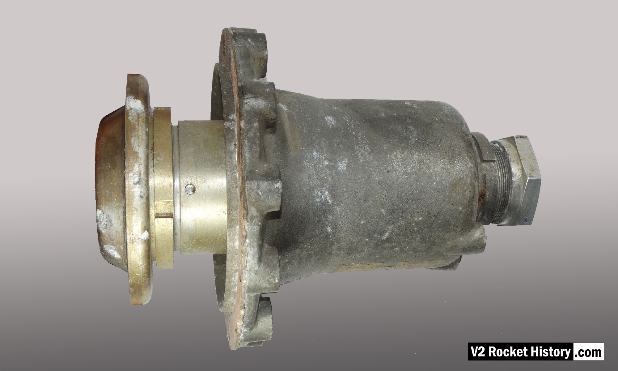
Main Fuel Valve 2
Main Fuel Valve 2
Relic of main alcohol valve with manufacturer code aeq (aeq = Bartoc & Co., Maschinenfabrik u. Giesserei Hedwikow,bei Caslau (Caslav) Czech Republic). An air (nitrogen) inlet pressure of 440 to 530 psi (30 to 36 Bar) was required to close this valve against its internal spring and the force of the turbo-pump. The large nut to the right is the connection for the return (or ‘revolving’line) pipe. The valve is shown in the closed position. V2RH image
| Album | Valves |
| Category | Propellant flow |

Fuel injector flow test results
Fuel injector flow test results
The chart shows water delivery in litres per minute per injector
| Album | Testing fuel injectors |
| Categories | Combustion, Propellant flow |

V2 Rocket standard screw-fit fuel Injector Insert 3304D 1944
V2 Rocket standard screw-fit fuel Injector Insert 3304D 1944
HAP11 drawing of standard 3304D fuel injector screw insert. showing details of primary swirl cavity and orrifice and all additional apertures including the four small cooling pores. HAP11 (Heimat-Artillerie-Park 11, AKA armament code: mpe), drawing number 4554D, Deutsches Museum München

HVP Drawing of diffuser system 1939
HVP Drawing of diffuser system 1939
HVP drawing no 1203D showing burner cup ‘diffuser system’ disposition for 19-pot head (at this stage the 25 ton thrust injector head had nineteen so called ‘pre-chambers’ or pots as no central fuel valve was present). HVP drawing dated 1939.

Drawing of fuel nozzle Insert 1113E 1939
Drawing of fuel nozzle Insert 1113E 1939
Drawing from the Army Experimental Station Peenemünde dated 1939. The specification describes an insert template that could be used for a range of outlet and inlet orifice sizes. The German text beginning (eingedrehte …) translates as ‘Center-line of screw used for holes to be drilled later’, and the hole dimensions are not specified on this document. HVP drawing number 1113 E, Deutsches Museum München

Standard V2 Rocket fuel Injector Inserts
Standard V2 Rocket fuel Injector Inserts
Diagram showing cut-away presentations of the settled configuration of standard four ‘swirl’ inserts used in the V2 rocket engine’s 18-pot head from 1943 until the end of the war. The inserts are shown with their drawing code identification. All of the insert types used in the injector head are shown, however there were additional screw-in type fuel supply inserts, used to provide a fuel cooling balance function, located radially in the lower part of the combustion cavity.

Test Rig With E Type Insert
Test Rig With E Type Insert
Single nozzle insert test rig used by V2 Rocket History to test spray shape and volume at fluid supply pressures consistent with fuel pressures specified for the injector head of summer 1944. A 2131E fuel injector insert is installed in the holder at the front of the test rig, but as the thread was the same on all inserts the nozzle can be changed for other models easily with aid of a pin spanner. See video for a demonstration of this simple test system.

V2 fuel injector Insert test rig
V2 fuel injector Insert test rig
Single nozzle insert test rig used by V2 Rocket History to test spray shape and volume at supply pressures consistent with fuel pressures specified for the injector head of summer 1944. The test system features an adjustable pressure regulator and fluid pressure gauge. For test purposes the device was simply connected to a relatively high pressure mains water supply. And although water does not have the same viscosity of the 75% Ethenol to 25% water mix of the V2’s fuel it was considered close enough by the German technicians, who regularly used plain water as a substitute when testing issues related to furl flow rather than combustion. A 2131E fuel injector insert is shown installed in the holder at the front of the rig, but as the thread was the same on all inserts the nozzle can be changed for other models easily with aid of a pin spanner. See video for a demonstration of this simple test system.
General view drawing V2 rocket Turbo Pump 1942
General view drawing V2 rocket Turbo Pump 1942
Sectioned general assembly view of the V2 turbo-pump (TP) dated September 1942. This image has been edited to show TP and document data closer together than the original.
Relics of the ‘Standard’ series A aluminium head c. 1941
Relics of the ‘Standard’ series A aluminium head c. 1941
Relics of the A4 25-ton 1941 aluminium injector head. See other photos in this series for more detail. Photo courtesy Horst Beck Collection
Part of the ‘Standard’ series A aluminium head from 1941/42
Part of the ‘Standard’ series A aluminium head from 1941/42
Part of the ‘Standard’ series A aluminium head from 1941 to early 1942. Showing the position of standard type LOX injector. The brass fuel injector inserts type and position pattern on the relic seem to be of the standard type with the row of 3 inlet aperture type inserts positioned furthest from the LOX injector. Photo courtesy Horst Beck Collection
Flown V2 combustion injector head relic from 1945
Flown V2 combustion injector head relic from 1945
Injector head relic from February 1945 showing injector insert type and pattern. Photo www.v2rockethistory.com
A4-V2 primary missile valves
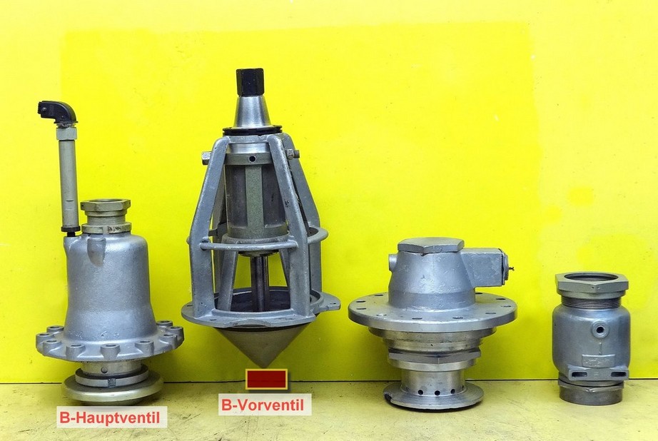
A4-V2 primary missile valves
This photo shows a presentation of important vales from the A4-V2 missile. From the left: Main alcohol/B stoff valve (from the centre of injector head. Alcohol tank valve. Main LOX valve (with sub valve). Alcohol (B stoff) tank pressuring valve. Image courtesy Horst Beck Collection
| Album | Valves |
| Category | Propellant flow |
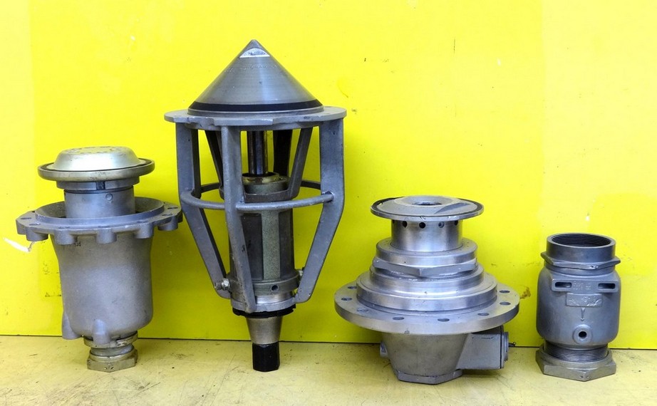
V2 engine main propellent valves, 2nd view
V2 engine main propellent valves, 2nd view
Photo shows main valves. Photo copyright: The Horst Beck Collection
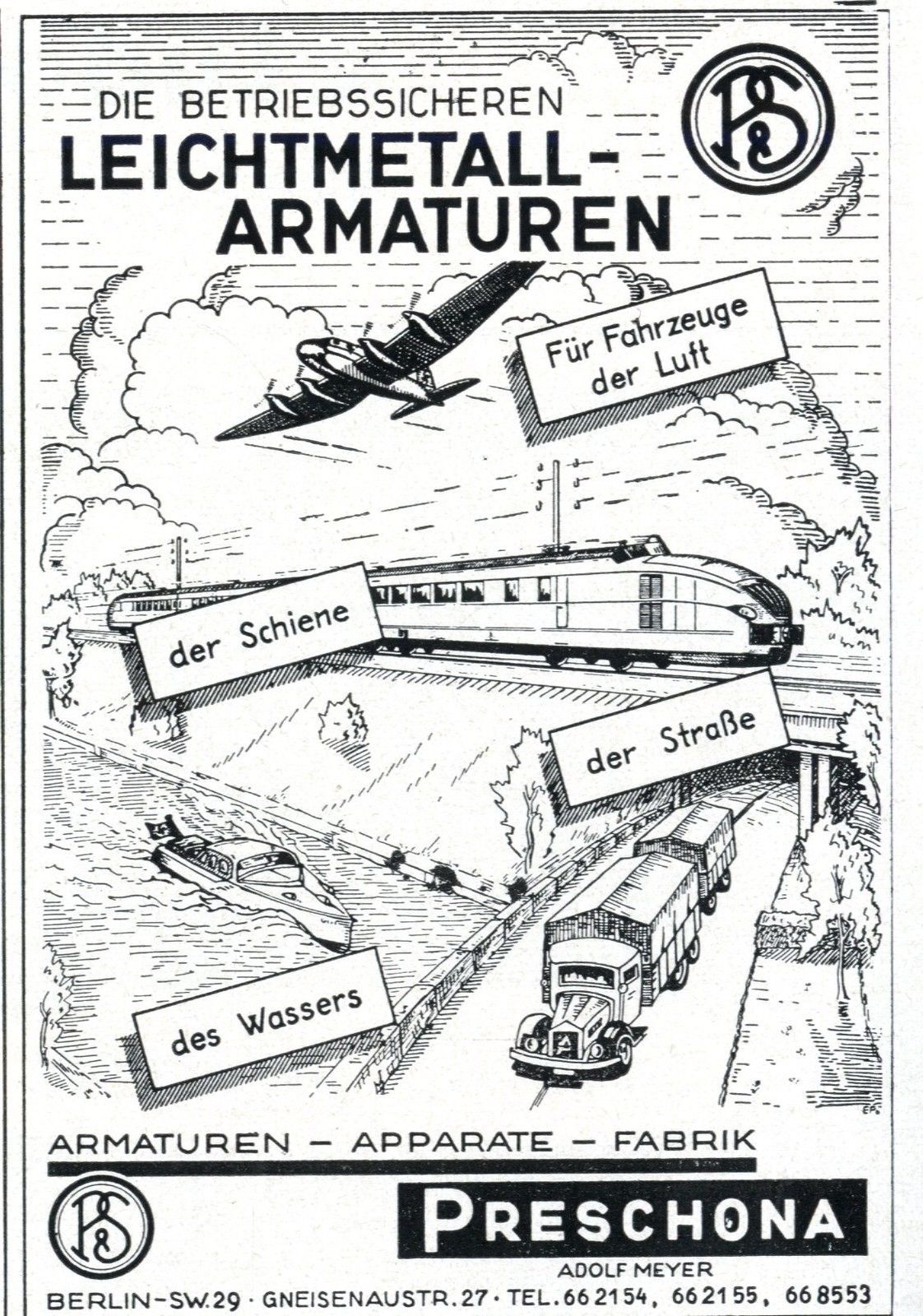
Preschona trade advert
Preschona trade advert
Trade literature advert for the Preschona company (Adolf Meyer) in Berlin, Germany. The company was a supply contractor and (among other items) manufactured the non-return valve for the steam turbine exhaust heat exchanger, employed to volatilise a small portion of liquid oxygen (LOX) to pressurise the LOX tank to maintain critical flow volume to the LOX turbo-pump.
F1: Fertigungshalle Eins

Karlshagen West, railway sheds ruins
Karlshagen West, railway sheds ruins
This picture shows some of the extensive ruins that were once part of the railway shed complex West of the railway lines heading to the Development Works. Screen grab from Karlshagen video.
| Album | Karlshagen |
| Category | Peenemünde-Usedom-locations |
Equipment bays
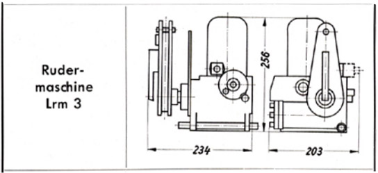
Askania rudder servo ‘Rudermaschine LRM 3’
Askania rudder servo ‘Rudermaschine LRM 3’
A schematic drawing of the Askania rudder servo ‘Rudermaschine LRM 3’showing the critical compact dimentions of the device making it ideal for retro fit projects for smaller aircraft.
Control compartments 1 & 4
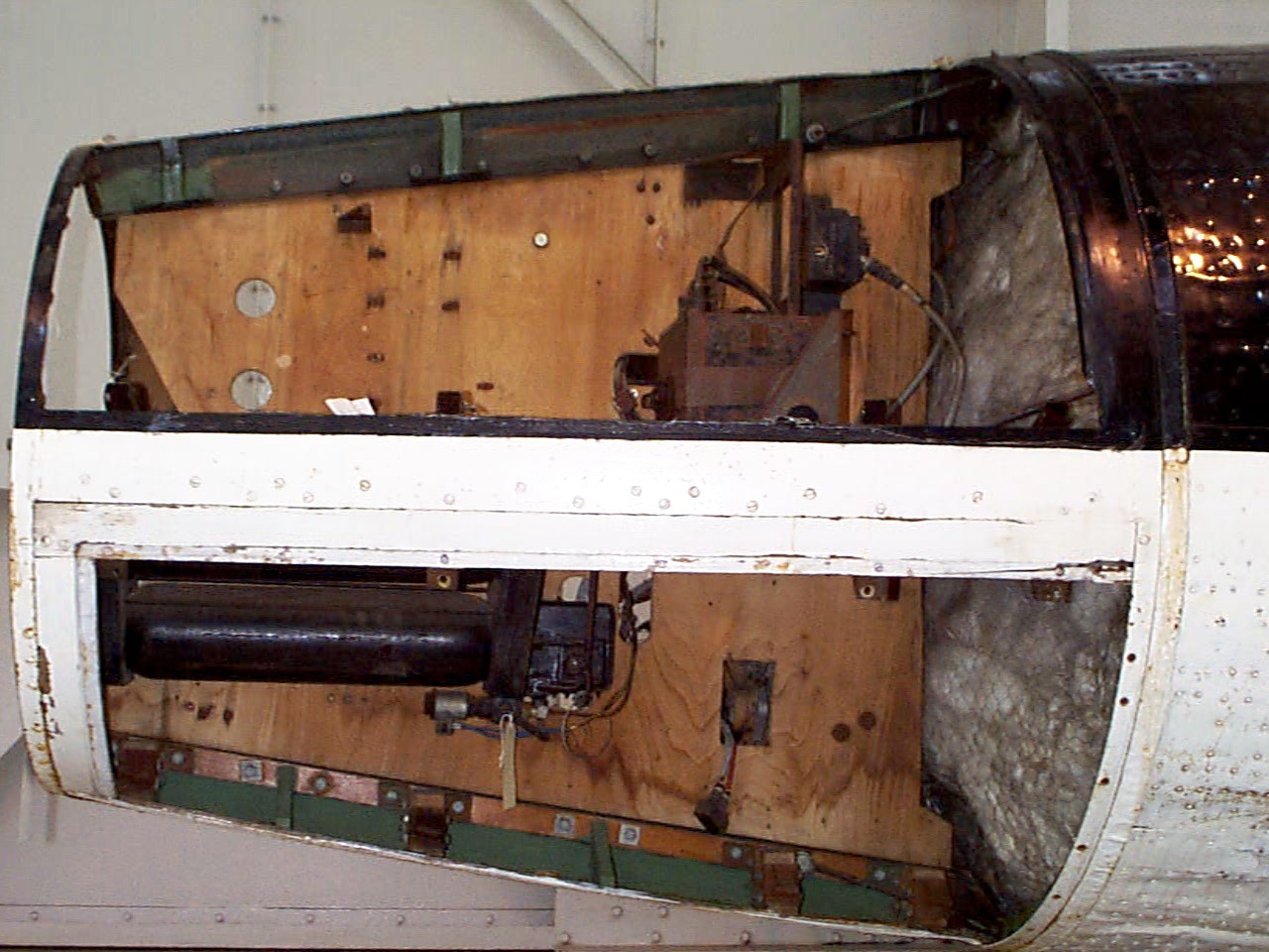
Control compartments 1 & 4
Control compartments 1 (upper) & 4 (lower) Image copyright Imperial War Museum
| Album | Equipment bays |
| Category | Missile guidence |

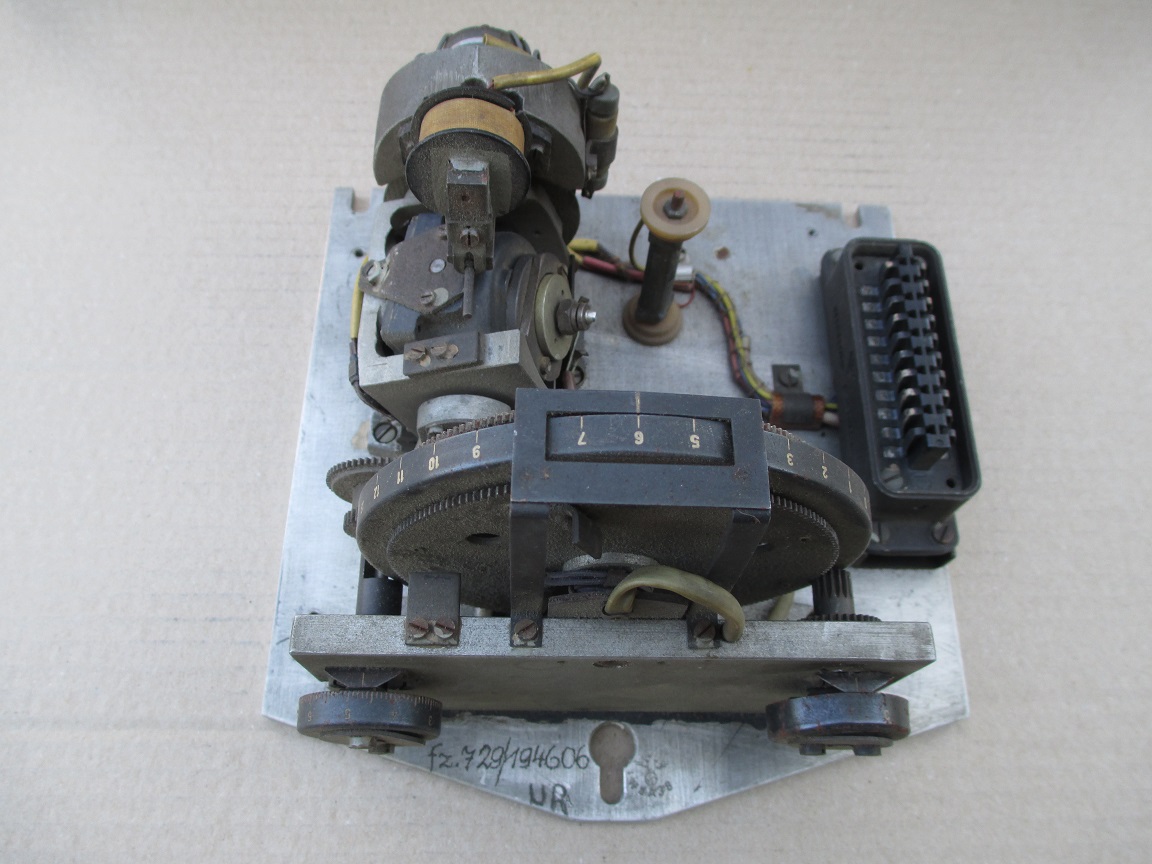
LEV-3 Horizont and Vertikant gyroscope system 1940
LEV-3 Horizont and Vertikant gyroscope system 1940
LEV-3 V2 missile gyroscope system with mounting plate. The third component of this system, the Muller gyroscopic accelerometer, is missing – the 2x mounting points can be seen on the right-hand side of the mounting plate.
| Album | Missile guidance equipment |
| Categories | Missile guidence, Sub-assemblies |

Remains of 36 volt battery cells used on the V2 to power onboard equipment. ©THBC
Remains of 36 volt battery cells used on the V2 to power onboard equipment. ©THBC
Photo shows rare surviving complete set of 8 lead acid battery cells from one of the V2 rocket’s 32 volt (100 amp) lead acid batteries. Two sets of batteries like this were used to provide the direct current (DC) voltage used aboard the V2 missile to power the DC to 3-phase alternating current (AC) generators, that in turn, powered the gyroscopes, electro-hydraulic servos, trim motors and other vital guidance and control devices. Photo copyright: The Horst Beck Collection
A4-V2 control surface servo and trim motors. ©THBC
A4-V2 control surface servo and trim motors. ©THBC
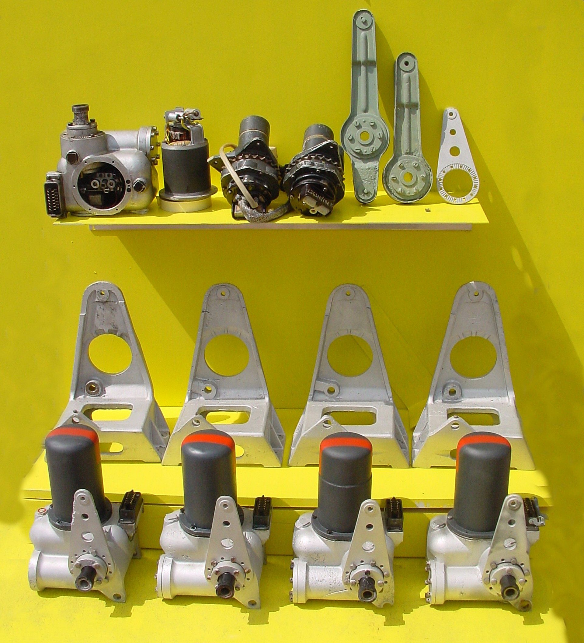
Photo shows a unique display at the Horst Beck Collection (HBC). Over many years Mr Horst Beck has painstakingly acquired and restored many A4-V2 missile parts – and in some cases, reassembled them into complete sub-assemblies. Shown here is part of the collection’s hydraulic servos and trim motor parts display. In the foreground we see four hydraulic servos, and behind them their A frame mounting ‘chairs’. The top shelf, from left to right, shows a servo with motor removed (and placed on its right). In the middle, two trim motors and chain sprocket gear-boxes for the aerodynamic trim surfaces on the trailing edge tips of fins 2 and 4. Next the pale green crank levers, the first longer one is for the hydraulic servo that controls the jet vanes and trimmers on fins 1 and 3. The shorter version minus the top horn, is used on the servos for fins 2 and 4. The last, silver coloured item,os a servo stabiliser (all the servos shown have one already fitted). Photo copyright: The Horst Beck Collection
A4-V2 air rudder detail. ©THBC
A4-V2 air rudder detail. ©THBC
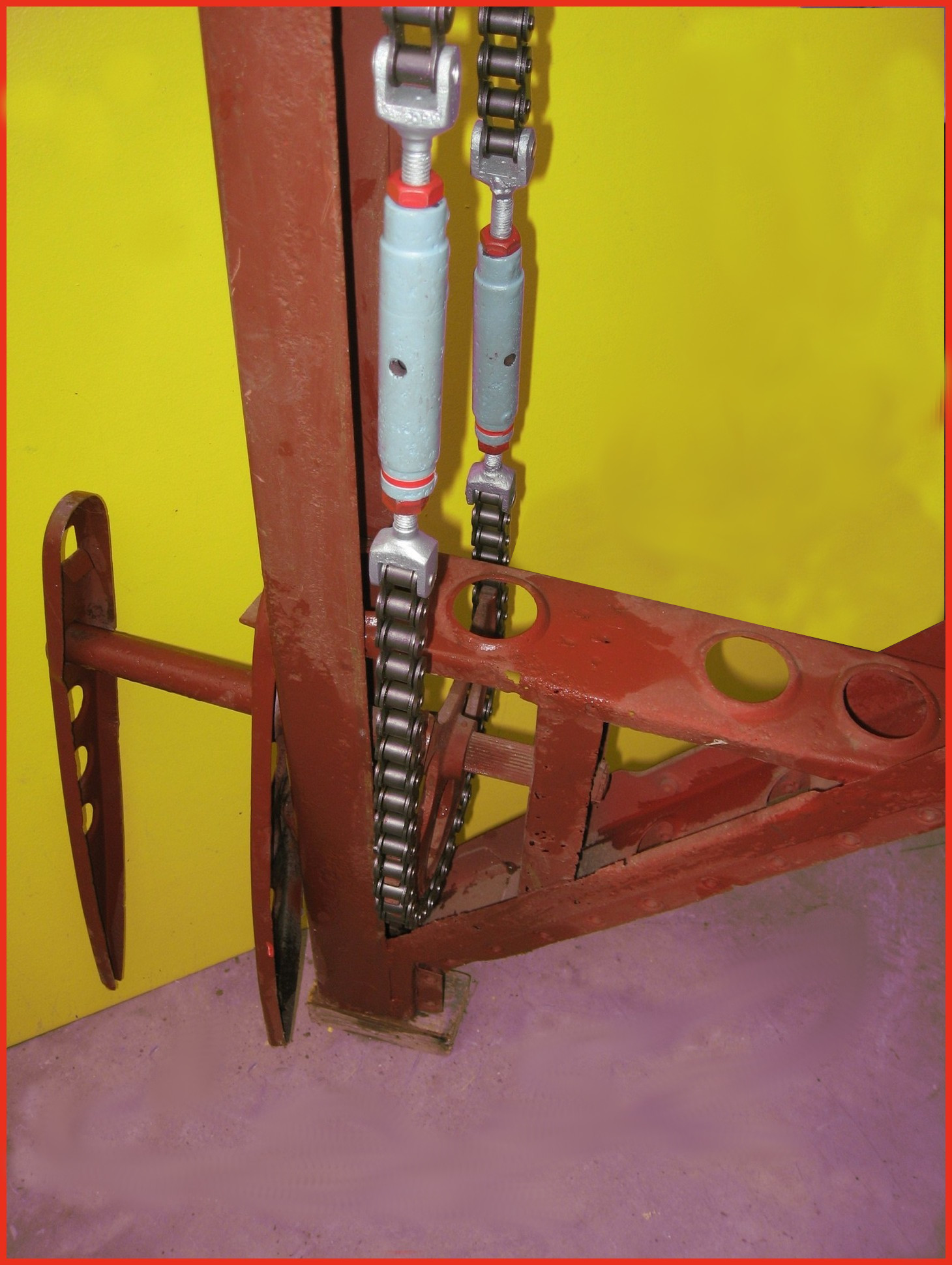
Photo shows restored air-rudder and fin detail. The grey painted barrel-strainers are both adjusted independently to reduce slack in the drive chain and avoid introducing a deflection bias in the air rudder. The 1.9kg counterbalance weight normally located at the top of the trim fin (or air rudder) is missing in this presentation. This excellent restoration is the work of Horst Beck. Photo copyright: The Horst Beck Collection
Detail of fin 2 or 4 showing trim motor and drive chain
Detail of fin 2 or 4 showing trim motor and drive chain
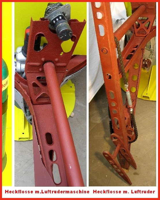
Photo shows partially restored air-rudder and fin detail. The image on the left shows the relationship of the trim motor to the air rudder drive shaft on fins 2 and 4. A chain similar in gauge to the type used on a push-bike and yet, at the other end of the shaft, the chain transmitting the torque of the trim motor to the air-rudder drive sprocket has a heavy gauge chain similar to that found on a 1000CC motor-cycle! This excellent restoration is the work of Horst Beck. Photo copyright: The Horst Beck Collection

Restored graphite vane thrust ring support housings. ©THBC
Restored graphite vane thrust ring support housings. ©THBC
Photo shows four restored graphite jet vane support blocks and bearing housings. The round plates we can see here act as heat sinks and allow heat to radiate away from the support block and bearing to help prevent expansion due to relatively rapid and uneven temperature distribution accumulation. The graphite vanes were quite brittle and cracking caused by rapid and uneven expansion could cause the vane to disintegrate. The area around the graphite vanes was exposed to the accumulation of heat not merely as a result of duration of the motor burn time but temperature was also increased at higher rates as the jet plume expanded with the decreasing atmospheric pressure as the missile gained altitude. This excellent restoration is the work of Horst Beck. Photo copyright: The Horst Beck Collection

A4-V2 50 volt command or signalling battery. ©THBC
A4-V2 50 volt command or signalling battery. ©THBC
Photo shows rare surviving 1.2 volt cell from the V2 missile’s 50 volt command or signalling battery used in its gyro guidance system (note, the terminal connection on the left is missing from this exhibit, it would be identical to the one on the right). This wet nickel-cadmium battery cell was combined in pairs to a total set of 21 providing a 50.4 voltage at 300mA. The cells were contained in a wooden box that was held on a rack in equipment bay III. Its function was to provide the direct current (DC) signalling voltage that communicated the moment to moment resistance of the gyroscope’s potentiometers to the analog guidance computer (Mischgerät = Mixer-device or control amplifier) aboard the V2 missile. It was critical that the signalling voltage was maintained between 48 and 50.4 volts. Photo copyright: The Horst Beck Collection

Impact wreckage of electro-hydraulic jet vane servo
Impact wreckage of electro-hydraulic jet vane servo
Wreckage of hydraulic servo from fin 2 or 4 of V2 missile that fell on a farm in Essex in March 1945. The motor has been removed and we can see details of the oil gear pump and valve control gear. The 3 position electromagnetic relay switch is visible at the 7 to 8 o’clock position within the open aperture. The push rod that connects the relay to the gear pump valves is also visible as a short brown coloured rod with a fine wire connector at each end, running in towards the gear-valves from the 9 o’clock position. The point that provides electrical current for the motor (which runs all the time and in one direction only) can be seen at the three o’clock position. The black housing has two sets of brass tongues that receive the matching brass spades mounted on the base of the motor for power input. The motor drive shaft has a female square socket coupling to connect the motor to the middle drive gear of the gear pump. A small portion of the square drive shaft of the central gear can just be seen in the photo – in the centre of the valve control block.

Muller Mechanical Integrating Gyroscopic Accelerometer
Muller Mechanical Integrating Gyroscopic Accelerometer
The Muller mechanical or Pendulous Integrating Gyroscopic Accelerometer – today normally referred to as a PIGA. Designed by Fritz K Muller.
The J device, no1 (J Gerate Eins) or Muller Mechanical Integrating Accelorometer. © THBC
The J device, no1 (J Gerate Eins) or Muller Mechanical Integrating Accelorometer. © THBC
The J device no1 (J Gerate Eins). The full name of this device is: the Muller Pendulous (or mechanical) Integrating Gyroscopic Accelerometer – today normally referred to as a PIGA. The device, designed by Fritz K Muller, operates as a switch to initiate rocket engine shutdown and is able to smoothly record and accumulate every moment of acceleration, without any kind of recording resolution or discrete time interval limit, of the rocket’s entire motor burn phase, and at the same time process this accumulated acceleration with respect to time as a gradually increasing velocity. In the case of the V2 missile, when the correct predetermined velocity is reached, the velicity sufficient to achieve the desired range of the missile, the device trips the relays that close valves that shutdown the supply of steam to the turbo-pump, and thus shutdown the rocket motor itself.

Hydraulic servo impact debris
Hydraulic servo impact debris
Hydraulic servo from fin 1 or 3 of the V2 missile, collected with other debris following a combat impact.
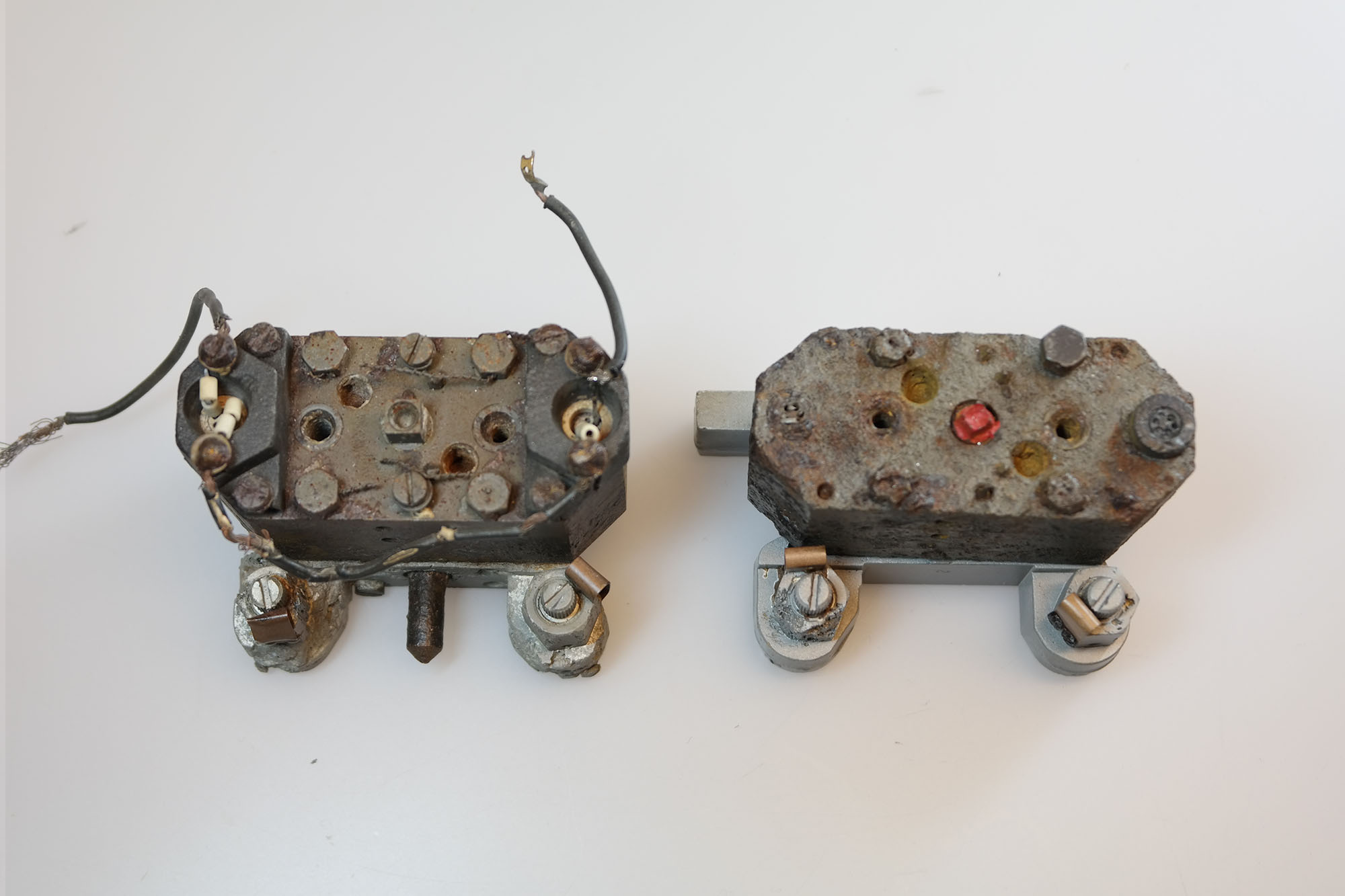
Fin and jet vane servo: Hydraulic gear pumps
Fin and jet vane servo: Hydraulic gear pumps
Two Askania (designed) hydraulic gear pumps – the examples shown here have two ceramic insulators with with Nichrome wire type heating elements. The heaters are located at each end of the pump on the long axis. The pump on the right still has its power supply wires attached and was easily repaired and restored to full function in our workshop.This type of pump (with heaters) seem to be rare among the debris of European combat impact sites but fairly common in debris collections emanating from research flights in Peenemünde and parts of Poland. An explanation maybe that the oil could be warmed up sufficiently simply by starting all four hydraulic gear pumps sooner in the pre-launch sequence. The only downside being that the already noisey missile would be making yet more noise in the risky period leading up to launch.
Missile guidance equipment
Images of guidance and missile control equiment


Missile guidance equipment
Images of guidance and missile control equiment
LEV-3 Horizont and Vertikant gyroscope system 1940
category:Missile guidence, Sub-assemblies


Description
LEV-3 V2 missile gyroscope system with mounting plate. The third component of this system, the Muller gyroscopic accelerometer, is missing – the 2x mounting points can be seen on the right-hand side of the mounting plate.
Location
