

Archives: Gmedia Albums


The Enigmas
Unknown repair workshop (IW) mechanism
Unknown repair workshop (IW) mechanism
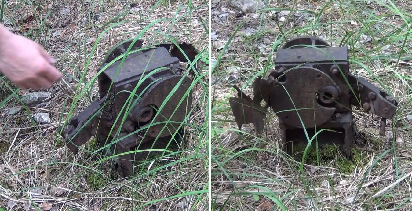
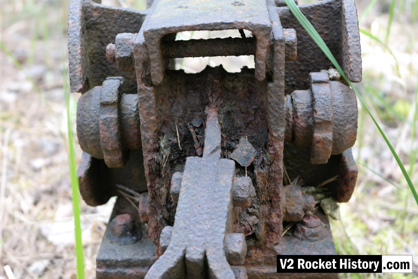
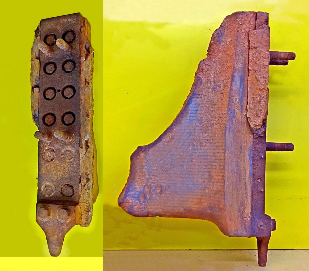
We think this relic, welded to a heavy gauge H beam, may be a points switch for a railway line. But do you know what it is, and what it did? If you do, please tell us.
| Album | The Enigmas |
| Category | Mystery part |
Unknown helical part
Unknown helical part
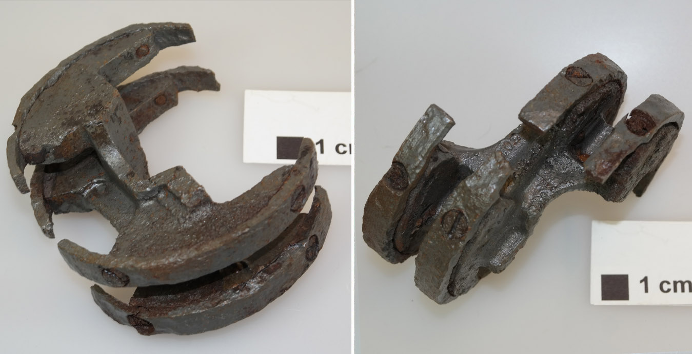
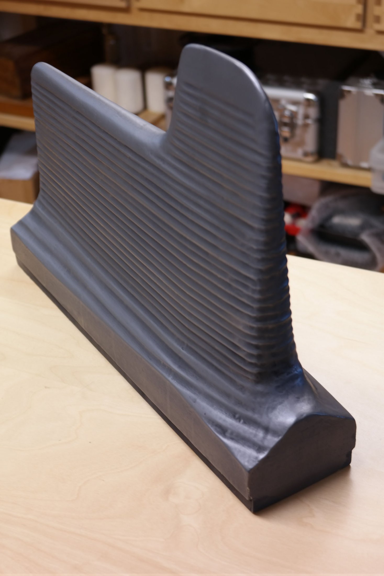
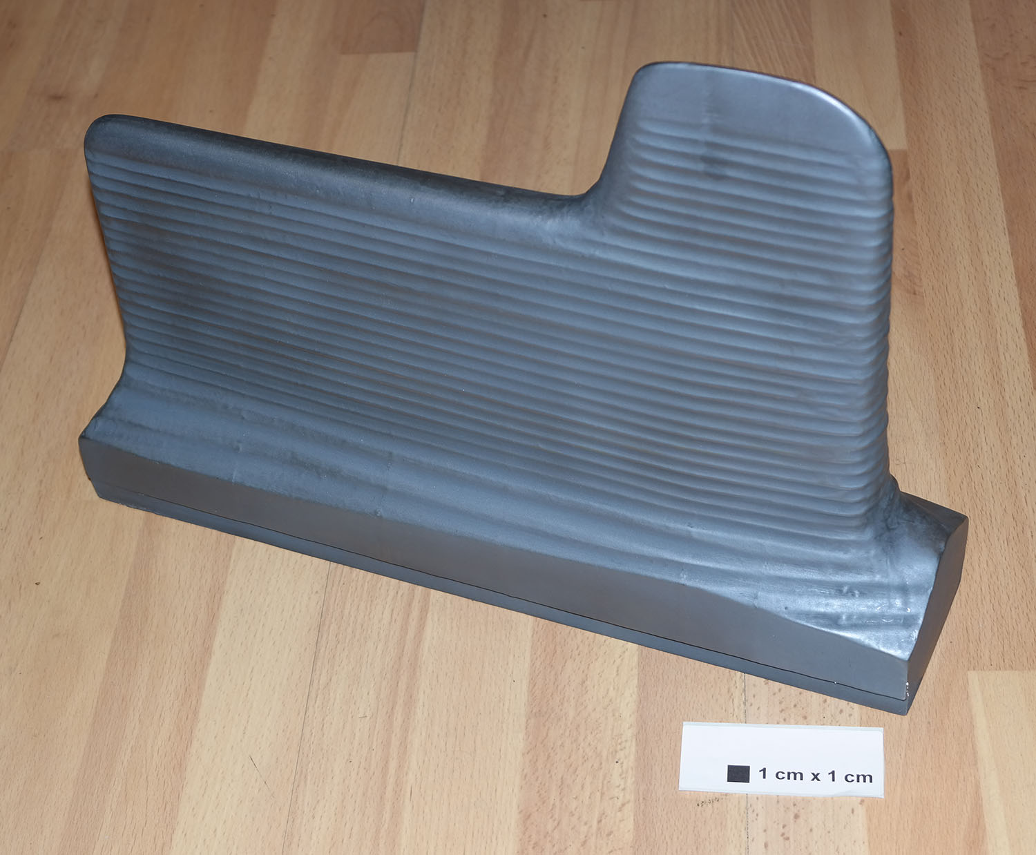
This part has a helicoid or screw shape, it seems that it might have been designed to screw into a pipe of some kind. But do you know what it really is, and what it did? If you do, please tell us.
| Album | The Enigmas |
| Category | Mystery part |
Chain and hook clamp – unknown use
Chain and hook clamp – unknown use
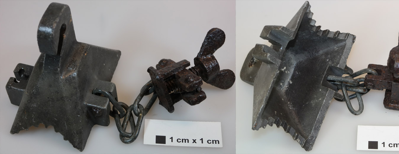
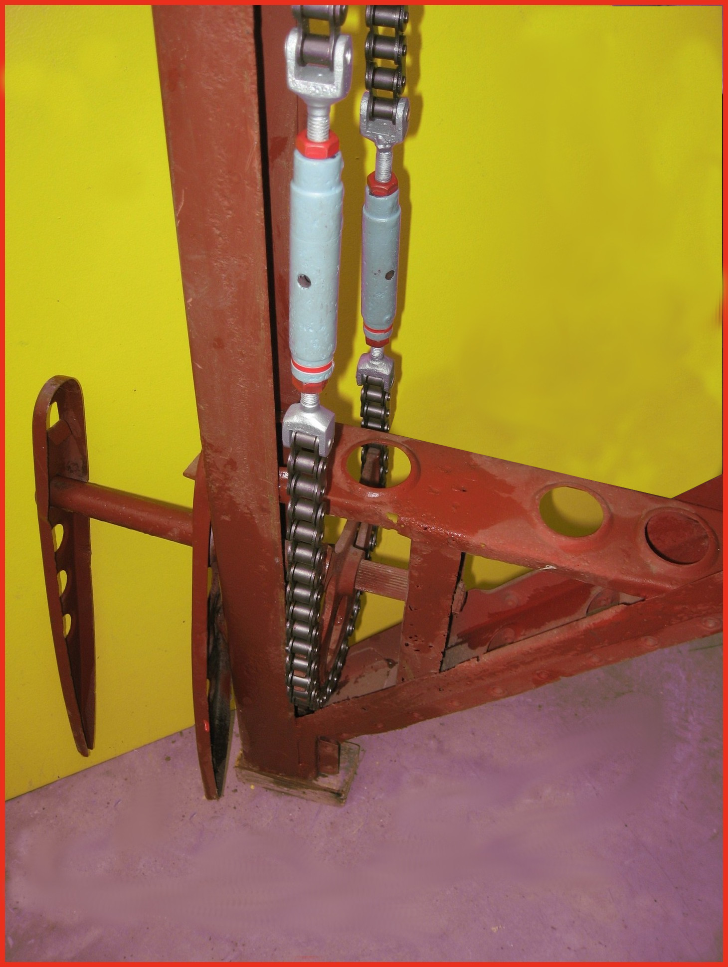
We know this is a clampy-chainy-hooky thing – but do you know what it really is, and what it did? If you do, please tell us.
| Album | The Enigmas |
| Category | Mystery part |
Close up of relic within IW near aisle 20
Close up of relic within IW near aisle 20
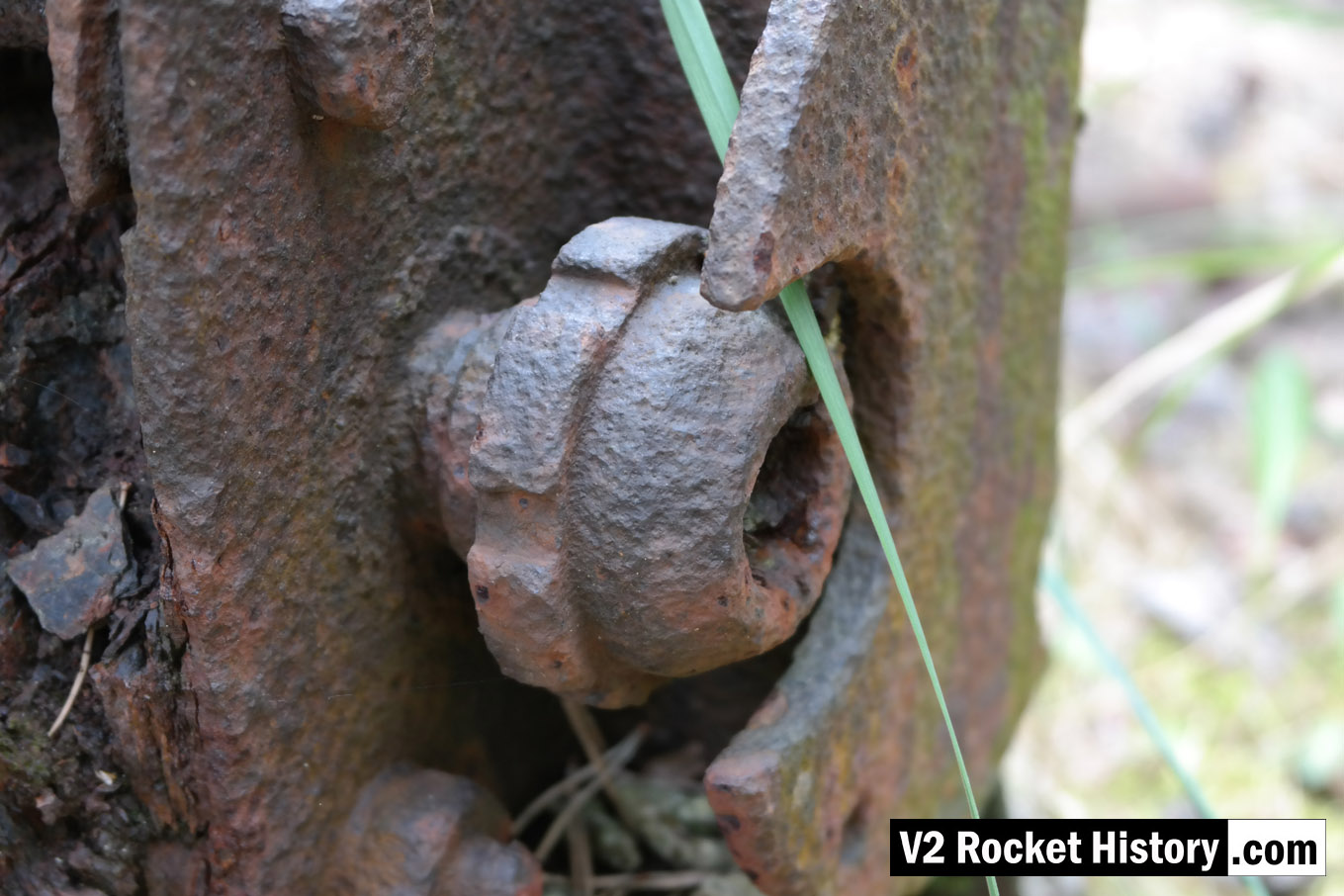
This is a close up of the mystery item, referred to on our Enigma page, found firmly anchored to the floor a few metres inside the east wall near aisle 20 of IW (near location of internal railway line).
| Album | The Enigmas |
| Category | Mystery part |
Close up of relic within IW near aisle 20
Close up of relic within IW near aisle 20
This is another close up of the mystery item showing the mechanism in more detail. It can be found firmly anchored to the floor a few metres inside the east wall near aisle 20 of IW (near location of internal railway line). See map below for location.
| Album | The Enigmas |
| Category | Mystery part |
F1: Fertigungshalle Eins
Unknown repair workshop (IW) mechanism
Unknown repair workshop (IW) mechanism
We think this relic, welded to a heavy gauge H beam, may be a points switch for a railway line. But do you know what it is, and what it did? If you do, please tell us.
| Album | The Enigmas |
| Category | Mystery part |
IW and F1 on 19th August 1943
IW and F1 on 19th August 1943
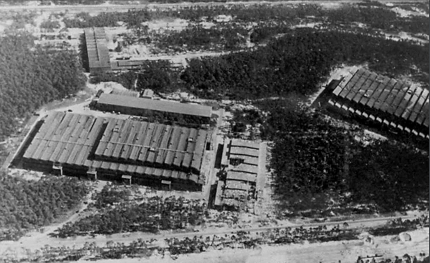
Photo showing Werk Süd with IW on the left and F1 on the right taken on 19th August 1943. The photo shows only light damage to the main halls, although F1 was actually hit at least 11 times, and hits to the separate single storey workshops to the right of the IW hall. The long storage (oil and paint?) shed above IW and the woodworking shop at the top of the picture appear undamaged. Anti-aircraft platforms (at least 3) can be seen on the roof of IW but that seem to be empty of guns. F1 shows two AAA platforms (there was at least 3 at this stage and maybe more) and they may have guns installed. General W. Dornberger mentions defensive AA artillery fire from the from the roof of F1 in his 1952 book V2 (1954 in English).
RAF Recce photo taken 21st August 1944 of region around F1
RAF Recce photo taken 21st August 1944 of region around F1
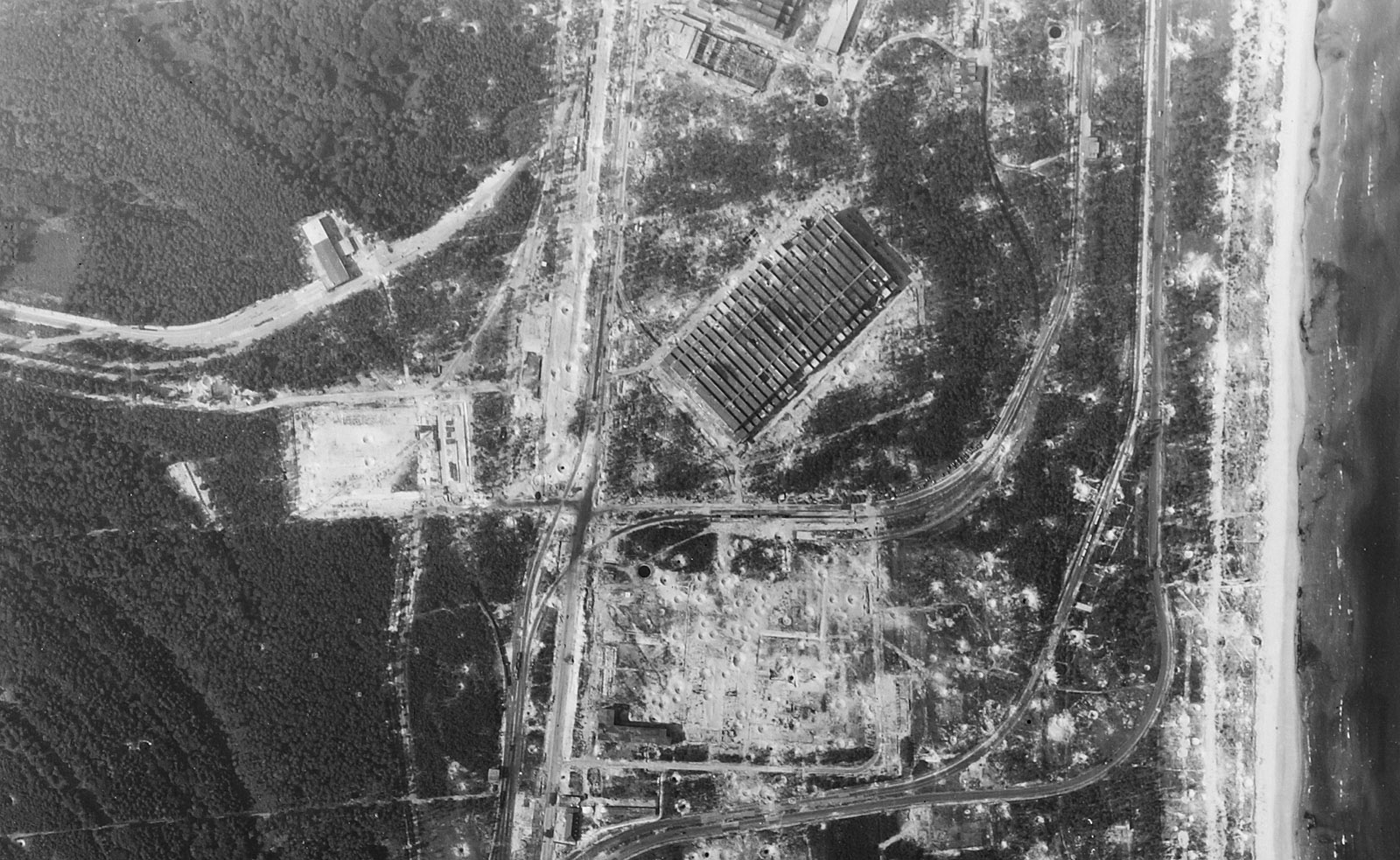
RAF Recce photo taken 21st August 1944 of region around F1. The GPS marker for this photo is pegged on the lowest of the three fire fighting cisterns clearly visible in the image (in the center about a third the way up from the bottom of the image). Scroll down below this text for map and switch to ‘Satellite view’ where the fire fighting cistern can still be clearly seen today.(for access to restricted areas click here)
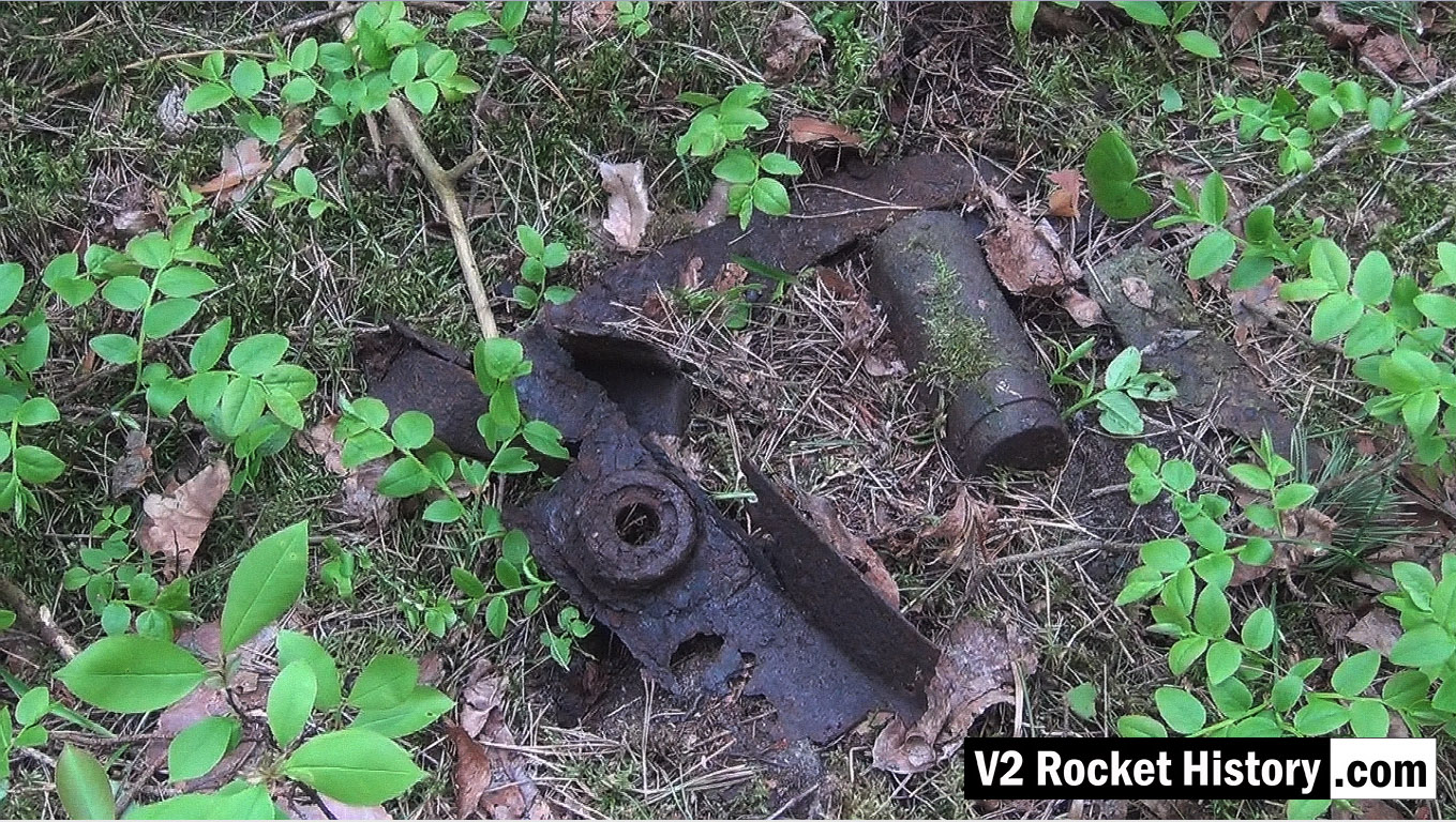
V2 fin relic near F1
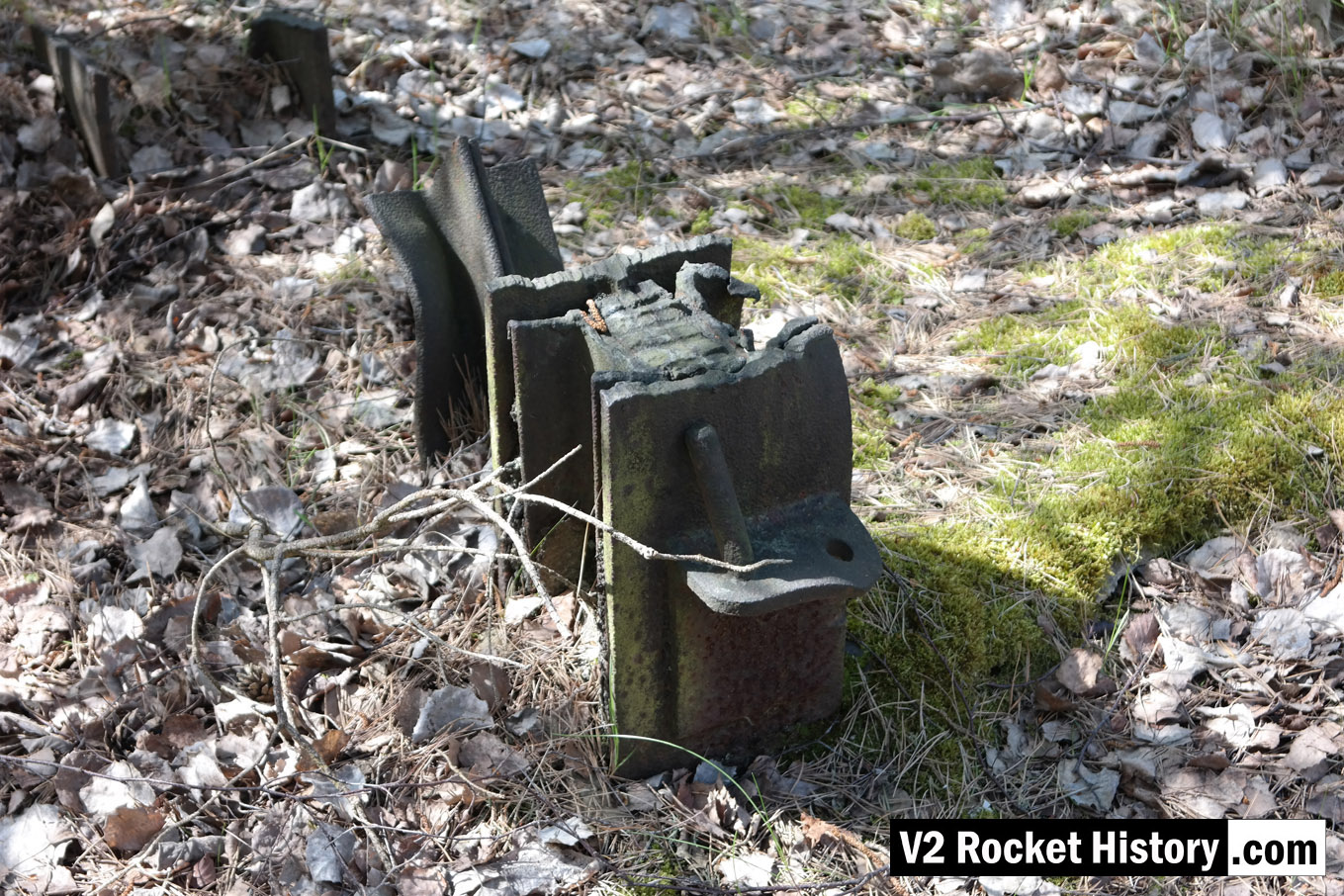
V2 fin relic near F1
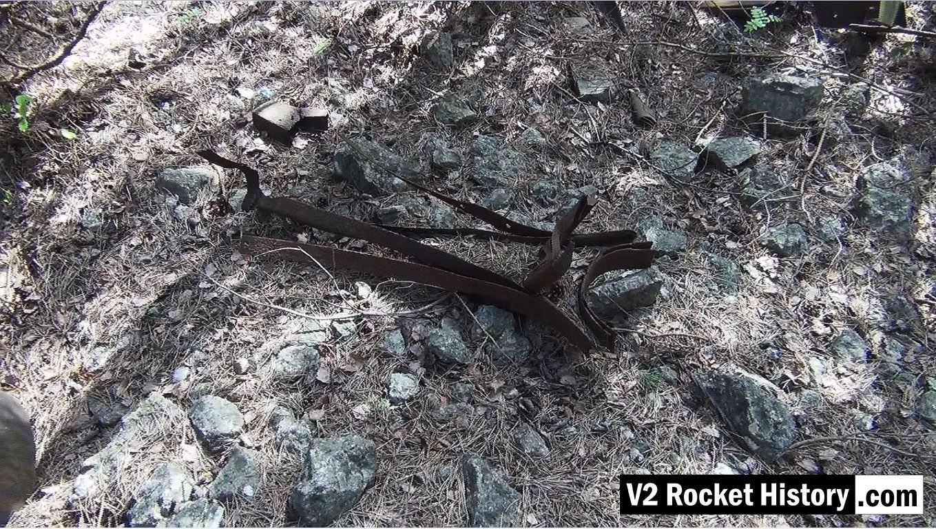
Picture shows parts of V2 missile fin structure laying on open ground near area between admin offices and F1 (near Admin. block railway platform, see map).
Storage vessel within F1 boundary
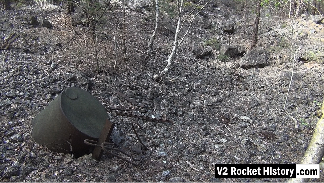
Storage vessel within F1 boundary
Picture shows metal debris within the F1 factory boundary walls. The purpose of the part buried liquid storage vessel in the foreground is unknown but it is not a vessel capable of being pressurised. Other assorted metal debris include pipe and cable wall cleats, as well as steel armature rods from reinforced concrete castings (powerful demolition explosions have freed the steel rods from the concrete). These reinforcement rods are a common sight in the environs of Fertigungshalle Eins (F1) and the nearby Repair & Maintenance Hall (R&MH).
V2 missile debris field SE of F1
V2 missile debris field SE of F1
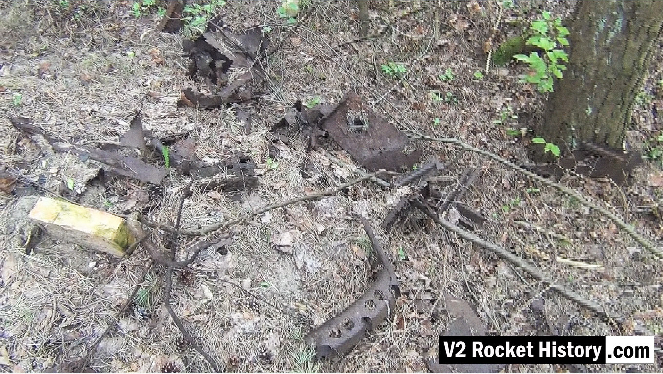
This picture shows a small debris field of steel fragments from the V2 missile 130m South-East of F1, and just 20m to the North East of the foundations of a small heat distribution building. Various body and frame parts can be seen and in the middle foreground a 350mm segment of curved missile body ring is visible. These parts have almost certainly been dug up and exposed by the action of metal detectorists. The metal fragments have been abandoned by their finders as they are perceived to have no financial value and hence are not worth removing from the site.
V2 missile debris near F1
V2 missile debris near F1
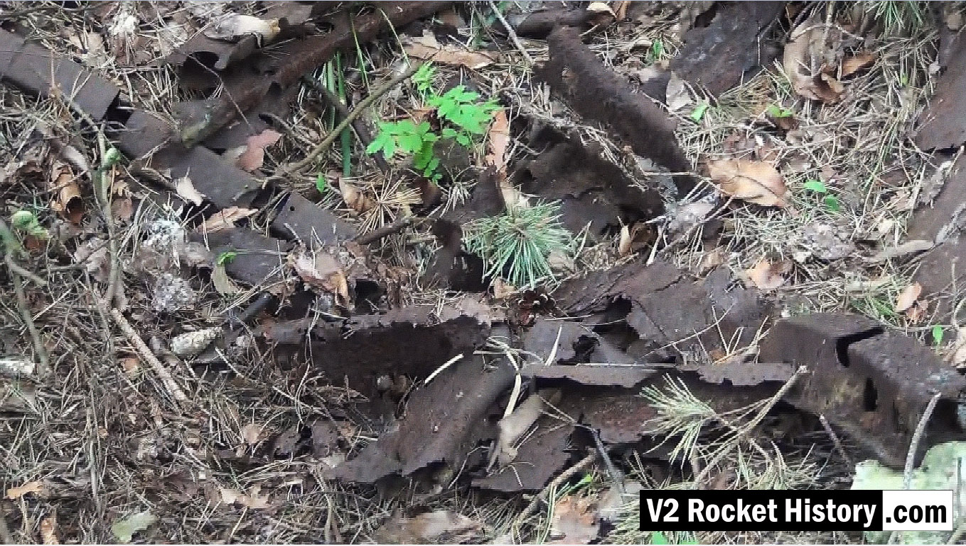
This picture shows a close up detail of parts in a small debris field of steel fragments from the V2 missile 130m South-East of F1, and just 20m to the North East of the foundations of a small heat distribution building. Various body and frame parts can be seen and in the upper left and two segments of curved missile body ring are visible. See previous.
Wooden Carboy frame
Wooden Carboy frame
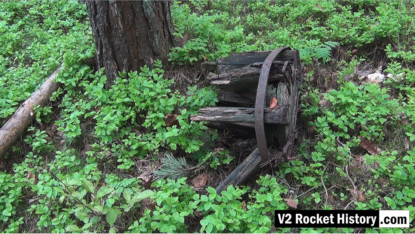
Wooden carboy frame from WW2 (possibly used for transporting small quantities of corrosive and dangerous liquids employed in the V2 steam plant, (such as T-Stoff) laying among trees 190m East of F1 in a location used as an emergency rail freight loading area to F1 due to damage caused by US air raids in August 1944.

Wooden carboy frame examined
Wooden carboy frame examined
Wooden carboy frame from WW2 (possibly used for transporting small quantities of corrosive and dangerous liquids employed in the V2 steam plant (such a T-Stoff) laying among trees 190m East of F1 in a location used as an emergency rail freight loading area for F1 due to damage caused to rail track by US air raids in August 1944.
Collecting GPS data near F1
Collecting GPS data near F1
This picture shows Robert Dalby collecting GPS data with a mapping camera just North of the East end of the Admin office rail platform (near the ruins of the small admin/F1 heat distribution hub building). In all of our explorations we routinely collect GPS track and data points to be able to accurately locate finds and establish a precise correlation between areas of interest identified on historical reconnaissance photography and the modern ground terrain. In the picture Robert is pointing a Contour video camera at details of the terrain that automatically captures the camera’s GPS location information. This data can then be combined with satellite imagery, via Google maps, and provide a detailed graphic mapping track alongside the video footage.
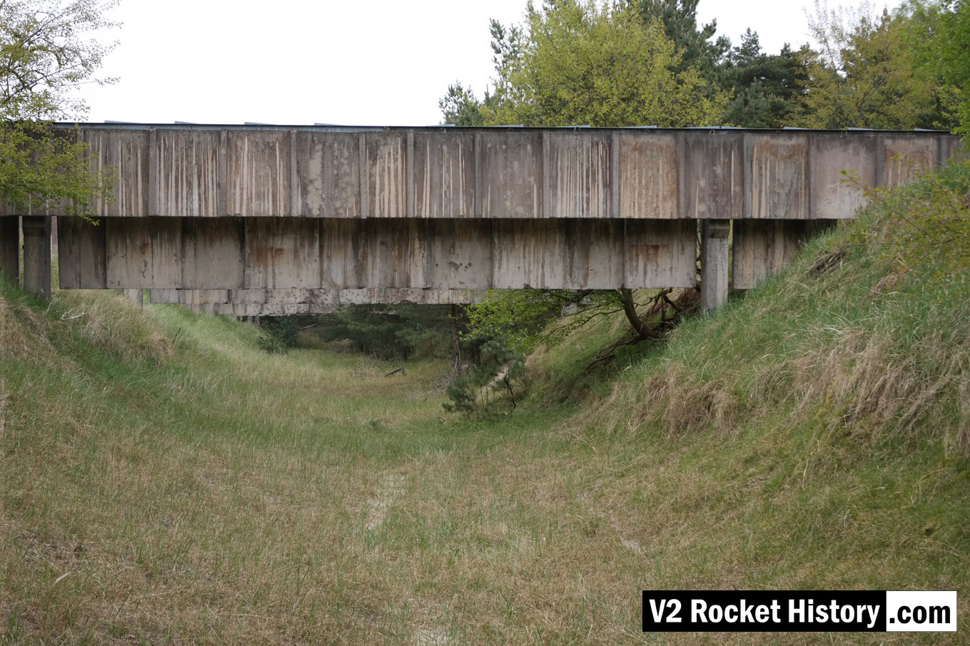
1944 bomb crater near R&MH
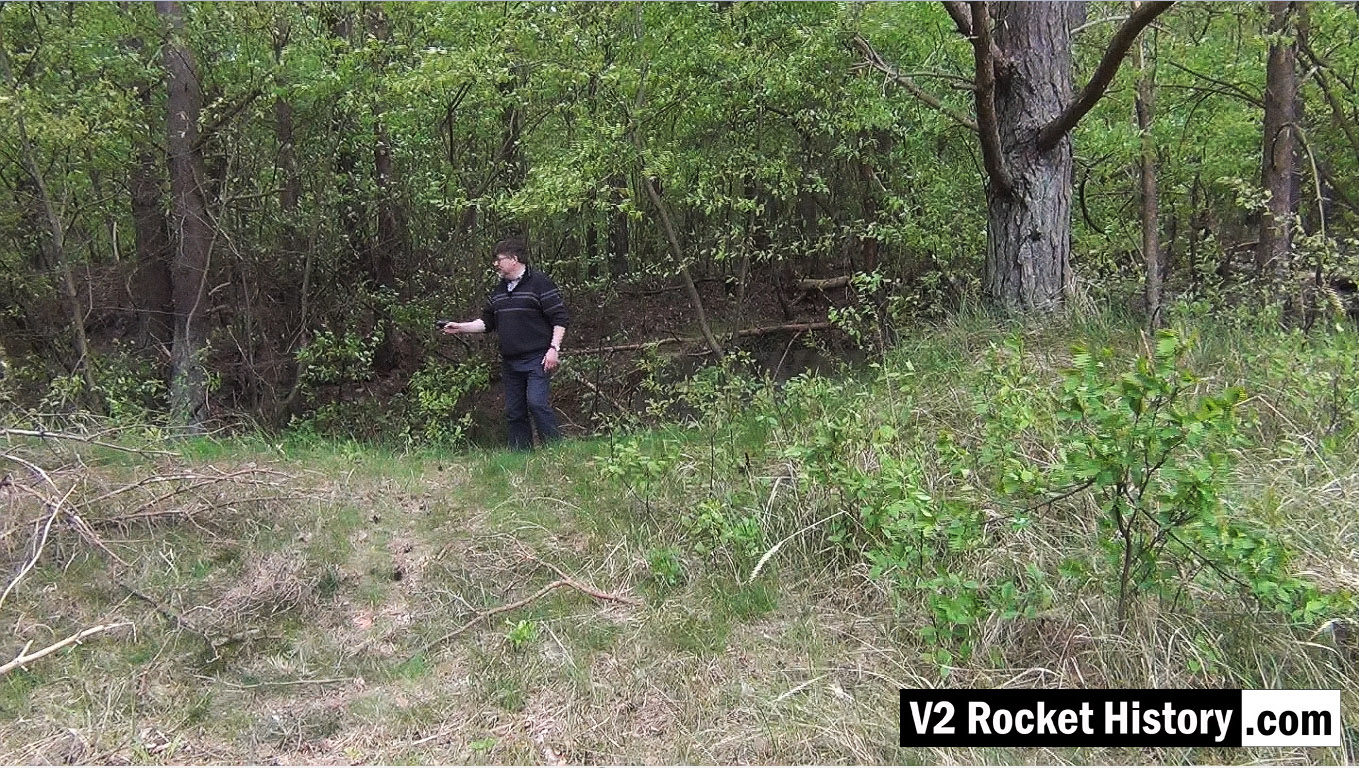
1944 bomb crater near R&MH
This video still shows Robert in front of a bomb crater on the West or opposite side of the rail lines and road that pass the Repair & Maintenance Hall (R&MH). The crater like so many others, created in a fraction of a second, in August 1944 during a US air raid, has developed in to a thriving eco-system that now teems with all kinds of life. After the passage of more than 70 years the crater is still deep and well defined. There are hundreds of craters like this in the area.
1944 bomb near R&MH – 2nd view
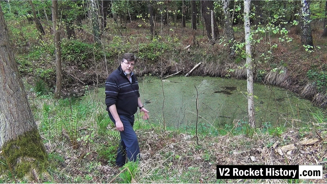
1944 bomb near R&MH – 2nd view
This video still shows the same bomb crater from a slightly different angle. The crater like so many others, created in a fraction of a second in August 1944 during a US air raid, has developed in to a thriving eco-system that now teems with all kinds of life. After the passage of more than 70 years the crater is still deep and well defined. There are hundreds of craters like this in the area.
Ruins of materials storage station No 9 next to F1
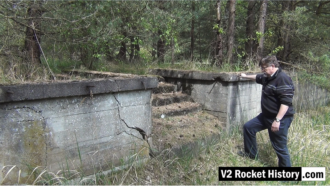
Ruins of materials storage station No 9 next to F1
This video screen grab shows Robert about to climb the steps up onto the rail and road loading station 9 (also called Die Verladerampen or in English, The loading ramps). This storage and loading facility was never finished during the war and was intended to be a more elaborate with large storage buildings – but the pressure of war and constant use of the area prevented further development. The area is still surprisingly intact today with a strong correspondence between modern ground detail and historical reconnaissance photography.
V2 missile relics in F1 factory prisoner ‘free movement’ area
V2 missile relics in F1 factory prisoner ‘free movement’ area
V2 missile parts in F1 prisoner turn-out or ‘free movement’ area. The location referred to is a large triangular shaped area situated on the South-East side of the pre-propuction hall Fertigungshalle Eins (F1). The area was fenced off with a high barbed wire fence (a portion of which was electrified) with guard towers every 60 metres.
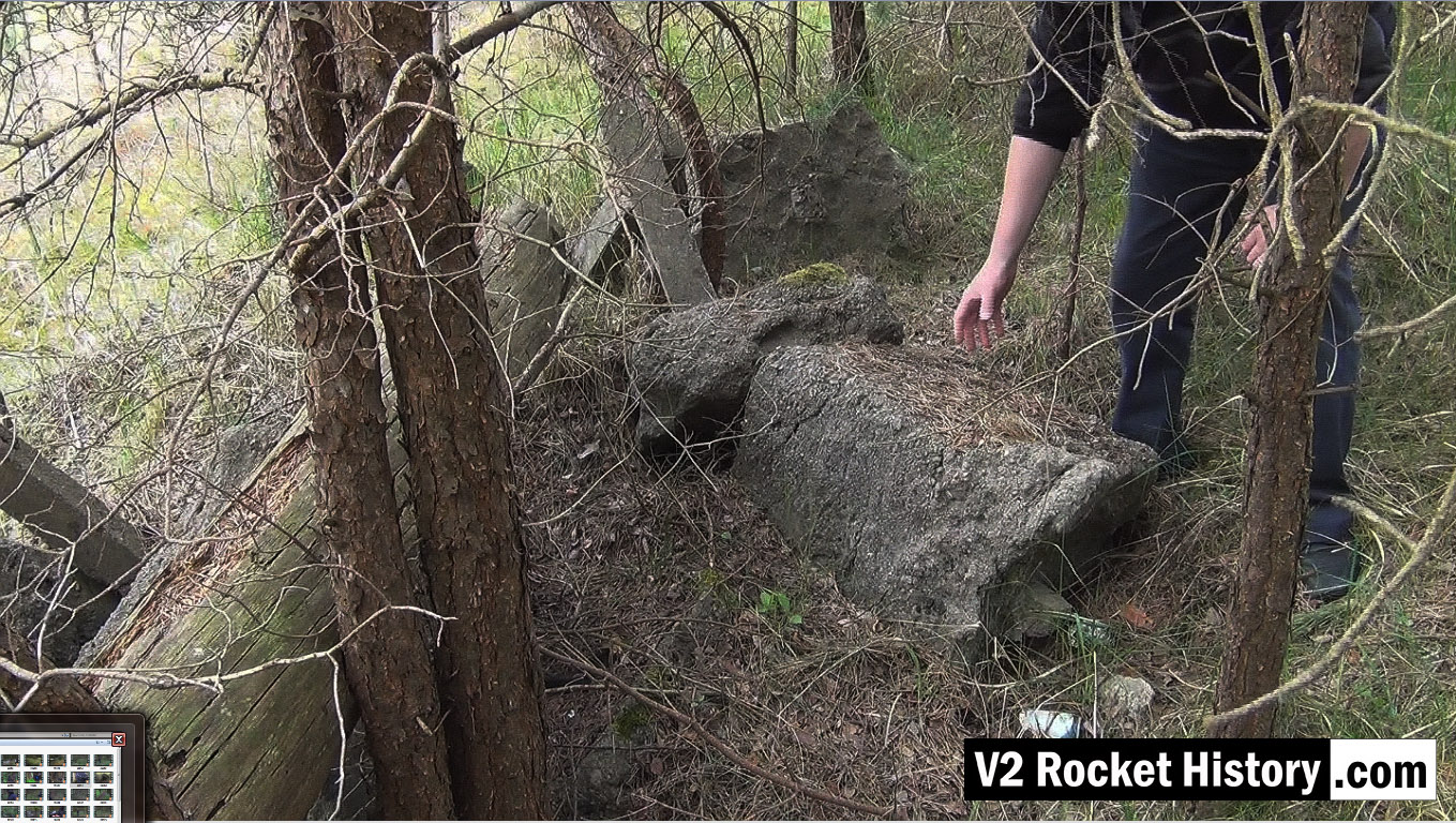
Still frame from F1 video
Still frame from F1 video
This image shows part of a pile of concrete castings that form the below ground foundations for part of the electrified fence that was built around F1 in the summer of 1943. The fence was built on the instructions of Arthur Rudolf, who was responsible for F1, by the first 200 forced labourers to arrive at the F1 labour camp in June 1943. These crude castings are the result of digging a narrow hole in the ground for the concrete fence post and filling the area around the post with the concrete mix. The sizable variation in the depths of the concrete castings, and the fact that in a number of casting blocks the post has plunged through the concrete mix and penetrated from 100 to 300mm into the ground below, strongly suggests this work was carried in hast and/or by men inexperienced in the normal procedures of this type of basic ground-work.
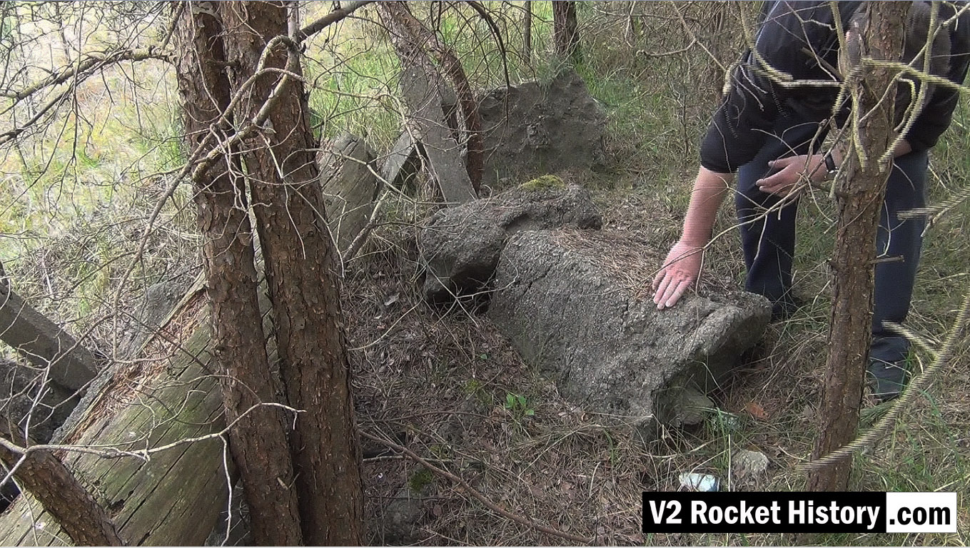
Another screen grab from F1 video
Another screen grab from F1 video
This image shows part of a pile of concrete castings that form the below ground foundations for part of the electrified fence that was built around F1 (see previous photo for details). You can see the area that these posts once secured in the second black and white recce image in this gallery. The fenced off area is the large triangular shape you can see joining the North-East South-East corners of F1 (ie the long wall of F1 facing the shore). Quite why and exactly when someone mustered men or machines to pluck these lumps of concrete out of the ground and move them 100 to 200m is beyond me – why not just bulldoze them under like everything else on this site?
East German army shooting range near F1 and admin area
East German army shooting range near F1 and admin area
Photo shows the remains of a shooting range built by the East German Army. In 1944 the area about 200m in front of the camera and to the left of this picture is the emergency rail-loading area used after US air raids in August damaged rail lines and other regular freight loading infrastructure. Today, it is a peaceful thoroughfare used mostly by deer and rabbits.
Oil storage shed – cut down vertical girder with door hanger
Oil storage shed – cut down vertical girder with door hanger
Photo shows the cut stump of an heavy upright support girder. The ragged profile of the cut shows that it has been cut down with an oxygen and gas torch or possibly a larger fuel and oxygen device like a thermal lance. The steel support still has the bottom support pin for a large door. Note that although the girders have been gas-cut there is a great deal of mechanical damage to the steel work that was not caused by the cutting work. Considerable force would be required to bend the middle girder in the way shown, even if it was much longer at the time the bend was created. The upper superstructure of the storage shed may have been part demolished using a bulldozer. Or perhaps the East German Army may have used the site for explosives training – signs of demolition explosive use are in evidence nearby. The map under the album presentation of this picture shows the exact location of the girders.
Bomb damaged F1 factory 1945
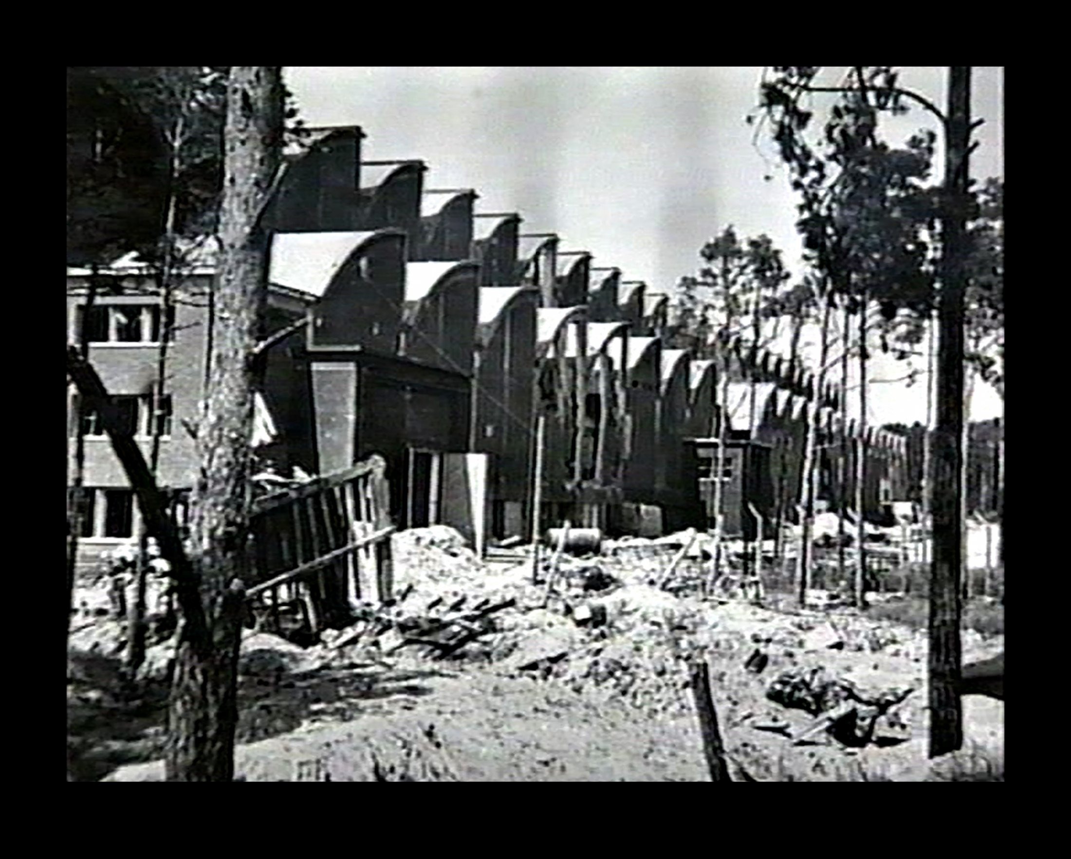
Bomb damaged F1 factory 1945
Bomb damaged F1 factory 1945. The huge V2 rocket factory shown badly damaged by air attack at the end of the war in May 1945
Peenemünde: Werk Sud attacked by US bombers August 1944
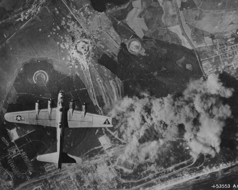
Peenemünde: Werk Sud attacked by US bombers August 1944
Peenemünde: Werk Sud attacked by US bombers August 1944 in a daring daylight raid. The two large halls F1 and IW in the lower middle of the photo are under direct attack and smoke can be seen originating from both buildings. Although the August 1944 raids did little to interrupt the volume manufacture of the V2, as virtually all manufacturing and assembly of the missile had moved to central Germany, the raids did bring to an almost complete halt the last small amount of manufacturing work still competed in the giant halls of Werk Sud.
Equipment bays
Askania rudder servo ‘Rudermaschine LRM 3’
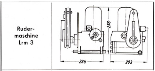
Askania rudder servo ‘Rudermaschine LRM 3’
A schematic drawing of the Askania rudder servo ‘Rudermaschine LRM 3’showing the critical compact dimentions of the device making it ideal for retro fit projects for smaller aircraft.
A4-V2 thrust ring with control servos (Abtriebsring) ©THBC
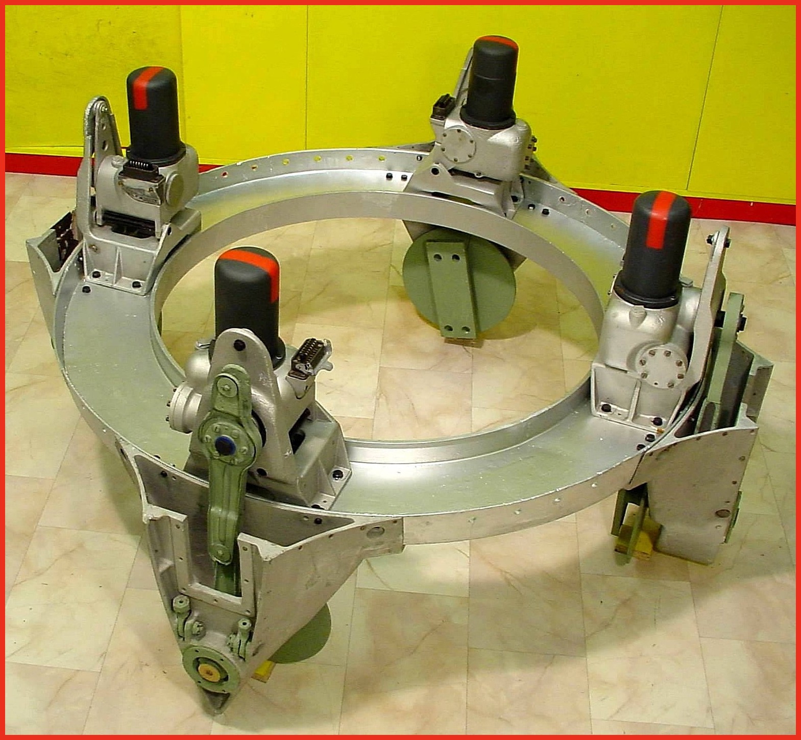
A4-V2 thrust ring with control servos (Abtriebsring) ©THBC
Photo shows cast aluminium thrust ring with electro-hydraulic servos in position. Note different crank lever shapes (pale green arm on servo) for fins 1/3 and 2/4 This excellent restoration is the work of Horst Beck. Photo copyright: The Horst Beck Collection
A4-V2 control surface servo and trim motors. ©THBC
A4-V2 control surface servo and trim motors. ©THBC
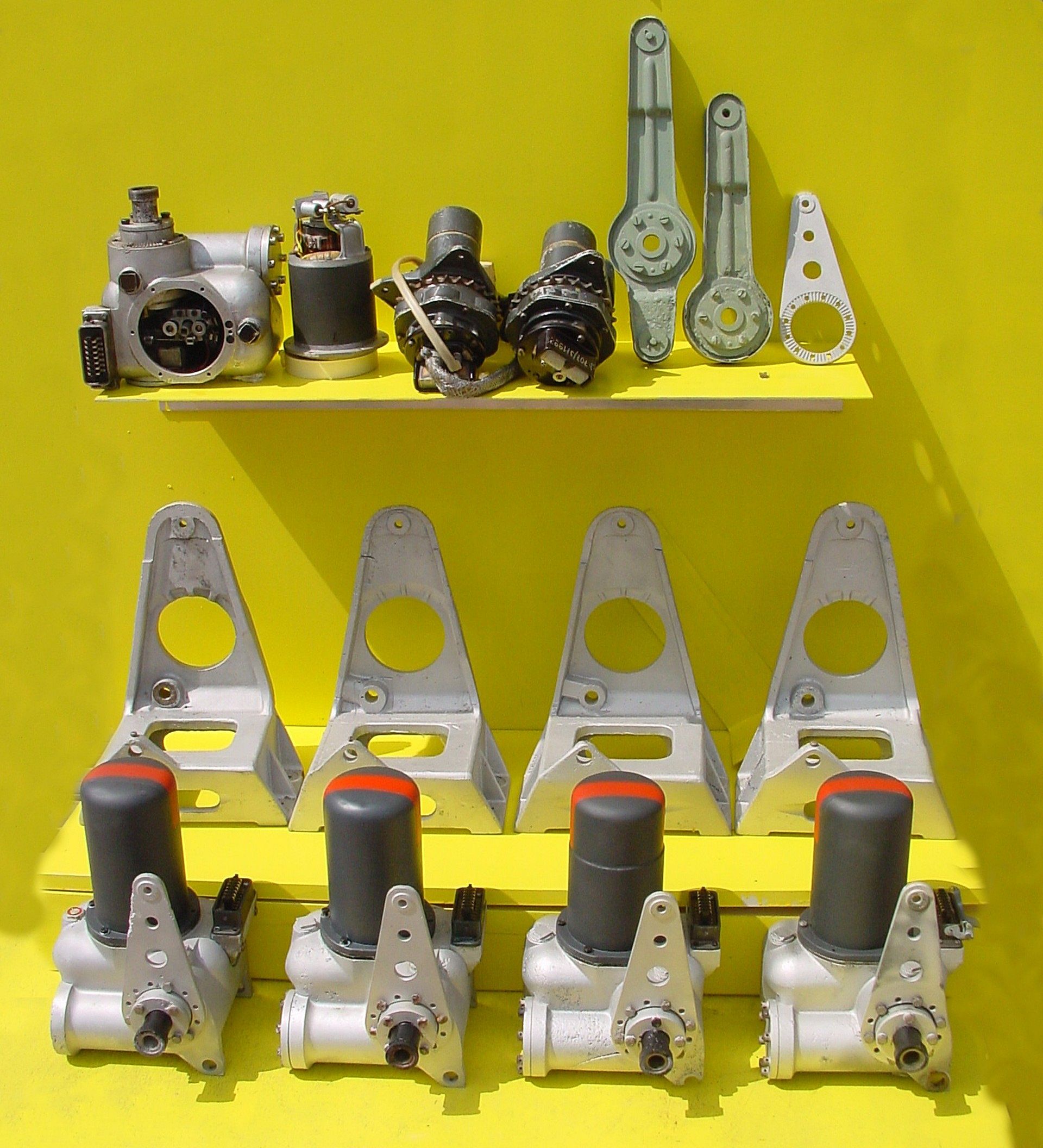
Photo shows a unique display at the Horst Beck Collection (HBC). Over many years Mr Horst Beck has painstakingly acquired and restored many A4-V2 missile parts – and in some cases, reassembled them into complete sub-assemblies. Shown here is part of the collection’s hydraulic servos and trim motor parts display. In the foreground we see four hydraulic servos, and behind them their A frame mounting ‘chairs’. The top shelf, from left to right, shows a servo with motor removed (and placed on its right). In the middle, two trim motors and chain sprocket gear-boxes for the aerodynamic trim surfaces on the trailing edge tips of fins 2 and 4. Next the pale green crank levers, the first longer one is for the hydraulic servo that controls the jet vanes and trimmers on fins 1 and 3. The shorter version minus the top horn, is used on the servos for fins 2 and 4. The last, silver coloured item,os a servo stabiliser (all the servos shown have one already fitted). Photo copyright: The Horst Beck Collection

Impact wreckage of electro-hydraulic jet vane servo
Impact wreckage of electro-hydraulic jet vane servo
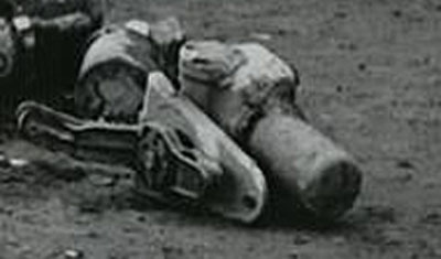
Wreckage of hydraulic servo from fin 2 or 4 of V2 missile that fell on a farm in Essex in March 1945. The motor has been removed and we can see details of the oil gear pump and valve control gear. The 3 position electromagnetic relay switch is visible at the 7 to 8 o’clock position within the open aperture. The push rod that connects the relay to the gear pump valves is also visible as a short brown coloured rod with a fine wire connector at each end, running in towards the gear-valves from the 9 o’clock position. The point that provides electrical current for the motor (which runs all the time and in one direction only) can be seen at the three o’clock position. The black housing has two sets of brass tongues that receive the matching brass spades mounted on the base of the motor for power input. The motor drive shaft has a female square socket coupling to connect the motor to the middle drive gear of the gear pump. A small portion of the square drive shaft of the central gear can just be seen in the photo – in the centre of the valve control block.
Hydraulic servo impact debris
Hydraulic servo impact debris
Hydraulic servo from fin 1 or 3 of the V2 missile, collected with other debris following a combat impact.
Hydraulic servo relics from Nordhausen
Hydraulic servo relics from Nordhausen
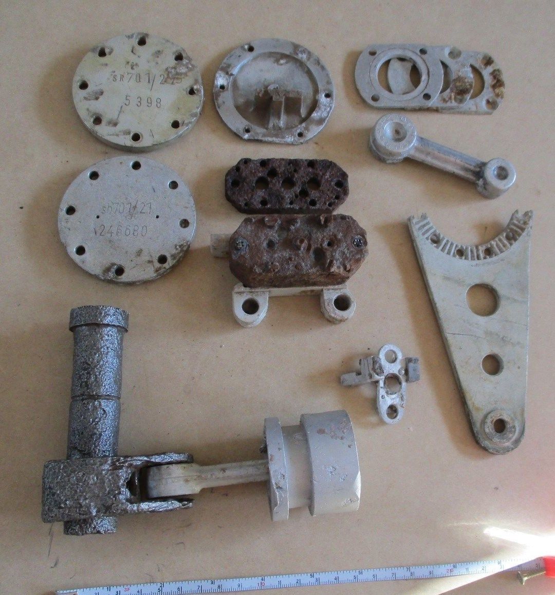
This collection of parts were all found in vicinity of the Nordhausen manufacturing facility. parts include servo crankcase caps -top left, electro-magnetic switch installation plate – middle top, crank bearing covers – top right, gear pump blocks with base – centre, and crank-shaft, piston rod, and hydraulic piston – btm left. The deep recess on the piston circumference is for a rubber seal and is an interesting variation in ring seal design (at least 4 variations of piston design were employed, with three designs flown on combat missiles). A valve tilt seat is visible a little to the right of the piston. A broken servo mount stabiliser is shown – middle right. The cast piston rod, top right, has not been drilled and milled – the part is ‘raw’ as supplied by the manufacturer before machining has been completed. Normally the manufacturer’s details are machined off the metalwork – but not in this rare case. The three letter code gfa is clearly visible on the part and stands for the firm of Otto Fuchs Metallwerke.
Fin and jet vane servo: Hydraulic gear pumps
Fin and jet vane servo: Hydraulic gear pumps
Two Askania (designed) hydraulic gear pumps – the examples shown here have two ceramic insulators with with Nichrome wire type heating elements. The heaters are located at each end of the pump on the long axis. The pump on the right still has its power supply wires attached and was easily repaired and restored to full function in our workshop.This type of pump (with heaters) seem to be rare among the debris of European combat impact sites but fairly common in debris collections emanating from research flights in Peenemünde and parts of Poland. An explanation maybe that the oil could be warmed up sufficiently simply by starting all four hydraulic gear pumps sooner in the pre-launch sequence. The only downside being that the already noisey missile would be making yet more noise in the risky period leading up to launch.
Hydraulic gear pump detail
Hydraulic gear pump detail
Close-up of Askania gear pump relic with oil heaters. This picture shows an unusual feature on the otherwise normal cast aluminium base of this gear pump. The knurled knob positioned between the oil flow balance adjusters has a purpose that is unknown to us. The two oil-flow balance adjuster valves visible in the picture have slot head adjuster screws and you can also see the knurled circumference on each screw. This parallel knurling is engaged by a crease formed in the facing surface of the copper spring strips. The function of these strips is to create tactile feedback that the technician making the adjustment can feel in the handle of the screwdriver. This was done because the gear pump needed to be adjusted in a dark and narrowly confined space.
Gear pump showing flow adjusters and ceramic heater elements
Gear pump showing flow adjusters and ceramic heater elements
Gear pump showing flow adjusters (two slot head screws nearest bottom of picture) and ceramic heater elements situated at each end of the block. The square drive shaft coupler (corroded but still identifiable) has been highlighted in red paint. The open holes either side are the main control valve guides. The copper spring strips visible on each oil flow adjuster provide locking and tactile feed-back for the adjusting process. This relic was recovered from Usedom island.
Gear pump detail showing ceramic insulator with nichrome element
Gear pump detail showing ceramic insulator with nichrome element
Hydraulic gear pump with close up detail showing ceramic heater element insulators with flat, possibly nichome, metal strip element threaded through them. This oil heating system was designed to maintain a specific viscosity of the oil regardless of environmental temperature, to better maintain oil flow rates and thus pump efficiency. The heating system is found only rarely on surviving relics.
A4-V2 graphite jet vane
A4-V2 graphite jet vane
Photo shows a flown graphite jet vane complete with mounting plate and fasteners as well as pre-flight centre index tip. V2 relic from the Horst Beck Collection (HBC). Photo copyright: The Horst Beck Collection
Graphite jet vane replica
Graphite jet vane replica
V2 missile graphite jet vane defector replica made for V2 Rocket History.
Graphite vane rocket jet deflector replica
Graphite vane rocket jet deflector replica
V2 missile graphite jet vane defector replica made for V2 Rocket History. This accurate replica shows the distinctive pantograph mill tool ‘witness’ marks well.

Restored graphite vane thrust ring support housings. ©THBC
Restored graphite vane thrust ring support housings. ©THBC
Photo shows four restored graphite jet vane support blocks and bearing housings. The round plates we can see here act as heat sinks and allow heat to radiate away from the support block and bearing to help prevent expansion due to relatively rapid and uneven temperature distribution accumulation. The graphite vanes were quite brittle and cracking caused by rapid and uneven expansion could cause the vane to disintegrate. The area around the graphite vanes was exposed to the accumulation of heat not merely as a result of duration of the motor burn time but temperature was also increased at higher rates as the jet plume expanded with the decreasing atmospheric pressure as the missile gained altitude. This excellent restoration is the work of Horst Beck. Photo copyright: The Horst Beck Collection
A4-V2 air rudder detail. ©THBC
A4-V2 air rudder detail. ©THBC
Photo shows restored air-rudder and fin detail. The grey painted barrel-strainers are both adjusted independently to reduce slack in the drive chain and avoid introducing a deflection bias in the air rudder. The 1.9kg counterbalance weight normally located at the top of the trim fin (or air rudder) is missing in this presentation. This excellent restoration is the work of Horst Beck. Photo copyright: The Horst Beck Collection
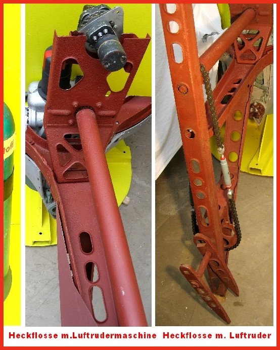
Detail of fin 2 or 4 showing trim motor and drive chain
Detail of fin 2 or 4 showing trim motor and drive chain
Photo shows partially restored air-rudder and fin detail. The image on the left shows the relationship of the trim motor to the air rudder drive shaft on fins 2 and 4. A chain similar in gauge to the type used on a push-bike and yet, at the other end of the shaft, the chain transmitting the torque of the trim motor to the air-rudder drive sprocket has a heavy gauge chain similar to that found on a 1000CC motor-cycle! This excellent restoration is the work of Horst Beck. Photo copyright: The Horst Beck Collection

Ernst Steinhoff
Ernst Steinhoff
Ernst Steinhoff, chief of the BSM workshop (Guidance and Control) in the development works Peenemunde.
Missile guidance equipment
Images of guidance and missile control equiment


Missile guidance equipment
Images of guidance and missile control equiment
LEV-3 Horizont and Vertikant gyroscope system 1940
category:Missile guidence, Sub-assemblies


Description
LEV-3 V2 missile gyroscope system with mounting plate. The third component of this system, the Muller gyroscopic accelerometer, is missing – the 2x mounting points can be seen on the right-hand side of the mounting plate.
Location
