

Archives: Gmedia Albums


The Enigmas

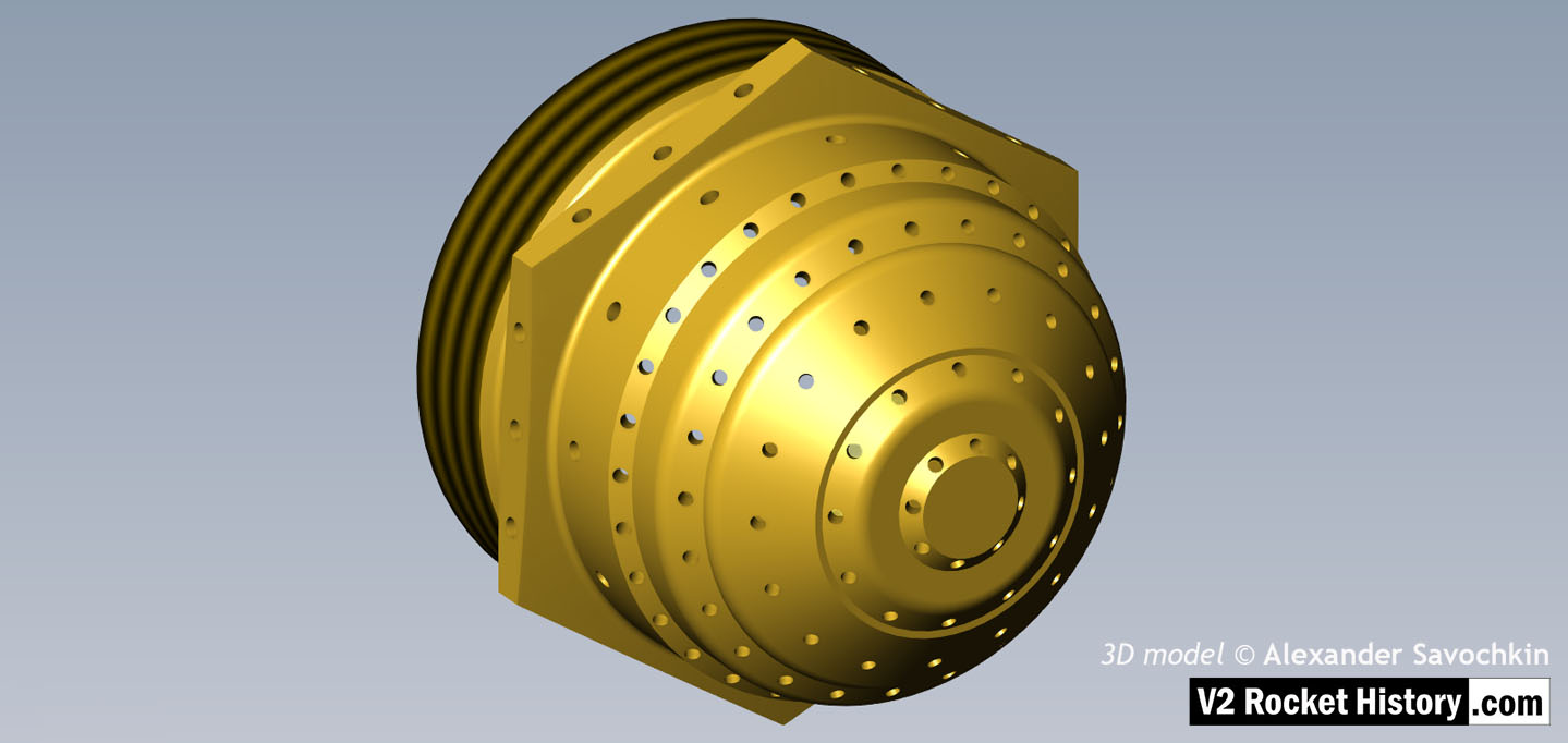
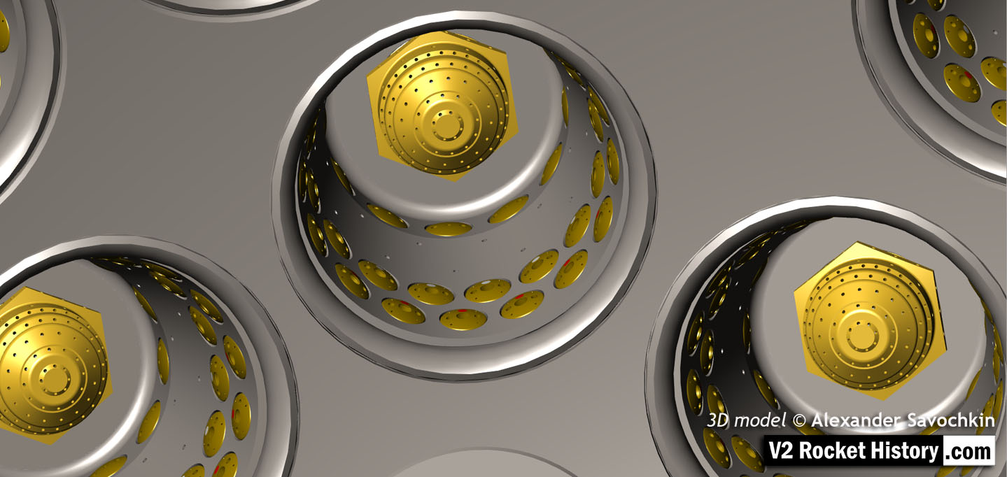
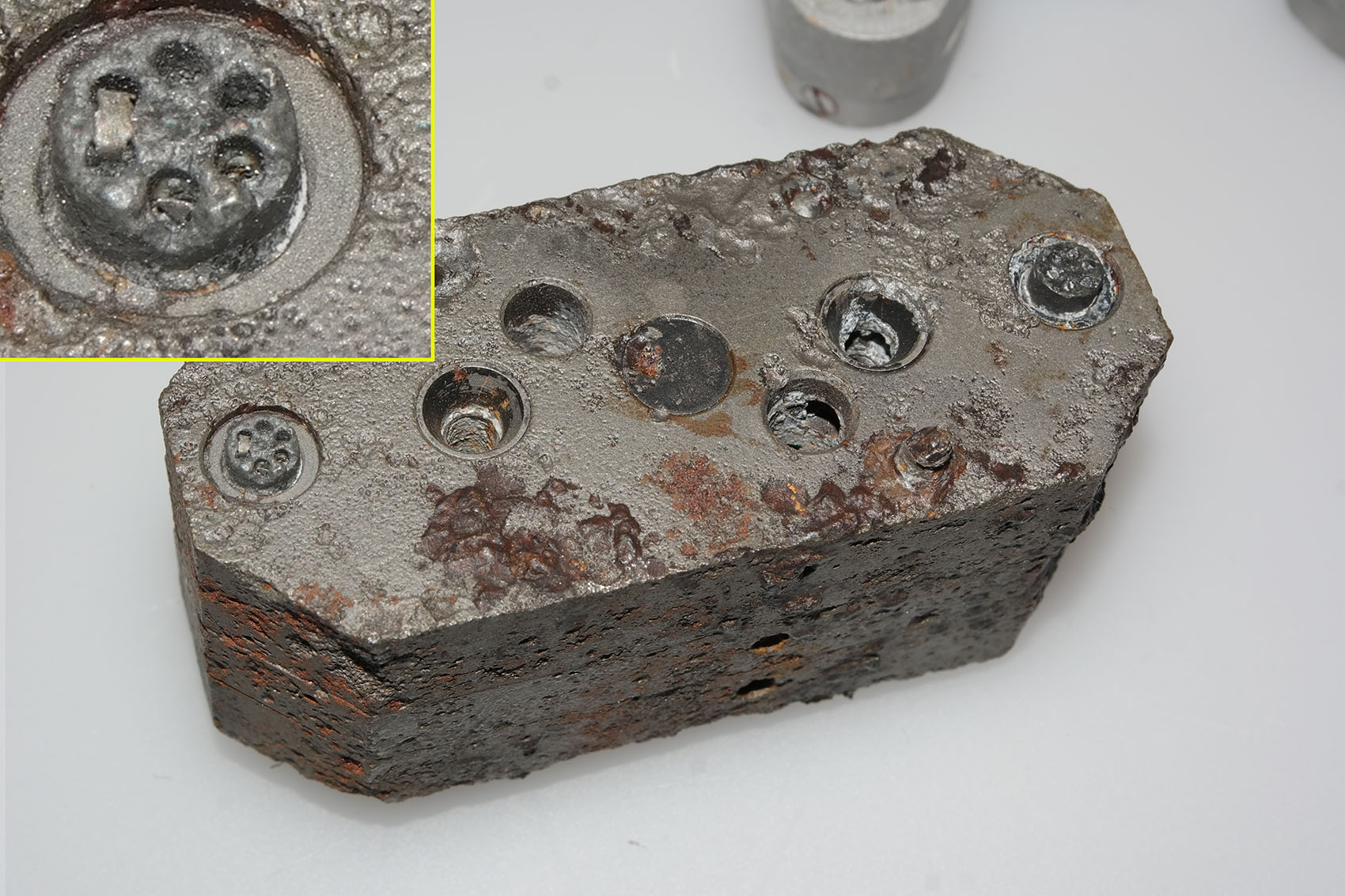
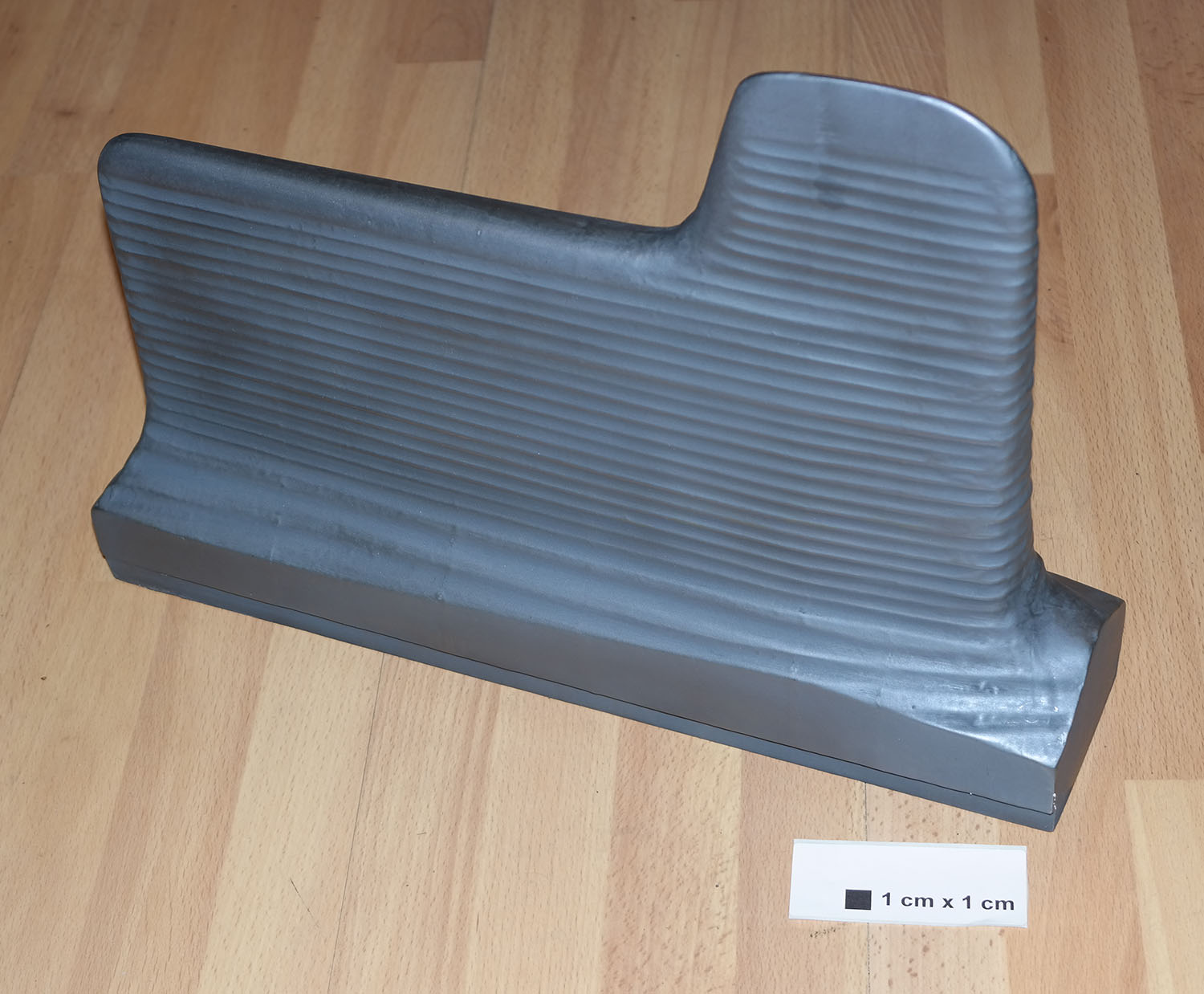
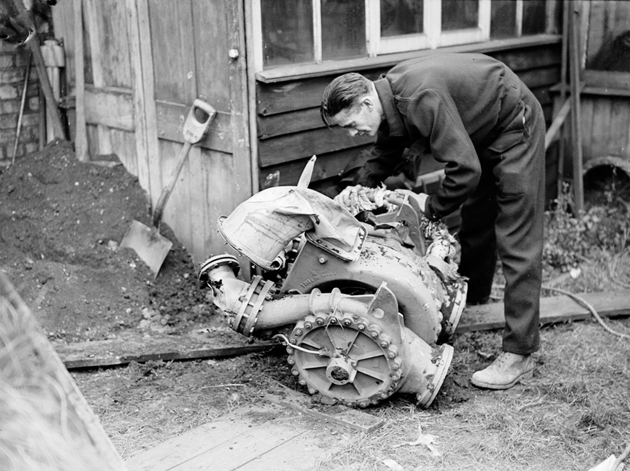
25-Ton aluminium injector pot from 1940/41
25-Ton aluminium injector pot from 1940/41
Relic of prototype A4 25-ton 1940/41 aluminium injector head basket (or pre-chamber) showing 68 copper alloy inserts in 5 rows. The standard configuration would later become 44 inserts in 3 rows 25 2mm diameter drilled holes in two rows situated at row 3 and 4 (counting from nearest the camera). Photo courtesy Host Beck Collection
| Album | V2 rocket fuel injector inserts |
| Categories | Anatomy of the V2, Combustion |
V2 rocket injector head – LOX Spray nozzle 1
V2 rocket injector head – LOX Spray nozzle 1
Brass liquid oxygen (LOX) spray nozzle.Note: the thread is shown in simplified graphic form. 3D model by Alexander Savochkin
V2 rocket injector head – LOX Spray nozzle 2
V2 rocket injector head – LOX Spray nozzle 2
Brass liquid oxygen (LOX) spray nozzle. Note: the thread is shown in simplified form. 3D model by Alexander Savochkin
V2 engine Fuel And LOX Diffuser cup – Internal and external
V2 engine Fuel And LOX Diffuser cup – Internal and external
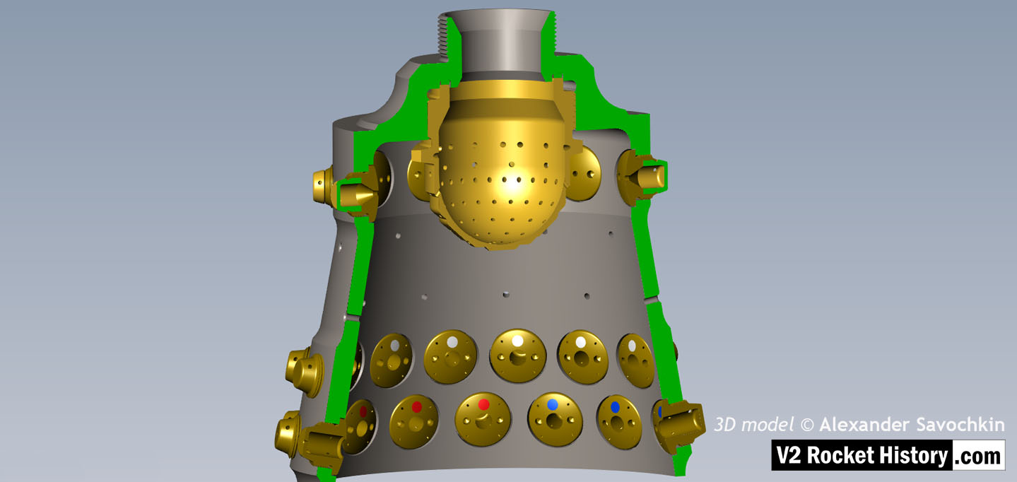
One of the 18 liquid propellant (LOX and fuel) diffuser cups, showing three rows or echelons (A,D,& E) of brass injector inserts as well as two rows of drilled fuel feed holes. The LOX spray head is shown in the centre. 3D model by Alexander Savochkin
Fuel And LOX Diffuser Cup Cutaway 3
Fuel And LOX Diffuser Cup Cutaway 3
Cutaway showing echelon A with 2-part 2131E fuel injector inserts at the top of a propellant diffuser cup. Note the close proximity of the injector inserts to the simple ‘watering can’ type LOX spray head. One row of drilled fuel feed holes can be seen below the inserts. 3D model by Alexander Savochkin
Lower section Fuel And LOX Diffuser Cup Cutaway 2
Lower section Fuel And LOX Diffuser Cup Cutaway 2
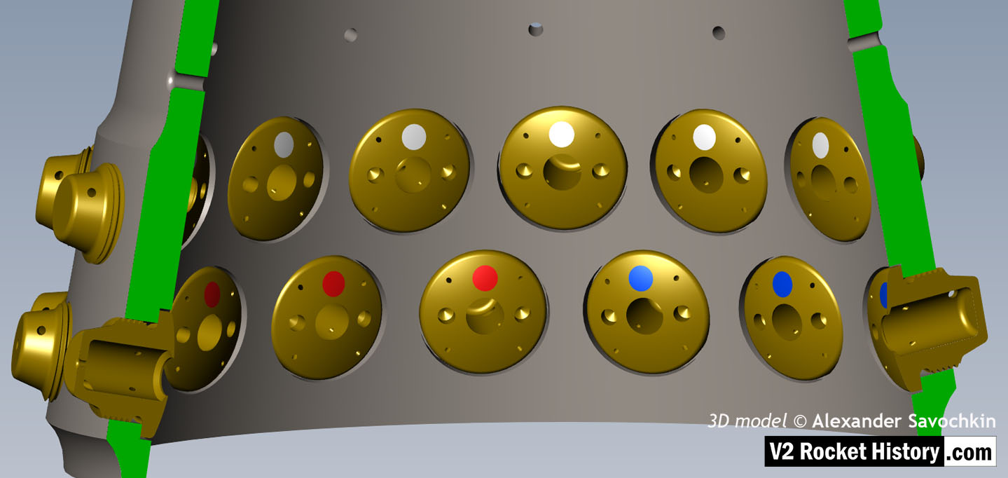
This images shows a cutaway of a burner cup from outer Ring I of the injector head and shows injector insert eschelon D, & E as well as one row of drilled feed holes. Three fuel injector insert types can be seen: Top D, = 3303D (white), lower E, = 3304D (red), and E, = 3305D (blue). 3D model by Alexander Savochkin
Fuel And LOX Diffuser Cup Cutaway 1
Fuel And LOX Diffuser Cup Cutaway 1
This images shows a burner cup from outer Ring I of the injector head and the cutaway shows injector insert eschelon A,D, & E as well as two rows of drilled feed holes. Four fuel injector insert types can be seen: Top, A = 2131E, lower D, = 3303D (white), lowest E, = 3304D (red), and E, = 3305D (blue). 3D model by Alexander Savochkin
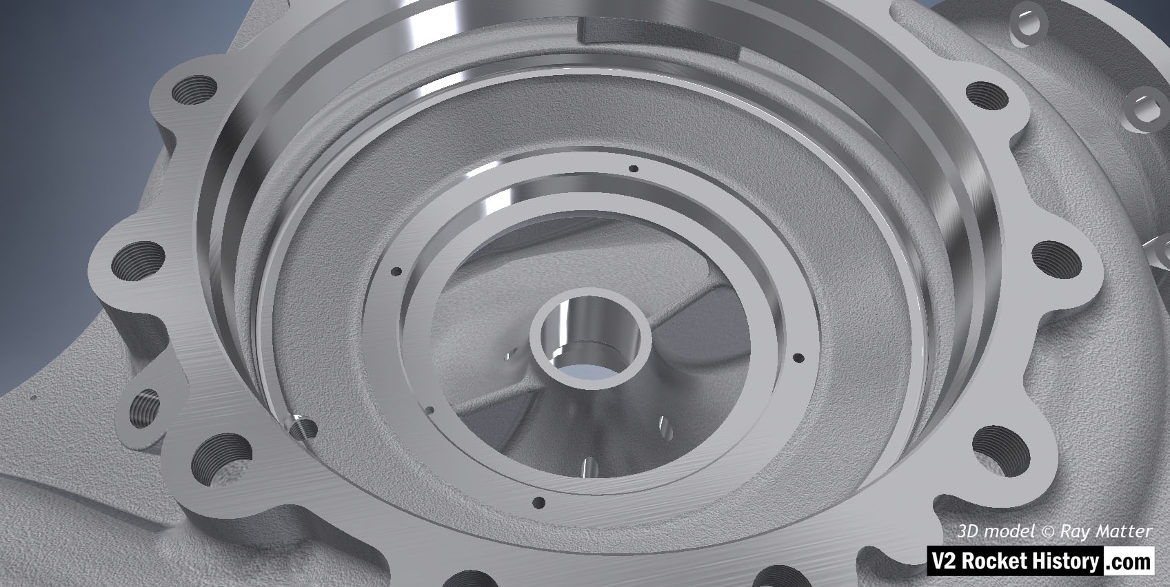
V2 Fuel and LOX Diffuser Cup general view
V2 Fuel and LOX Diffuser Cup general view
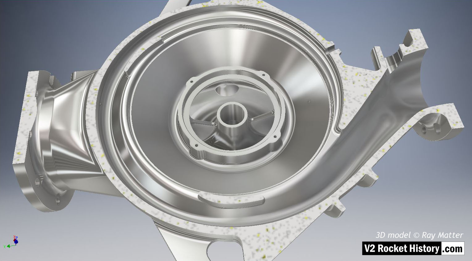
General view of the propellant diffuser cup inner core. The swirl caps of fuel injector inserts in positions A,D,& E can be seen clearly on the outside of the core as well as the central holes in the 3304D (red) inserts.The two rows of drilled fuel feed holes are also well shown. 3D model by Alexander Savochkin
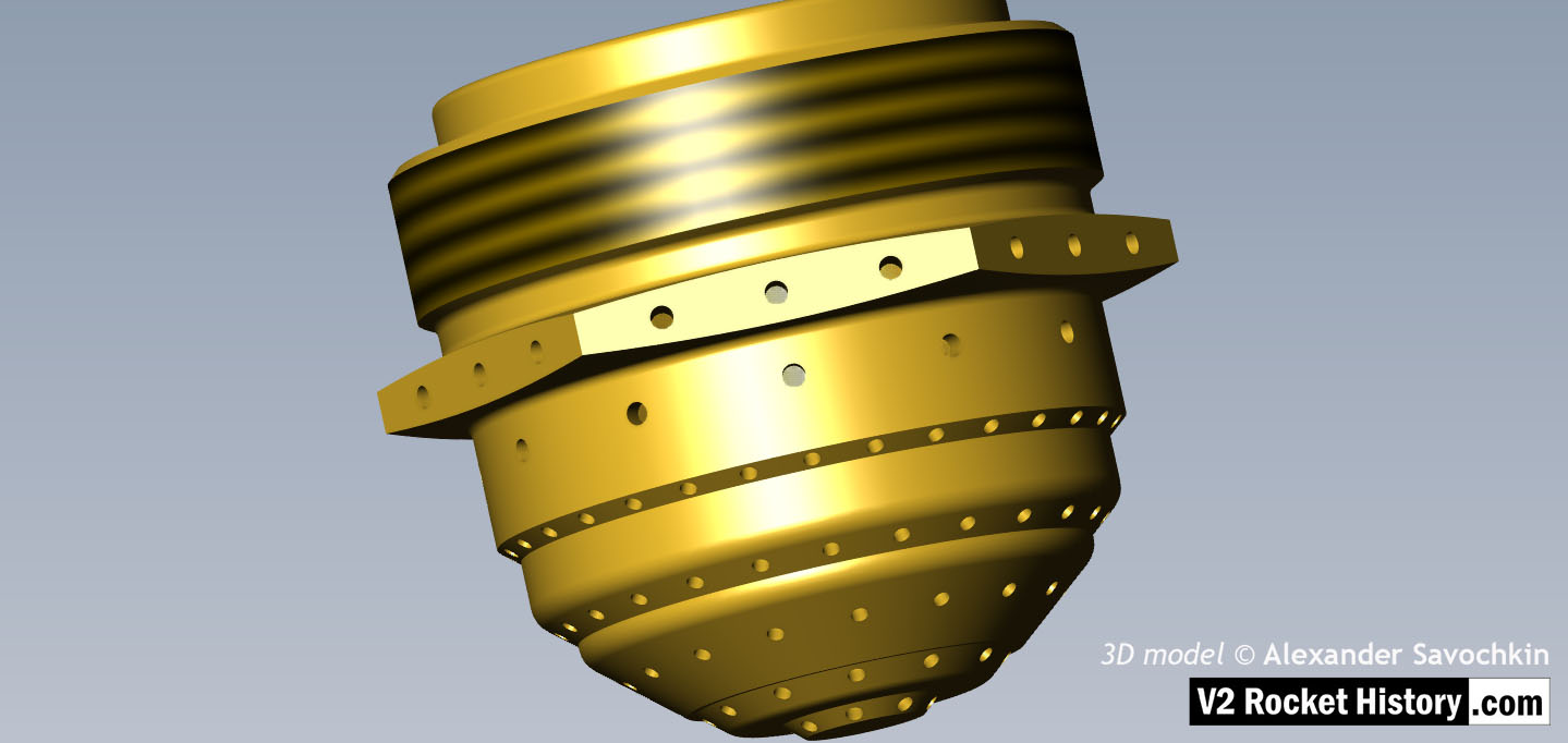
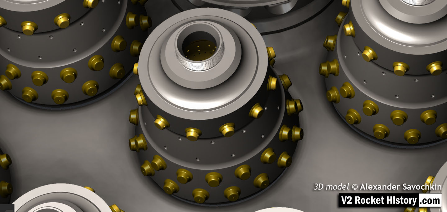
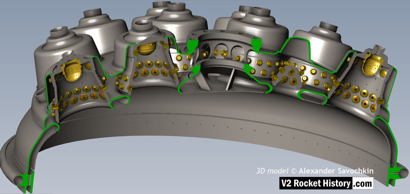
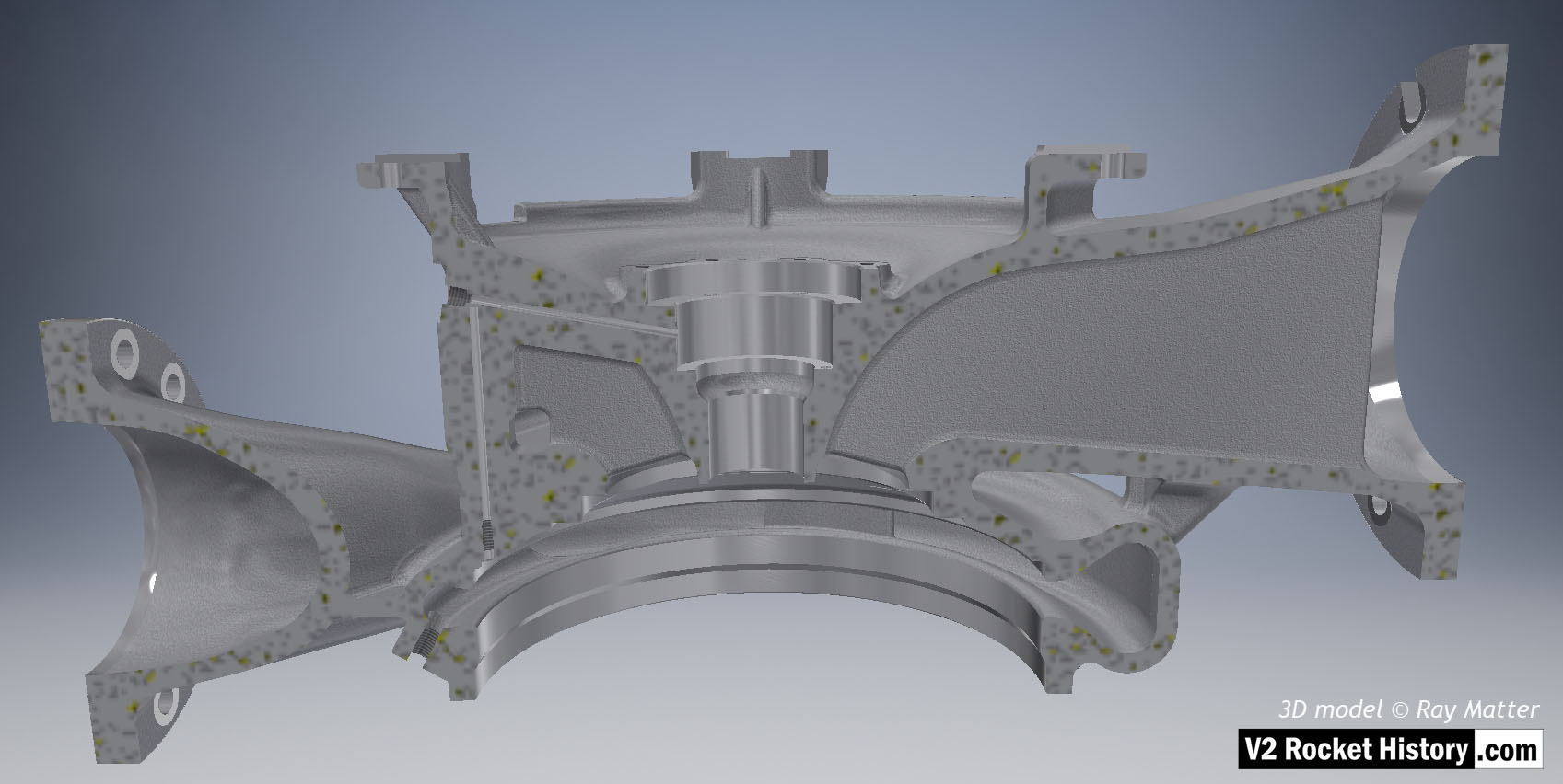
18-pot Upper Veil Manifold detail
18-pot Upper Veil Manifold detail
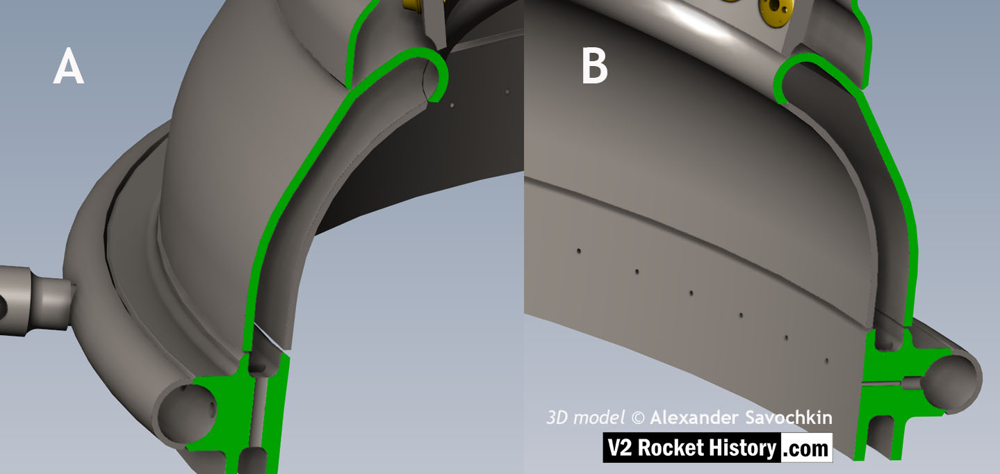
Close-up detail showing independent pathway for fuel passing into injector head and fuel passed down from the head to be used for veil cooling system. Fig. A shows vertical passages for overall fuel feed to the head and Fig.B shows horizontal pathway for veil coolant fed from the head via the veil coolant distributor ring or manifold. 3D model by Alexander Savochkin
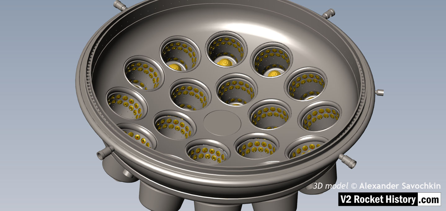
18-pot Head: Underside close-up detail
18-pot Head: Underside close-up detail
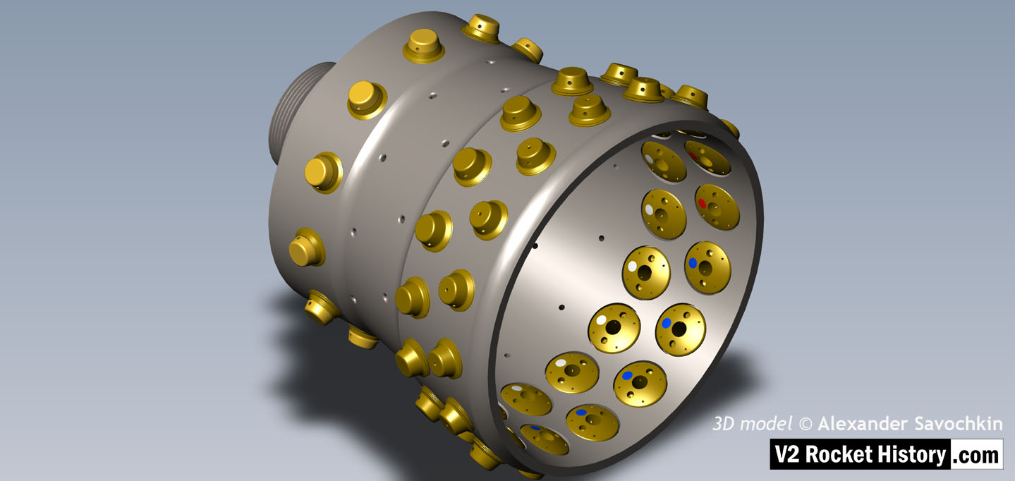
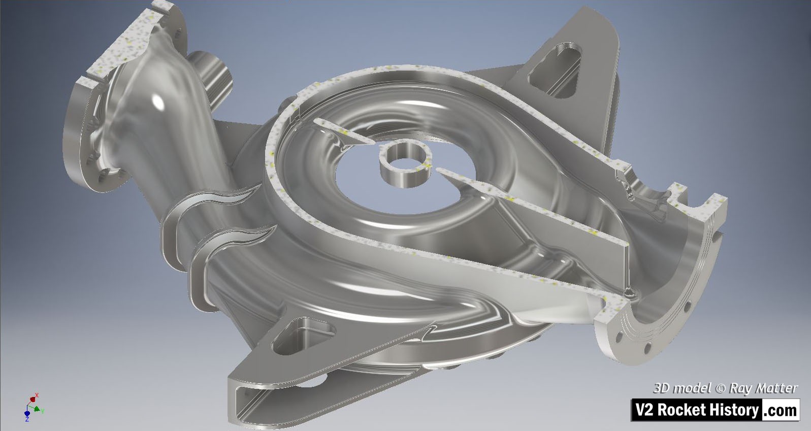
Underside view of injector head showing liquid propellant (LOX and fuel) diffuser cups, (see other images for insert and position nomenclature). Of note in this image are the pointing angles of the cups, positioned on a parabolic section to focus the propellant nebular stream into the central axis of the combustion space. Also of note are the large areas between each cup NOT employed in the injection process – initiating ‘clumpy’ and uneven propellant mixing initially below the injector face but also carried forward into the combustion space. The LOX spray head is shown in the centre of each cup. 3D model by Alexander Savochkin
V2 rocket 18-pot Head Underside
V2 rocket 18-pot Head Underside
Inverted view of injector head showing liquid propellant (LOX and fuel) diffuser cups, (see other images for insert and position nomenclature). Of note in this image are the pointing angles of the cups, positioned on a parabolic section to focus the propellant nebular stream into the central axis of the combustion space. Also of note are the large areas between each cup NOT employed in the injection process leading to structured propellant mixing as opposed to even homogeneous mixing. The four veil cooling inlet connectors are well shown. 3D model by Alexander Savochkin
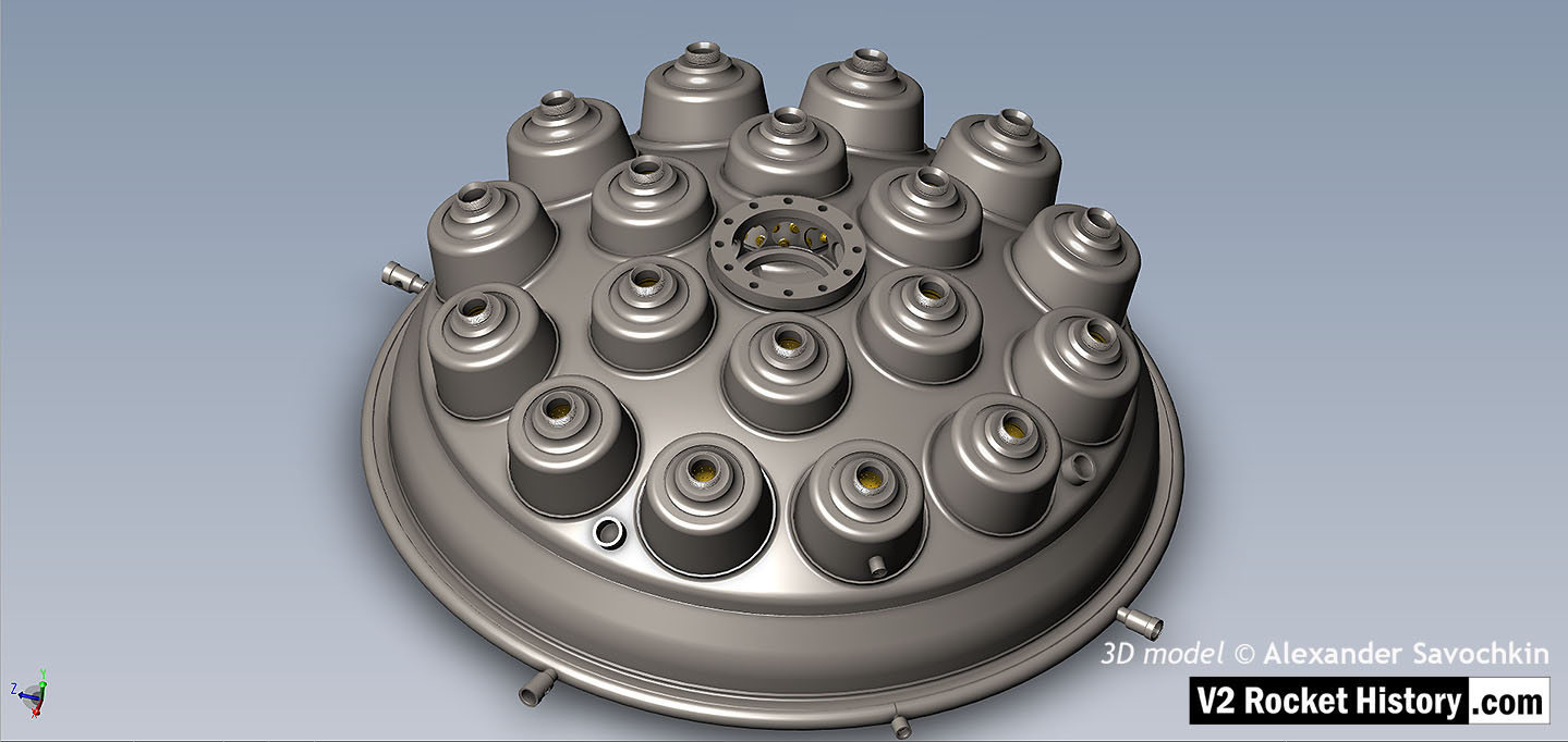
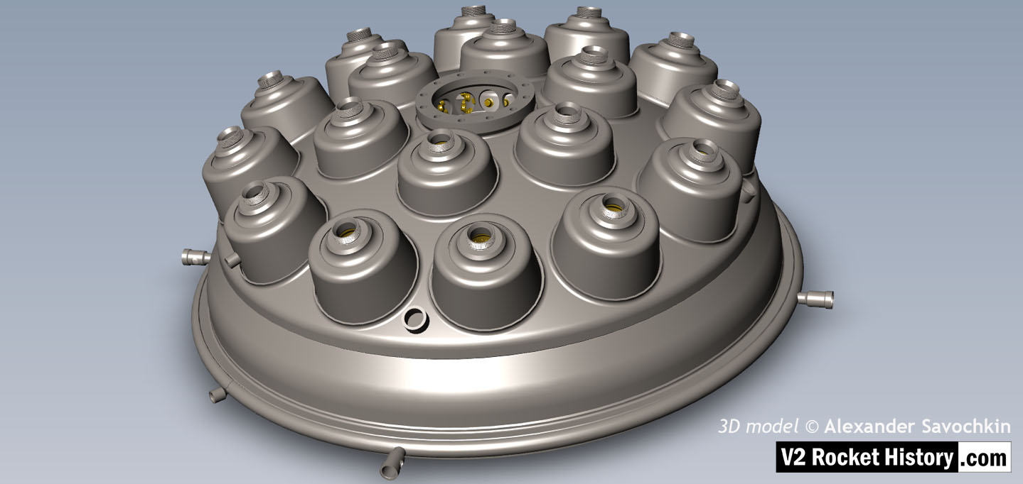
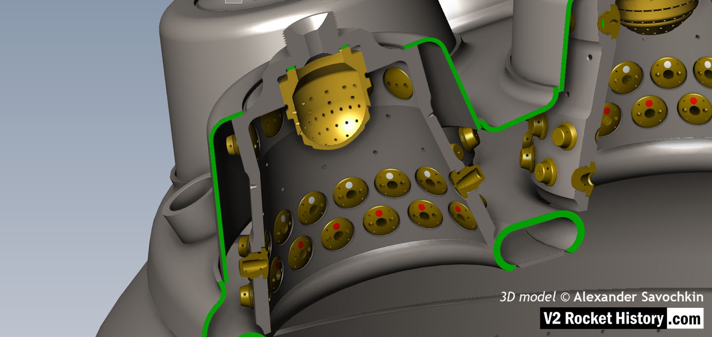
V2 rocket 18-pot Head: Top
V2 rocket 18-pot Head: Top
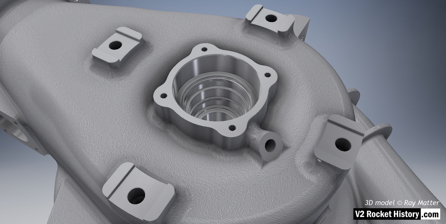
View of injector head showing 18 liquid propellant (LOX and fuel) diffuser cups and head fuel valve seating ring at centre, (see other images for insert and position nomenclature). Visible immediately below the valve seat are the large connecting holes that allow fuel to flow from the inlet manifold and cooling jacket to the injector space (some brass injector inserts can be seen through the holes) after the head fuel valve is released to be opened by the turbo-pump supply pressure. The four veil cooling inlet connectors are well shown as are two of the outlet connection holes immediately above them. 3D model by Alexander Savochkin
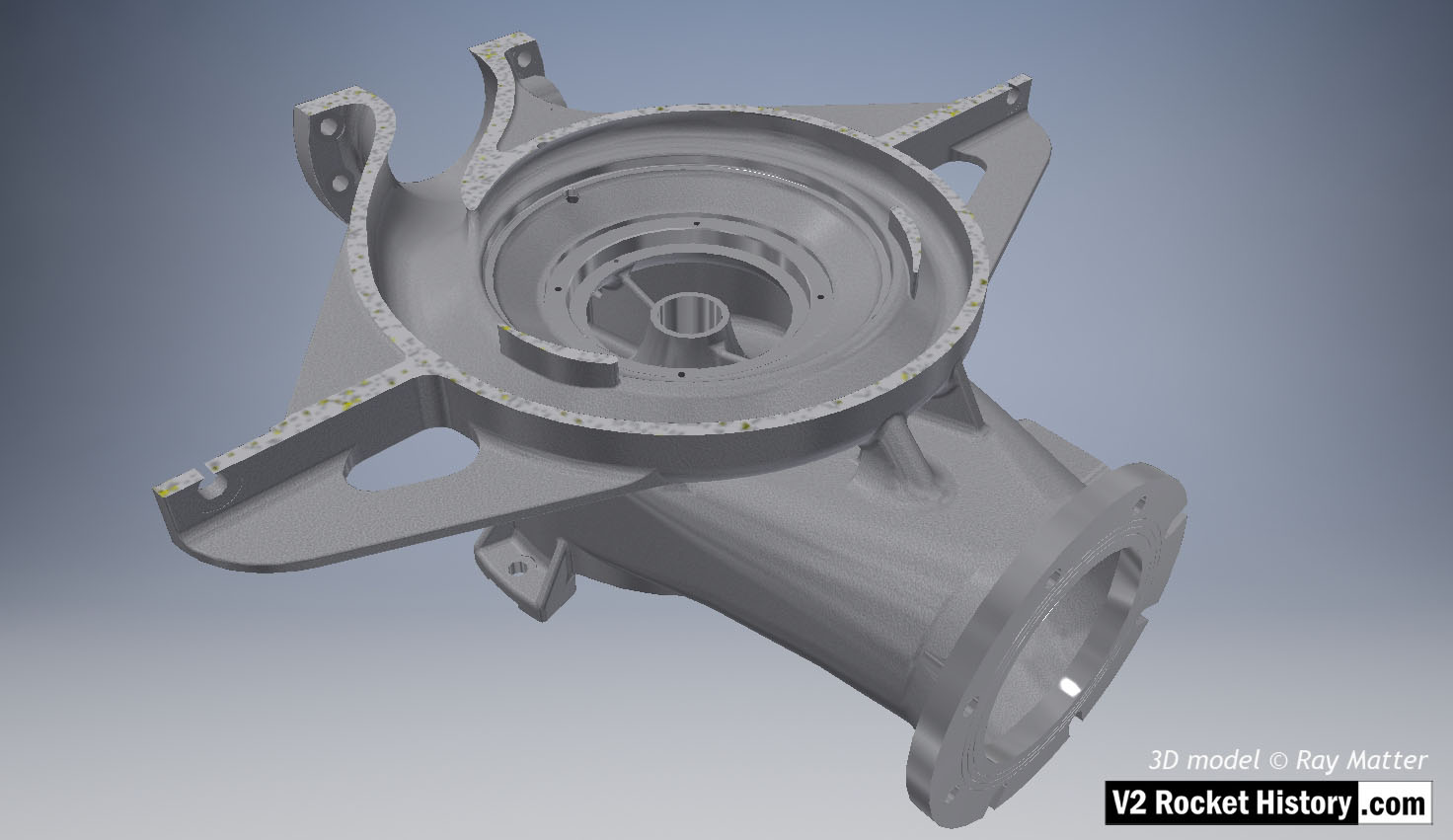
18-pot Head: Top Plate removed to show cores
18-pot Head: Top Plate removed to show cores
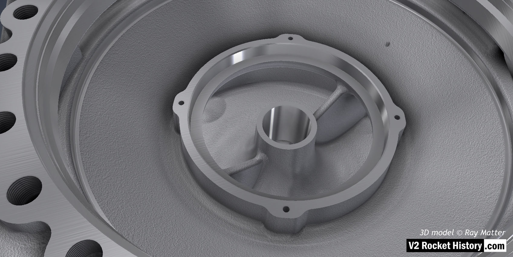
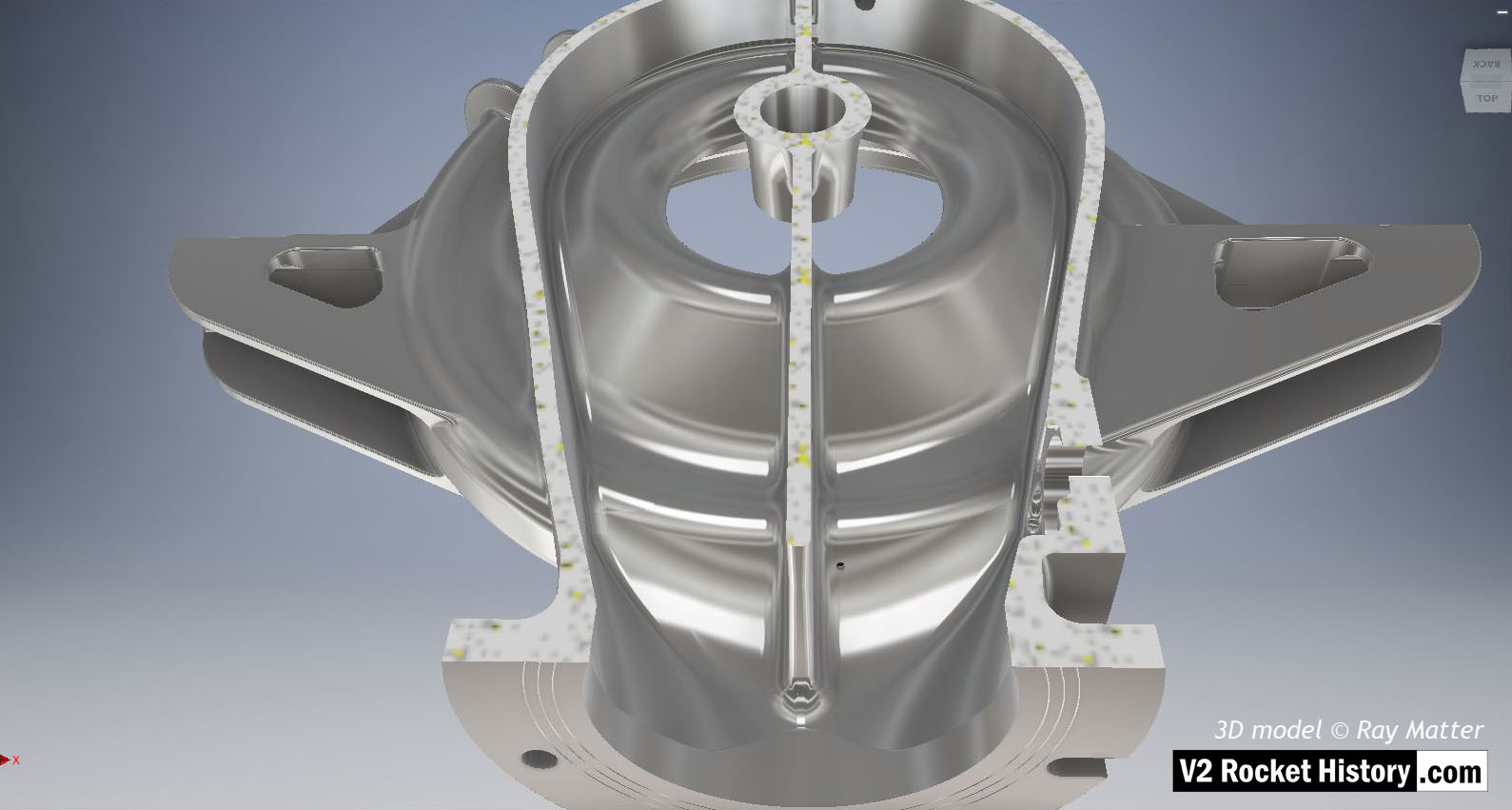
View of the top of the injector head, with outer cups and pressed steel capping piece removed, showing, propellant diffuser inner cores with injector inserts and LOX supply pipe connection thread. The LOX spray head can be seen inside the LOX pipe connector. The swirl caps of fuel injector inserts in positions A,D,& E can be seen clearly on the outside of the cores and the two rows of drilled fuel feed holes are also well shown. 3D model by Alexander Savochkin
25-ton thrust 18-pot injector head: Top 1
25-ton thrust 18-pot injector head: Top 1
Another view of injector head showing liquid propellant (LOX and fuel) diffuser cups and head fuel valve seating ring at centre, (see other images for insert and position nomenclature). Visible immediately below the valve seat are the large connecting holes that allow fuel to flow from the inlet manifold and cooling jacket to the injector space (some brass injector inserts can be seen through the holes) after the head fuel valve is released to be opened by the turbo-pump supply pressure. The four veil cooling inlet connectors are well shown as are two of the outlet connection holes immediately above them. 3D model by Alexander Savochkin
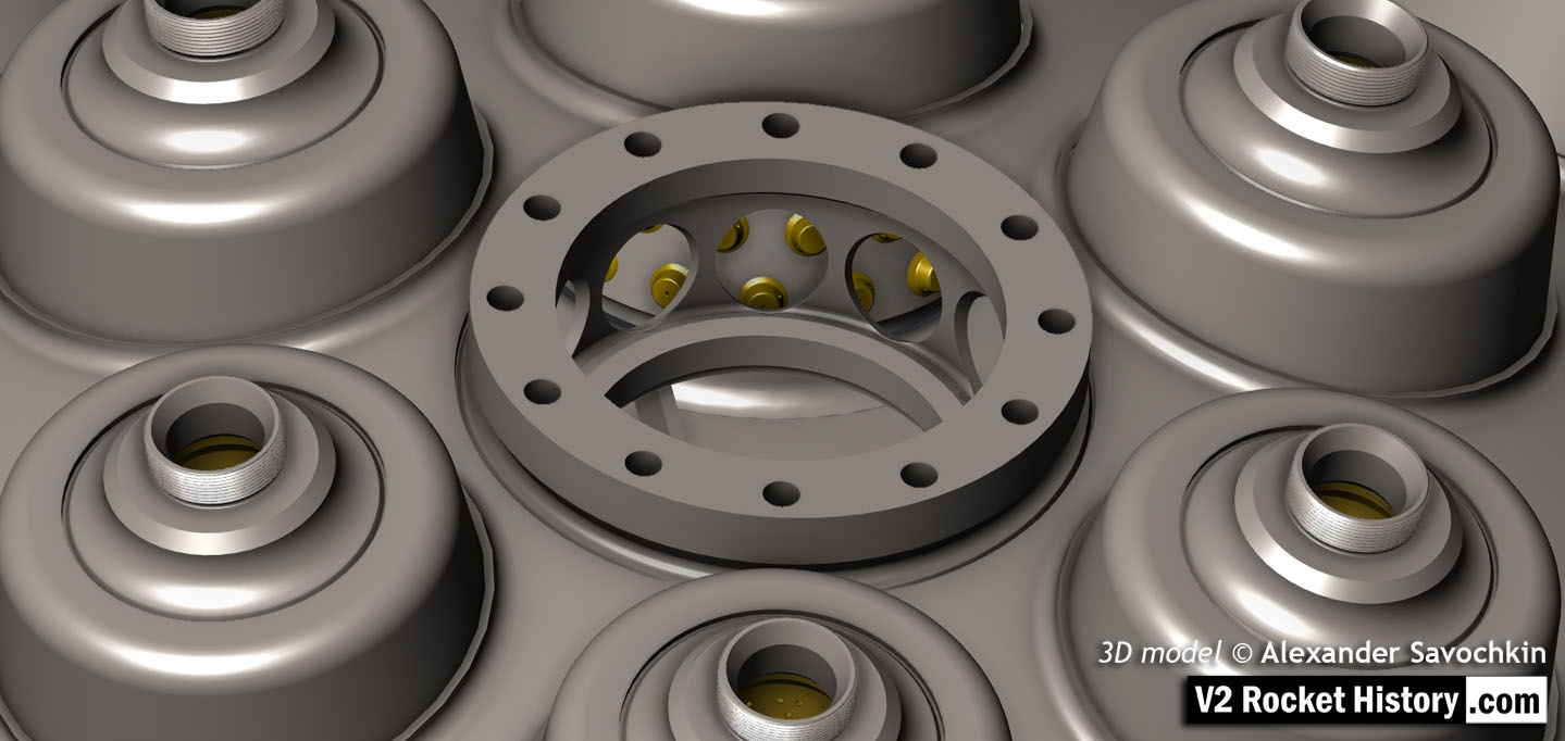
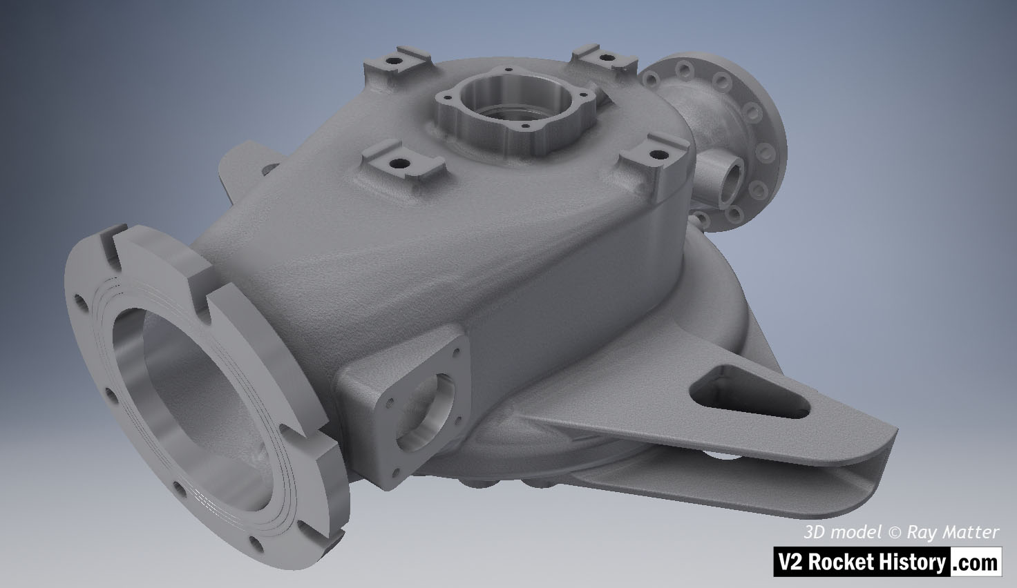
18-pot Head Fuel Valve Seat close-up
18-pot Head Fuel Valve Seat close-up
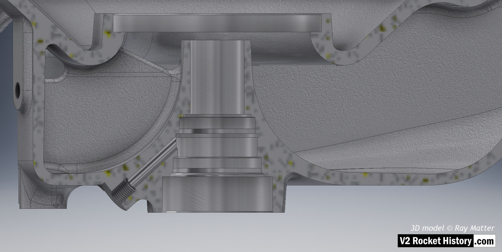
A close-up view of the head fuel valve mounting flange (showing 12 fastener holes). Visible immediately below the top flange are the large connecting holes that allow fuel to flow from the inlet manifold and cooling jacket to the injector space (some brass injector inserts can be seen through the holes) after the head fuel valve is released to be opened by the turbo-pump supply pressure.
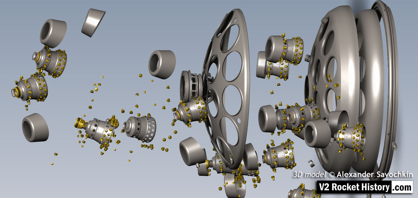
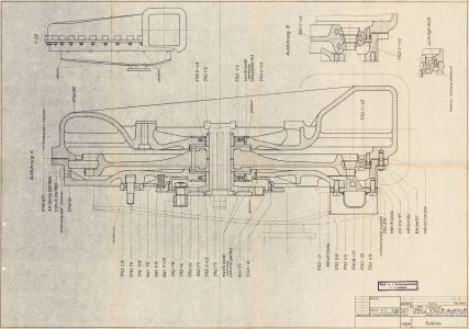
18-pot head Exploded to show 1100+ Parts
18-pot head Exploded to show 1100+ Parts
Exploded view showing some of the 1100 parts required for the complicated 18-pot injector head of the V2 25-ton thrust rocket engine. 3D model by Alexander Savochkin
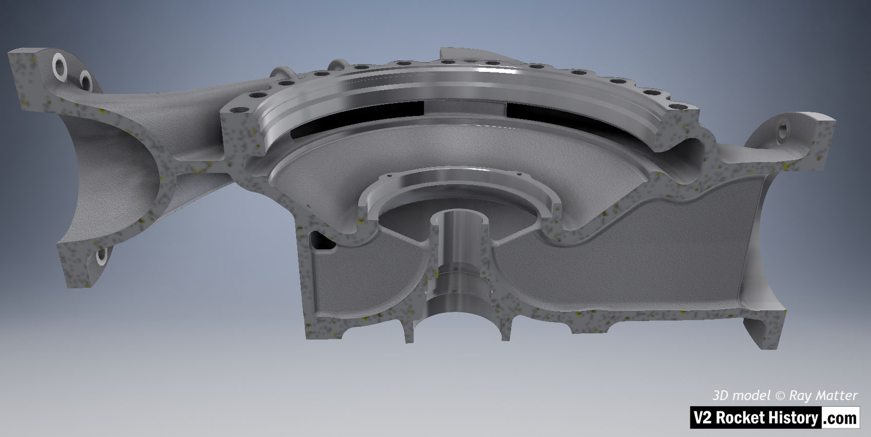
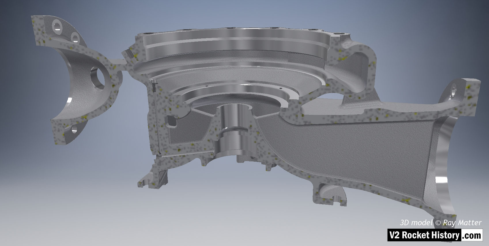
18-pot head: Cutaway 2
18-pot head: Cutaway 2
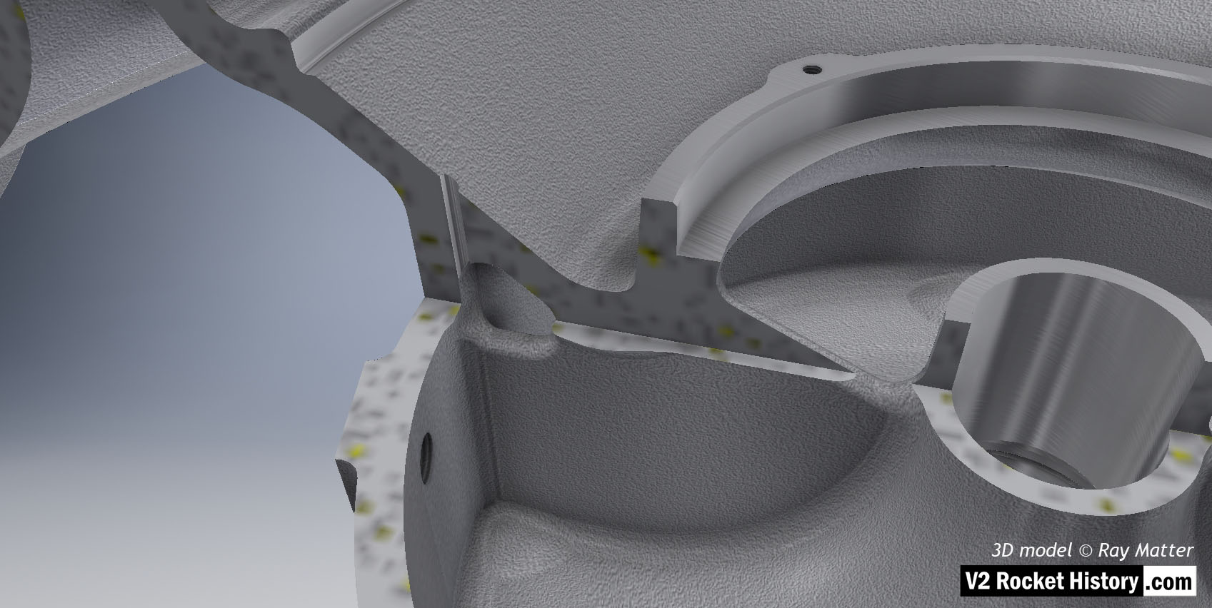
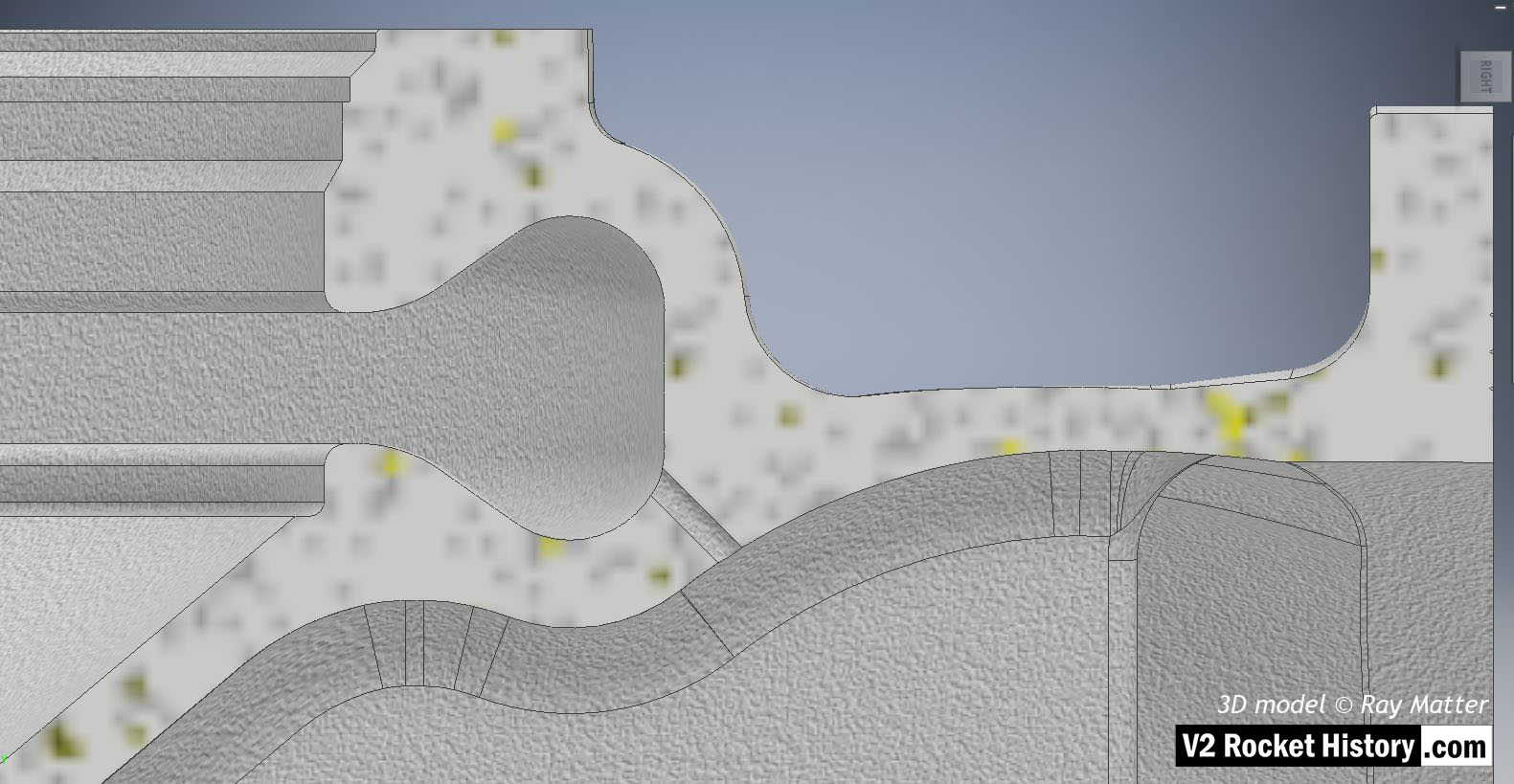
Here the 18-pot head model has been cutaway to show the fuel cooling and fuel delivery spaces. the cooling jacket layer can be seen in the lowermost area of the head – below the centrally positioned fuel valve seat, between each cup at the lowest point, and ruining down toward the first set of veil cooling pores and the topmost coolant distributor ring. Note that the veil cooling system does not communicate with the regenerative cooling jacket and has its own feed pipes drawing fuel from the head injector space and not the cooling space. Visible immediately above the valve seat are the large connecting holes that allow fuel to flow from the inlet manifold and cooling jacket to the injector space after the head fuel valve is released to be opened by the turbo-pump supply pressure. 3D model by Alexander Savochkin
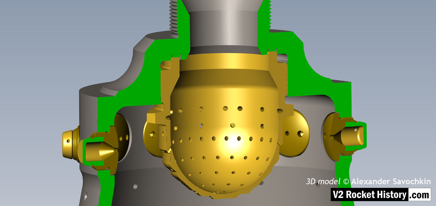
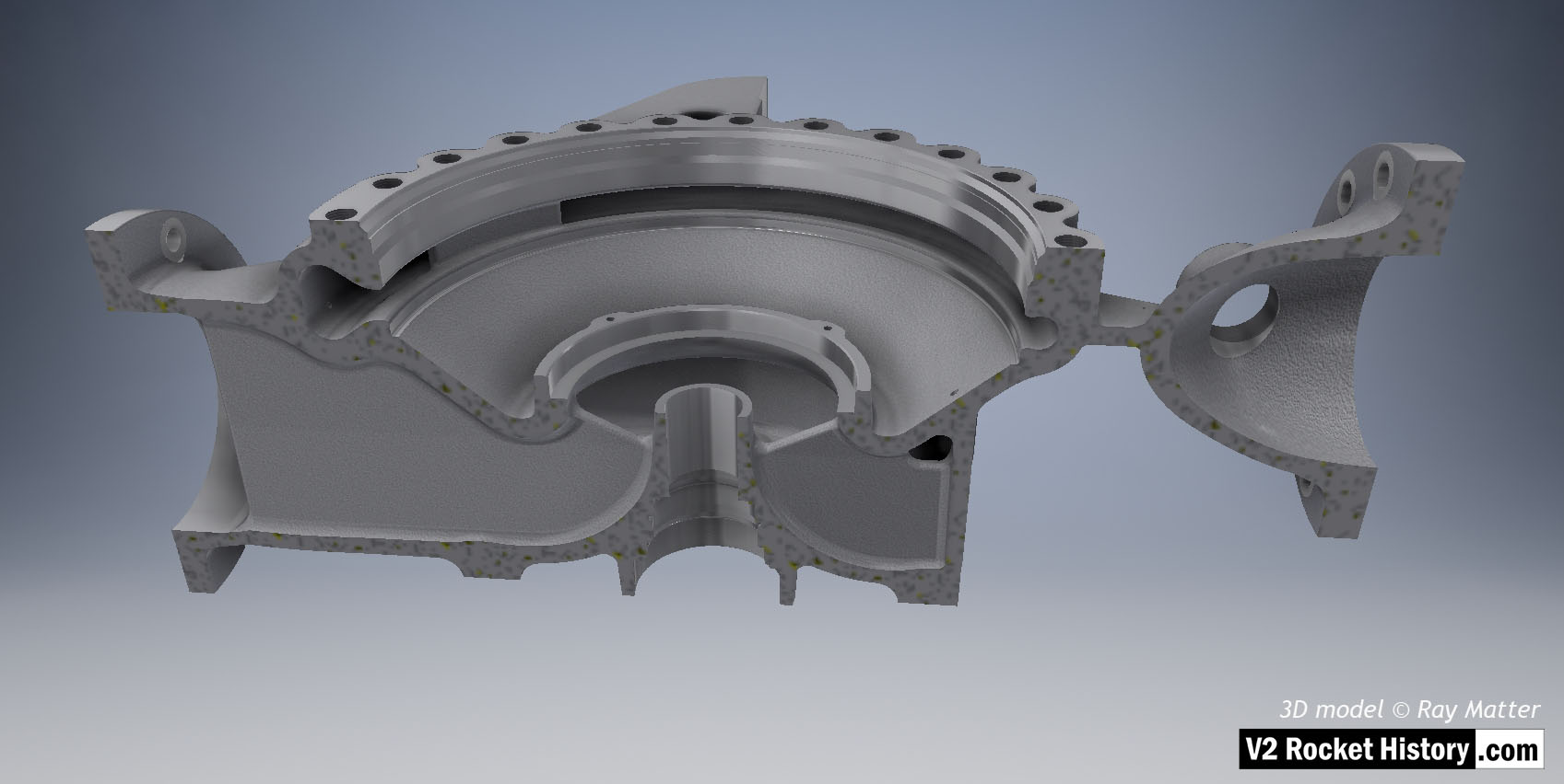
18-pot Cutaway 1
18-pot Cutaway 1
Liquid propellent (LOX and fuel) diffuser cup, showing three rings or echelons (A,D,& E) of brass injector inserts as well as two rows of drilled fuel feed holes. The LOX spray head is shown in the centre. Note the simple ‘shower head or watering can’ design of the LOX diffuser. A sealing washer can be seen fitted between the LOX diffuser and the steel cup. 3D model by Alexander Savochkin

25-Ton aluminium injector pot from 1940/41
25-Ton aluminium injector pot from 1940/41
Relic of prototype A4 25-ton 1940/41 aluminium injector head basket (or pre-chamber) showing 68 copper alloy inserts in 5 rows. The standard configuration would later become 44 inserts in 3 rows 25 2mm diameter drilled holes in two rows situated at row 3 and 4 (counting from nearest the camera). Photo courtesy Host Beck Collection
F1: Fertigungshalle Eins

Bomb damaged F1 factory 1945
Bomb damaged F1 factory 1945
Bomb damaged F1 factory 1945. The huge V2 rocket factory shown badly damaged by air attack at the end of the war in May 1945
Equipment bays
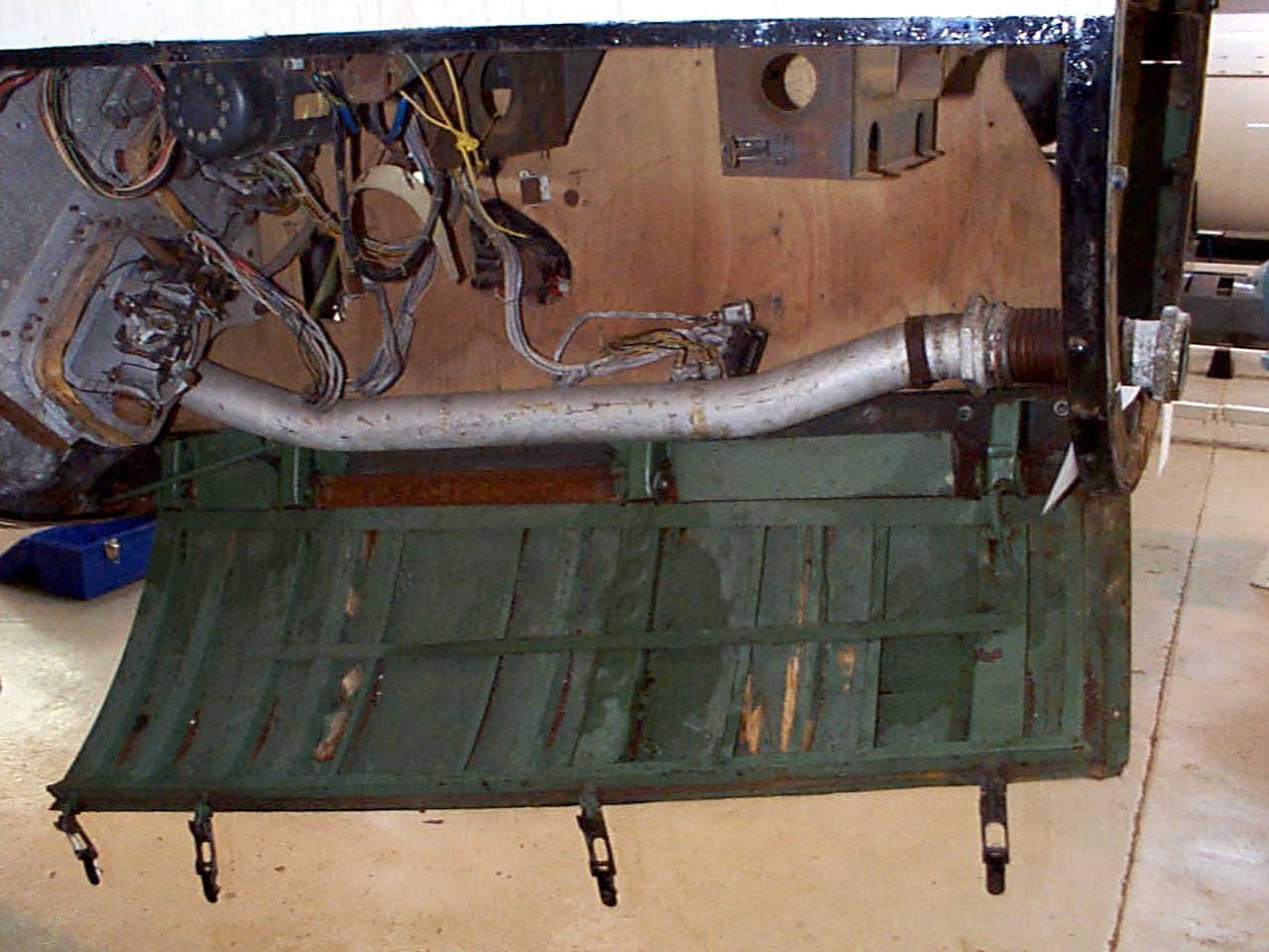
Control compartment 3
Control compartment 3
Control compartments 3 showing gyro mounting platform with two gyros and DC motor driven 3 phase AC voltage generator. The alcohol tank pressurisation pipe is also shown running through the equipment bay (large silver coloured pipe). Image copyright Imperial War Museum
| Album | Equipment bays |
| Category | Guidence |

Ernst Steinhoff
Ernst Steinhoff
Ernst Steinhoff, chief of the BSM workshop (Guidance and Control) in the development works Peenemunde.
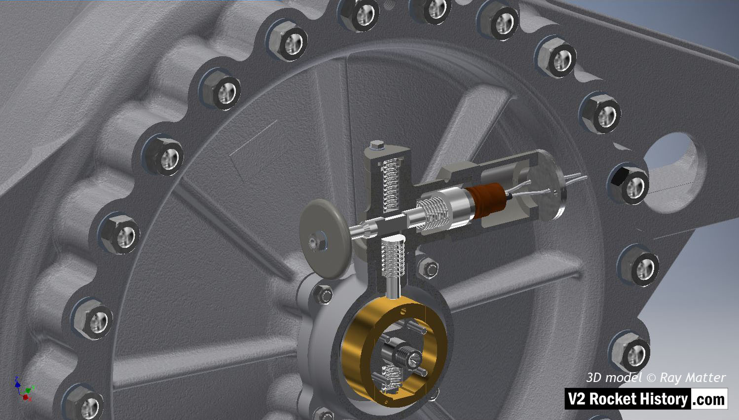
Gear pump detail showing ceramic insulator with nichrome element
Gear pump detail showing ceramic insulator with nichrome element
Hydraulic gear pump with close up detail showing ceramic heater element insulators with flat, possibly nichome, metal strip element threaded through them. This oil heating system was designed to maintain a specific viscosity of the oil regardless of environmental temperature, to better maintain oil flow rates and thus pump efficiency. The heating system is found only rarely on surviving relics.
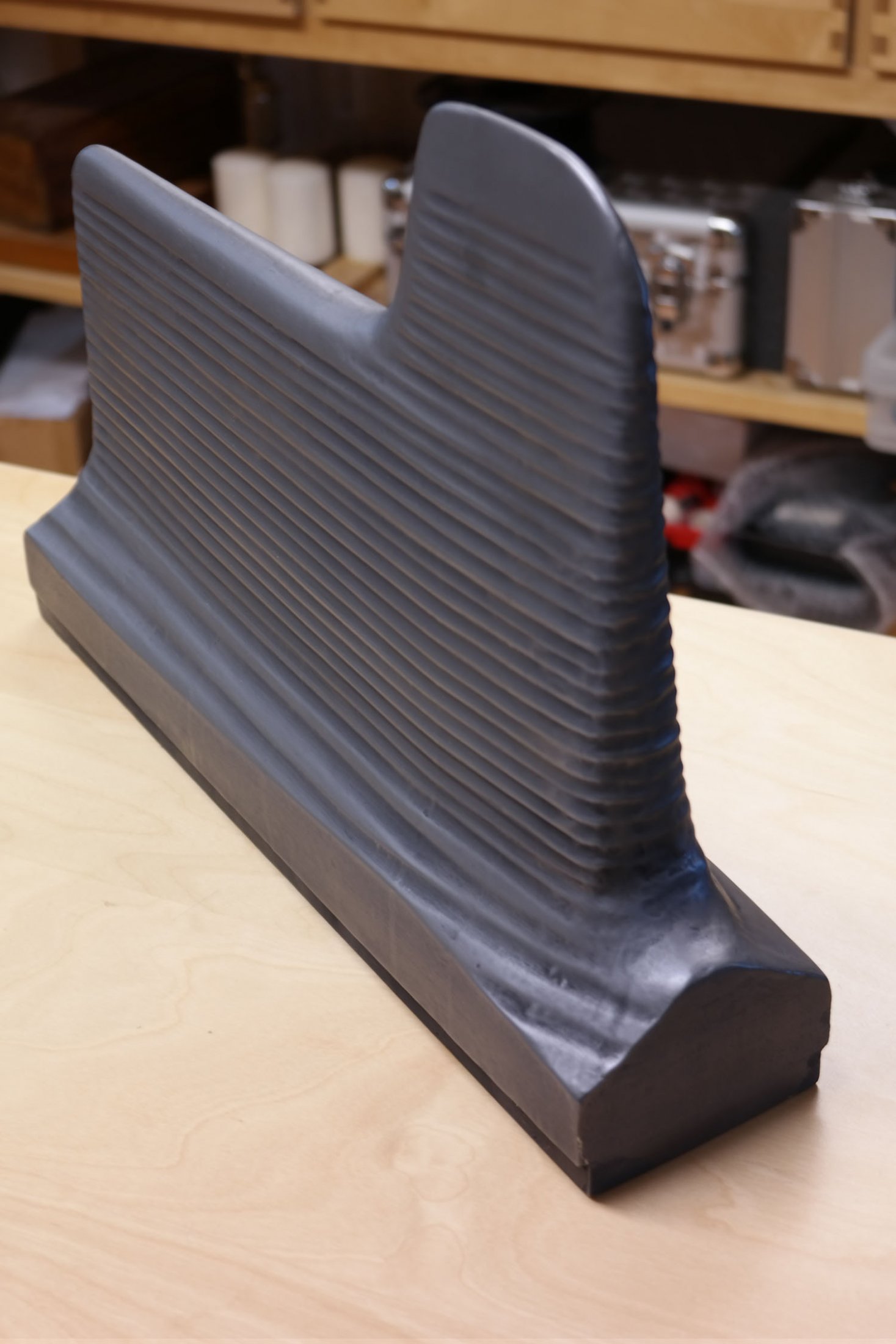
Graphite jet vane replica
Graphite jet vane replica
V2 missile graphite jet vane defector replica made for V2 Rocket History.
Graphite vane rocket jet deflector replica
Graphite vane rocket jet deflector replica
V2 missile graphite jet vane defector replica made for V2 Rocket History. This accurate replica shows the distinctive pantograph mill tool ‘witness’ marks well.
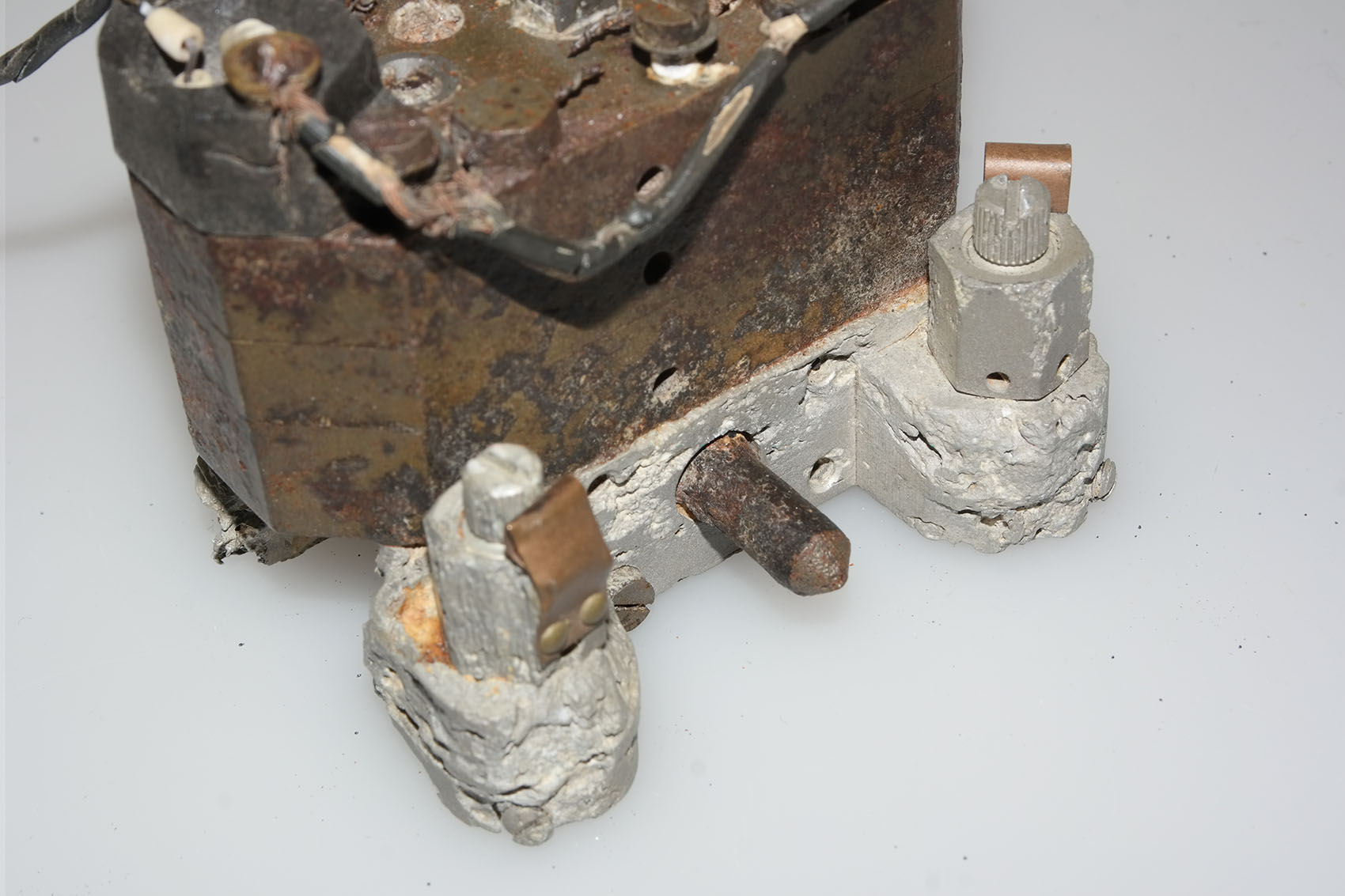
Hydraulic gear pump detail
Hydraulic gear pump detail
Close-up of Askania gear pump relic with oil heaters. This picture shows an unusual feature on the otherwise normal cast aluminium base of this gear pump. The knurled knob positioned between the oil flow balance adjusters has a purpose that is unknown to us. The two oil-flow balance adjuster valves visible in the picture have slot head adjuster screws and you can also see the knurled circumference on each screw. This parallel knurling is engaged by a crease formed in the facing surface of the copper spring strips. The function of these strips is to create tactile feedback that the technician making the adjustment can feel in the handle of the screwdriver. This was done because the gear pump needed to be adjusted in a dark and narrowly confined space.
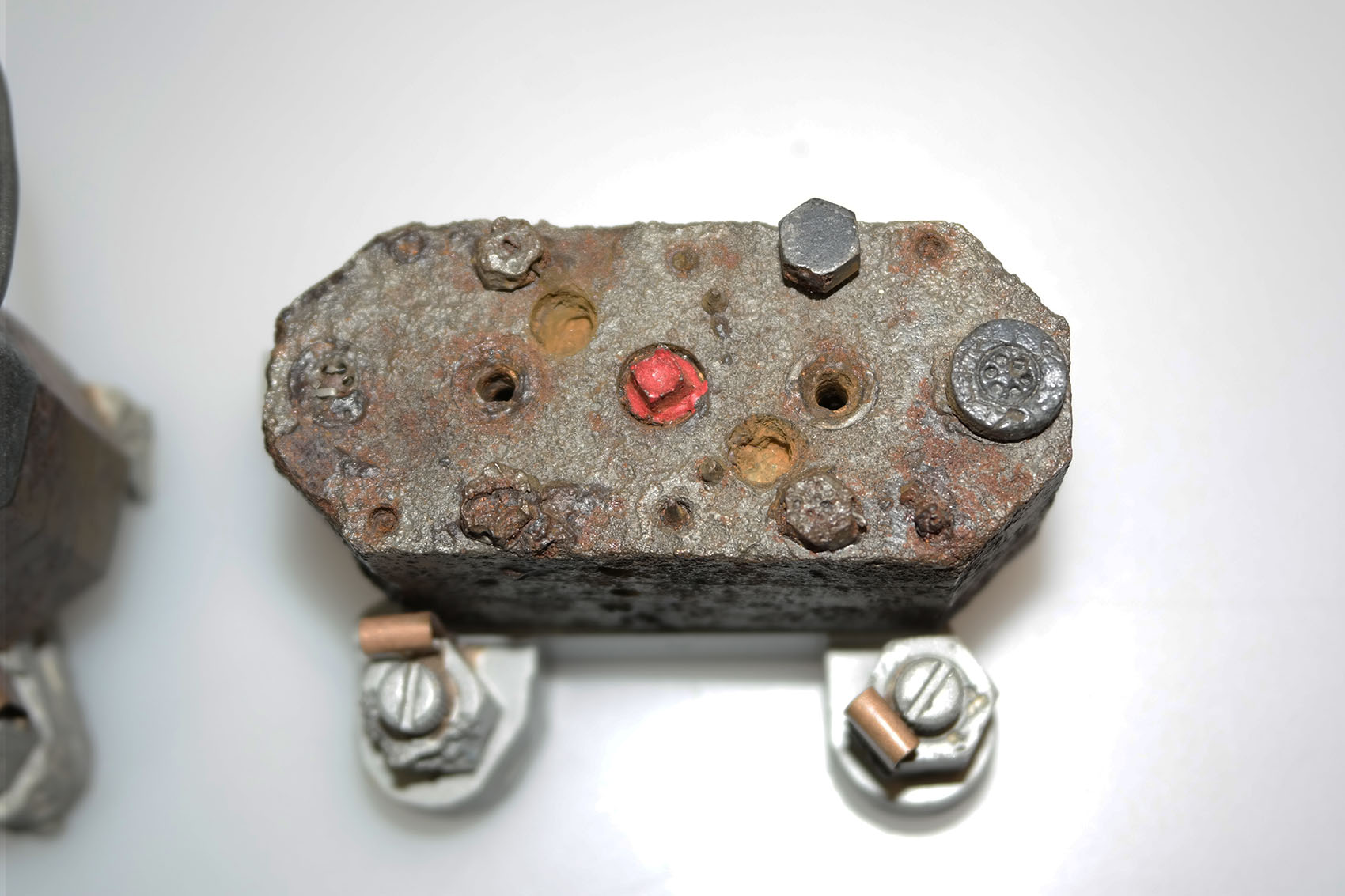
Gear pump showing flow adjusters and ceramic heater elements
Gear pump showing flow adjusters and ceramic heater elements
Gear pump showing flow adjusters (two slot head screws nearest bottom of picture) and ceramic heater elements situated at each end of the block. The square drive shaft coupler (corroded but still identifiable) has been highlighted in red paint. The open holes either side are the main control valve guides. The copper spring strips visible on each oil flow adjuster provide locking and tactile feed-back for the adjusting process. This relic was recovered from Usedom island.
Missile guidance equipment
Images of guidance and missile control equiment
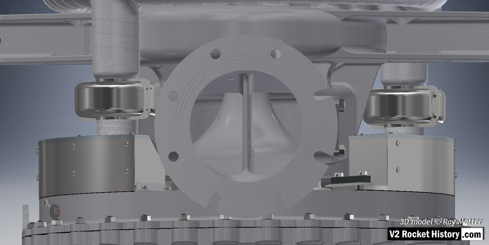
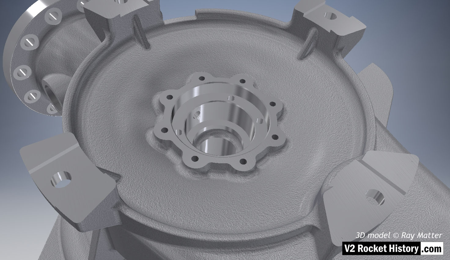
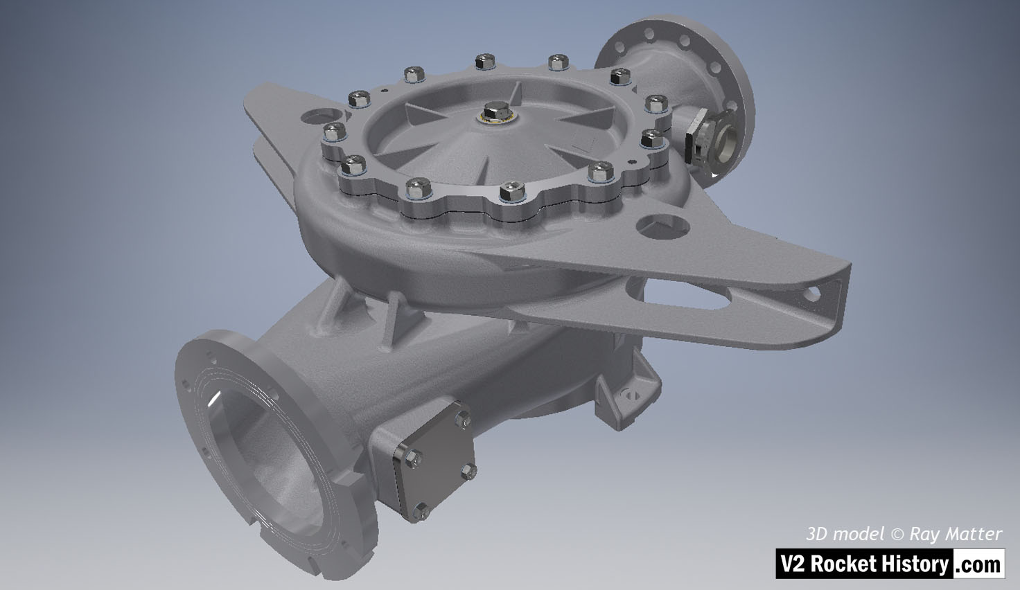
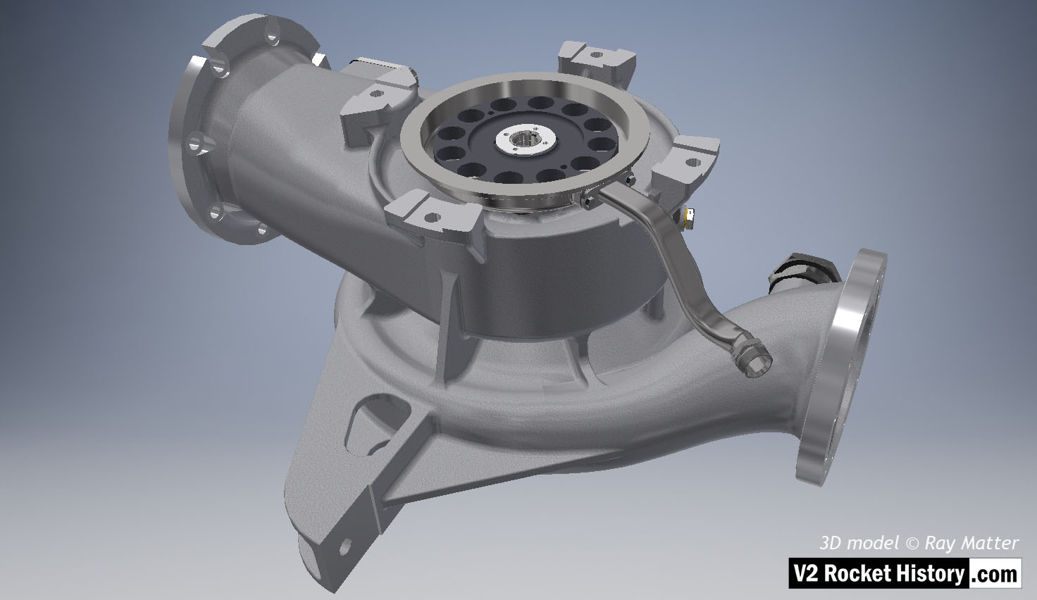
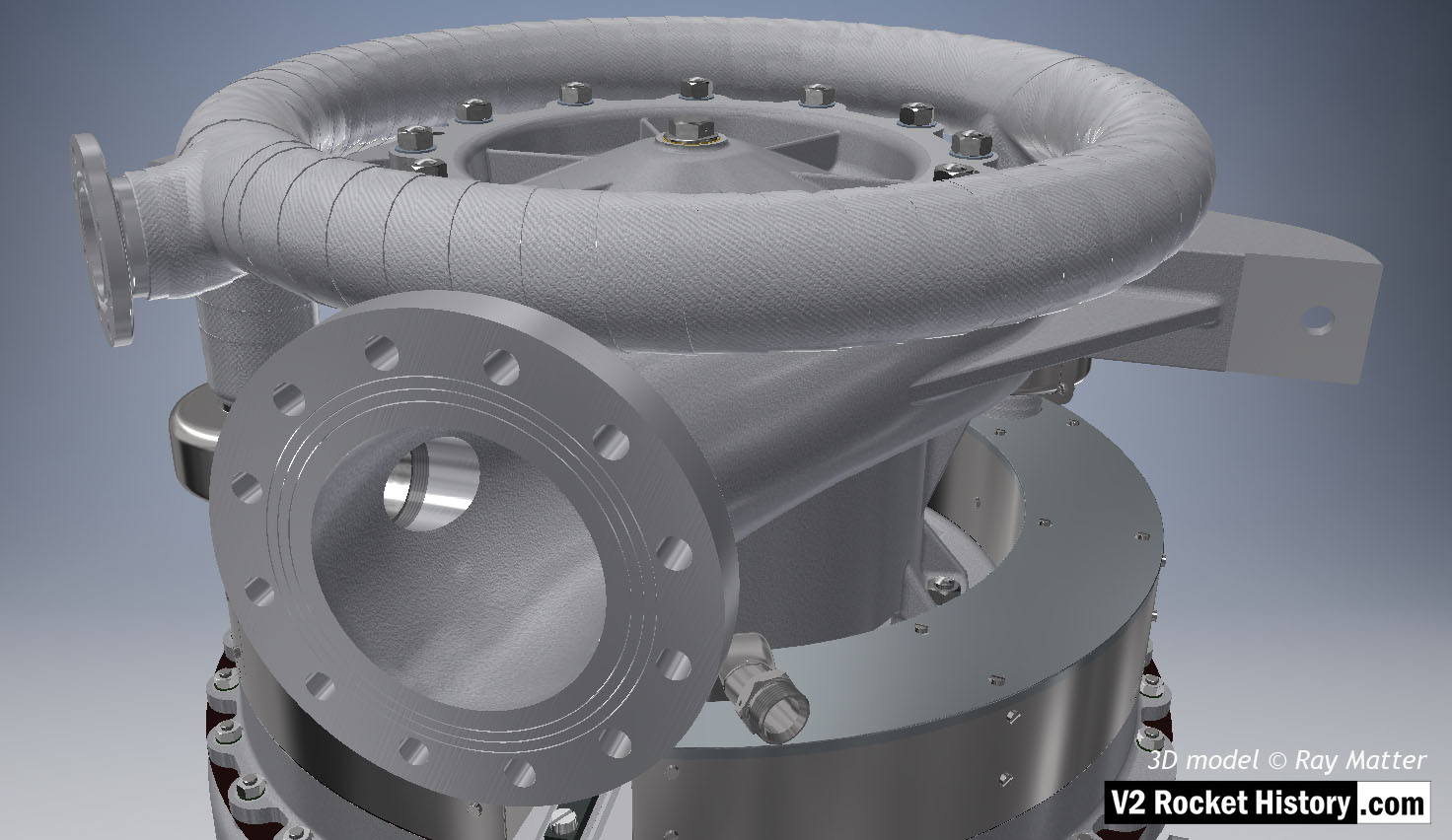
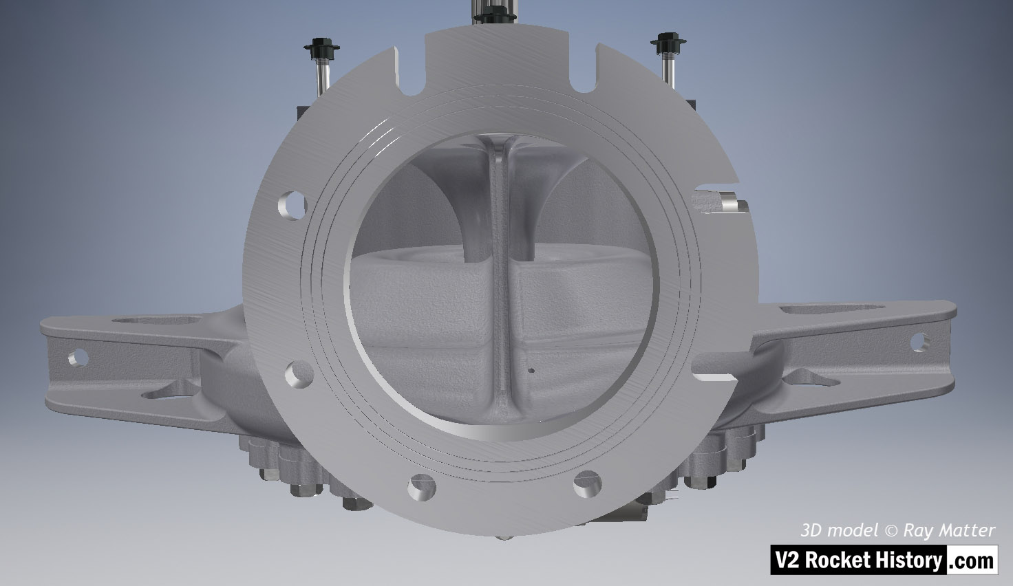
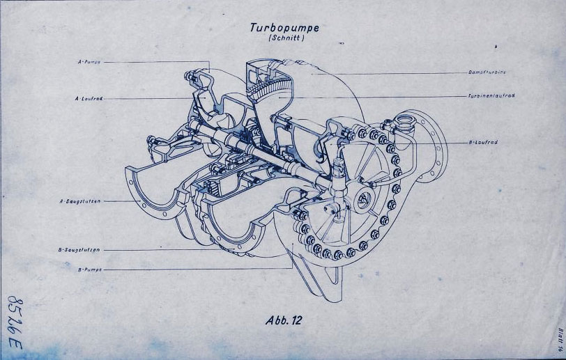
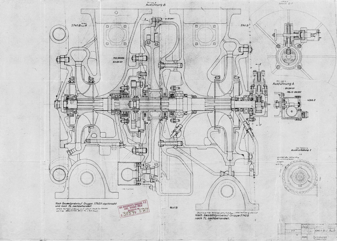
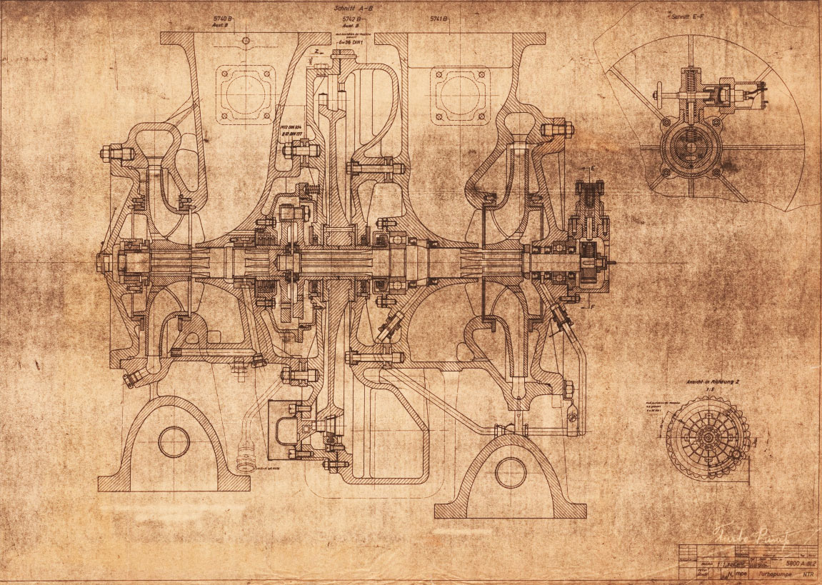
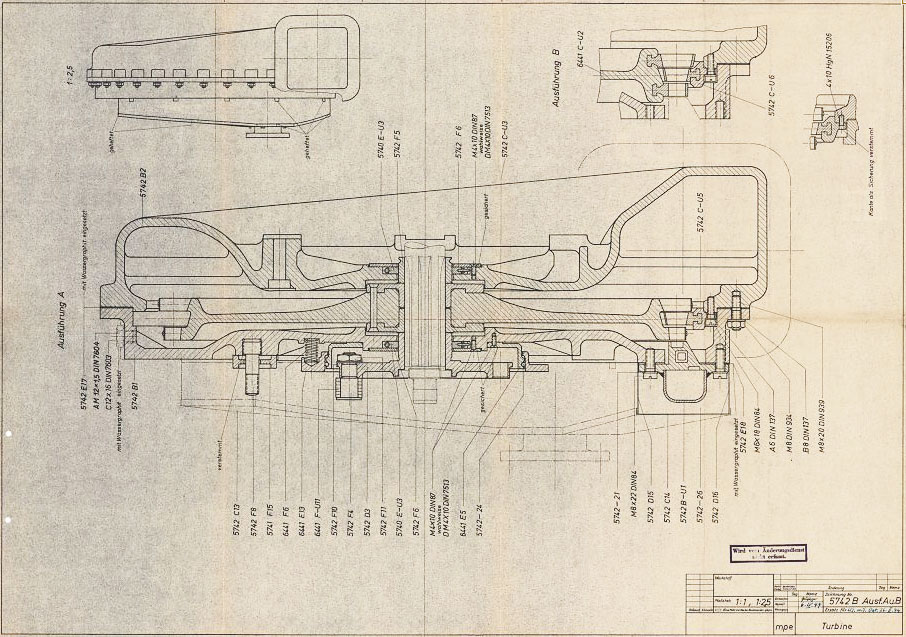
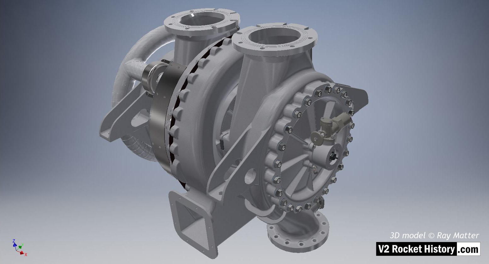
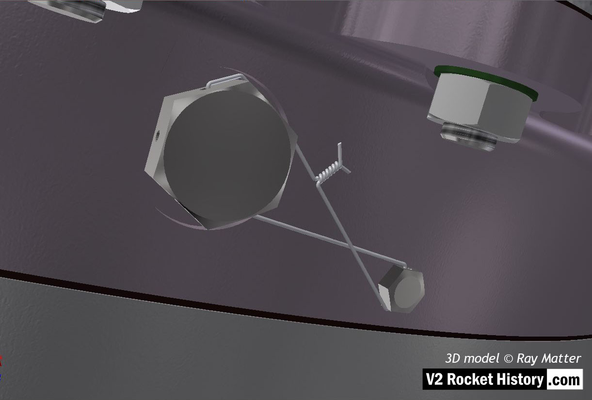
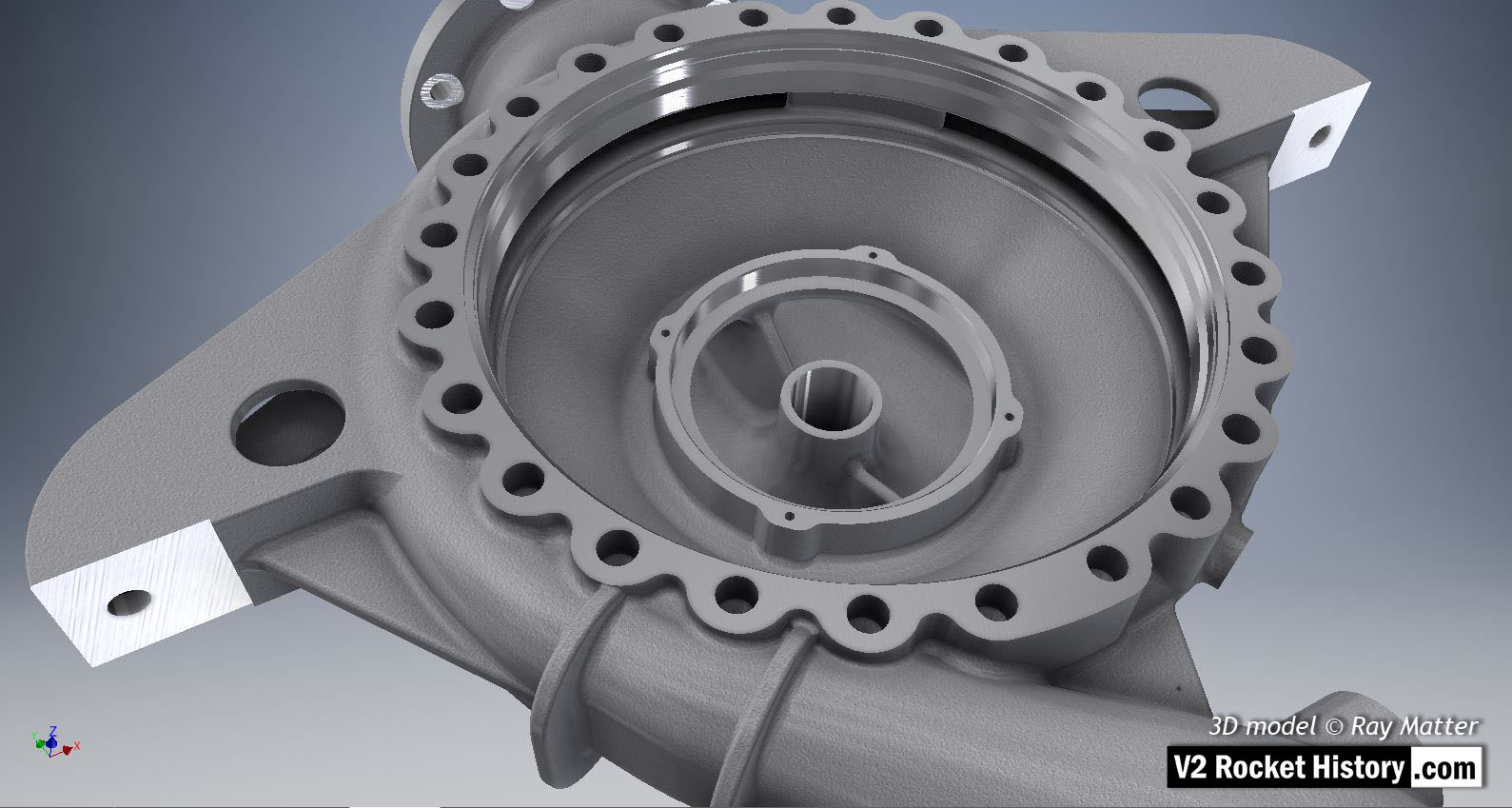

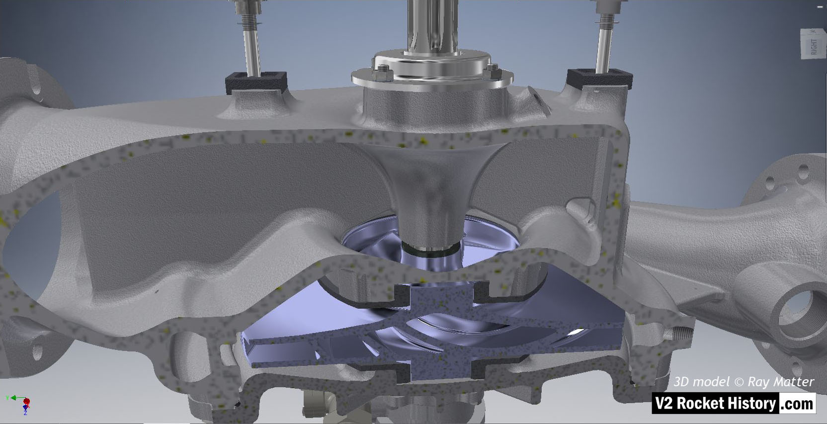
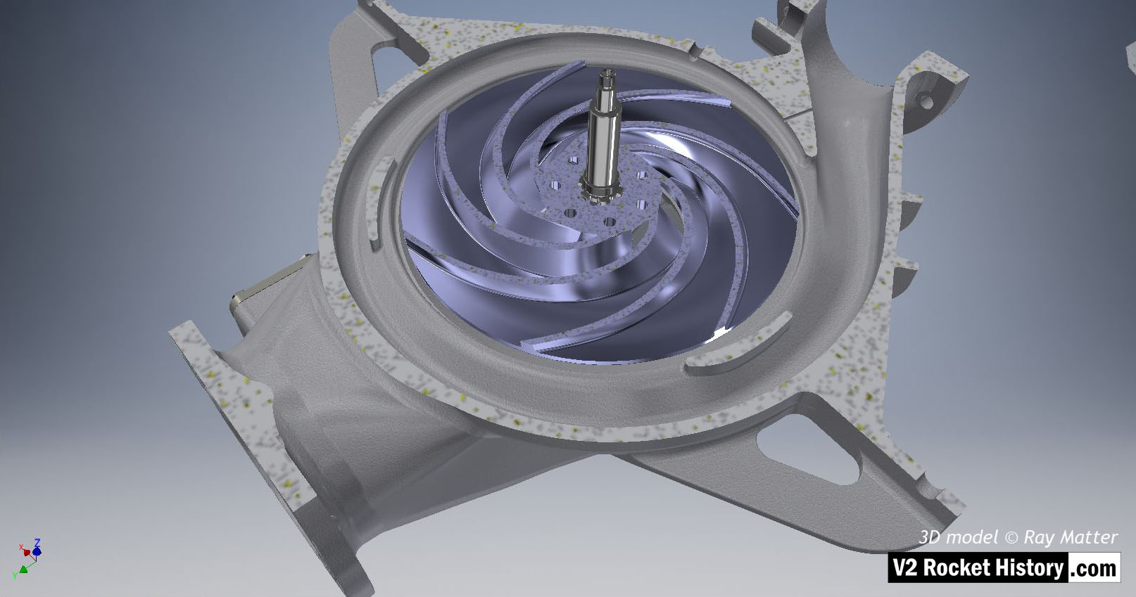
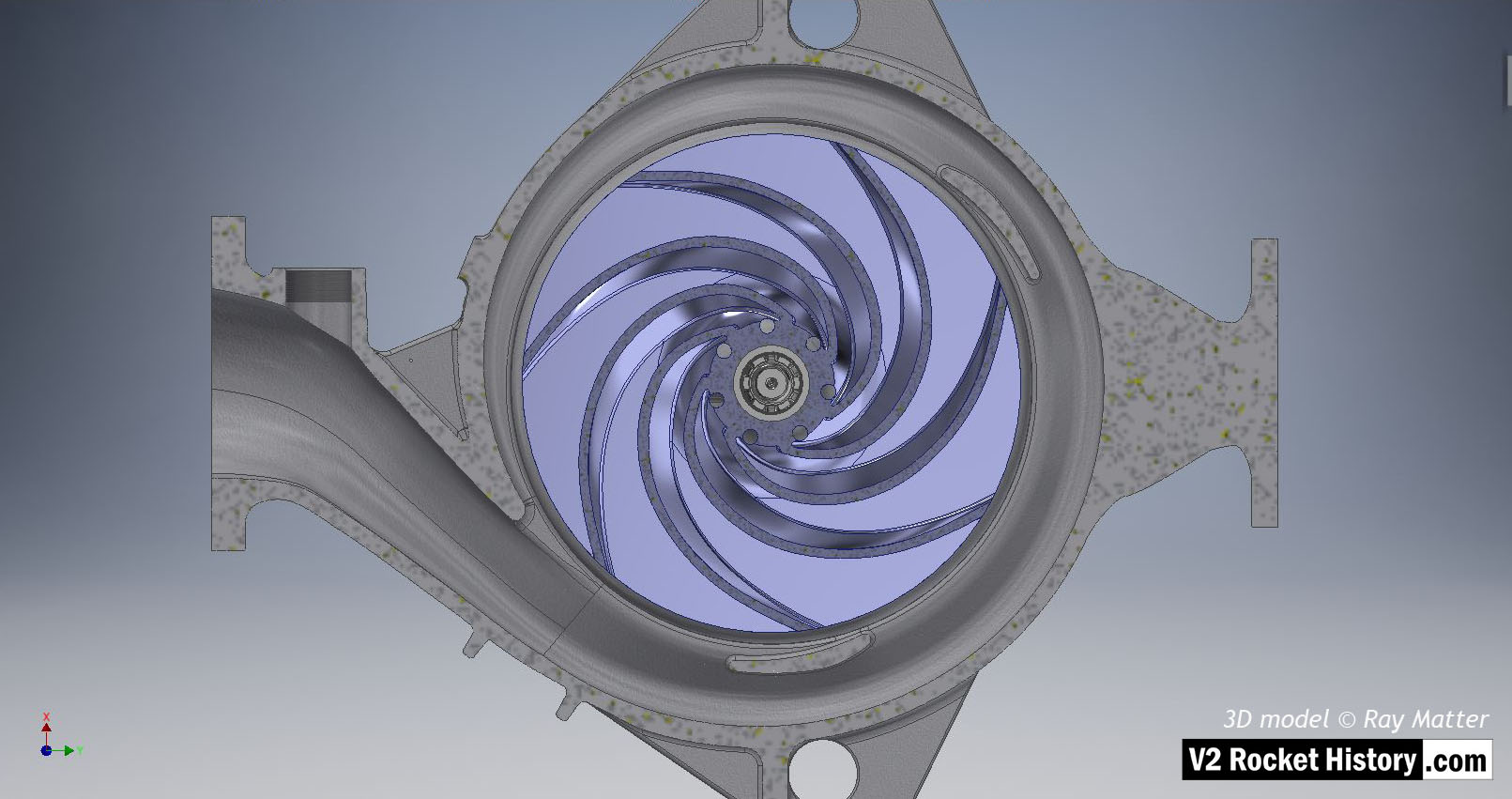
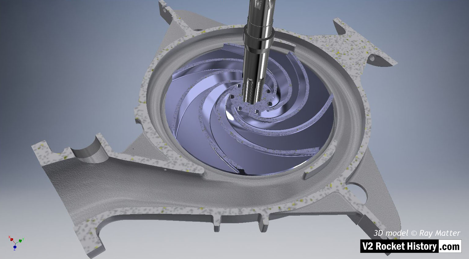
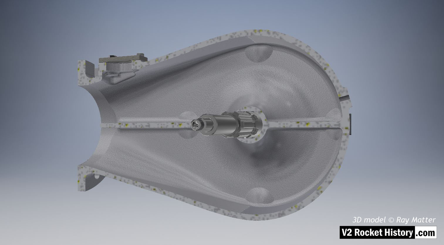
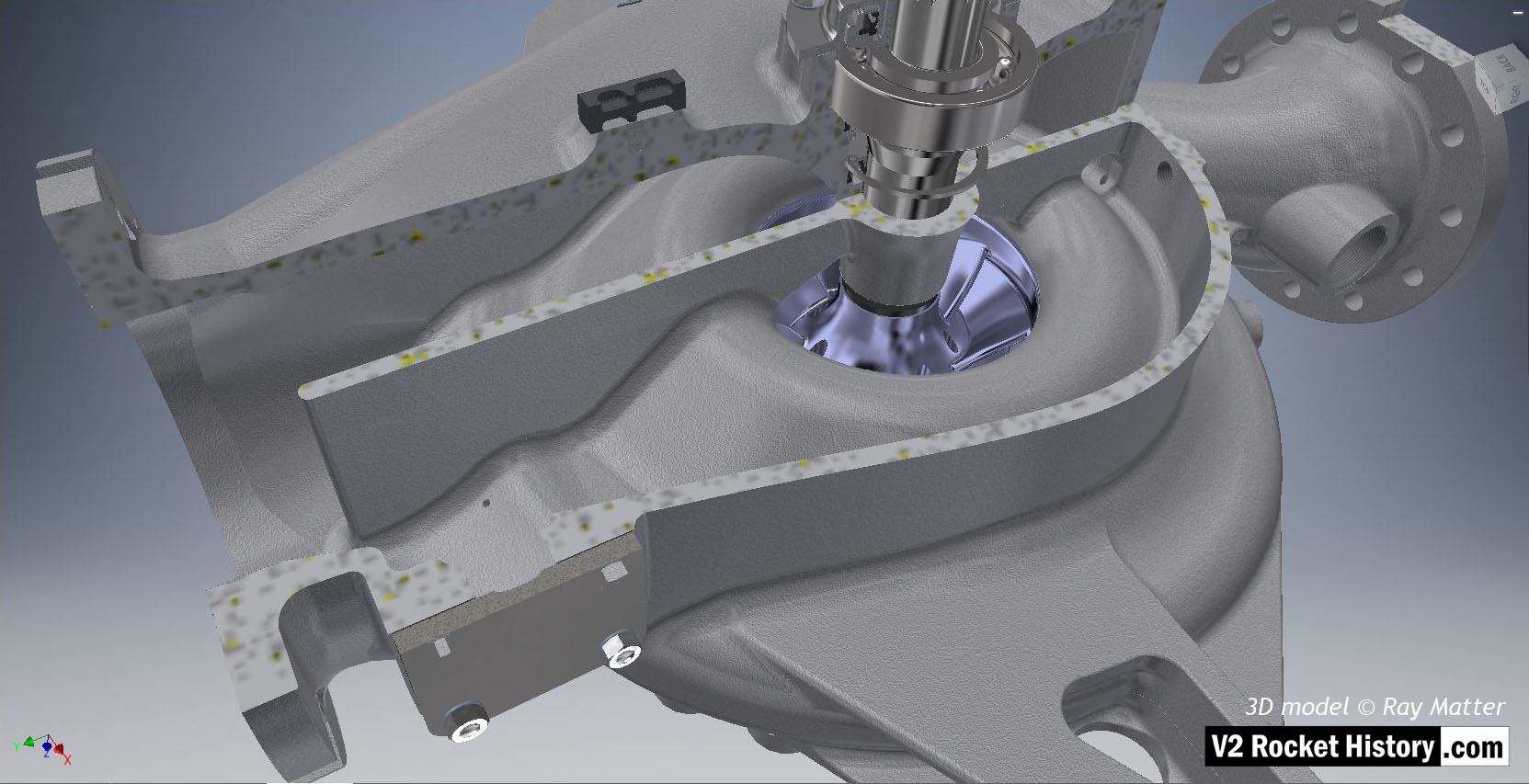
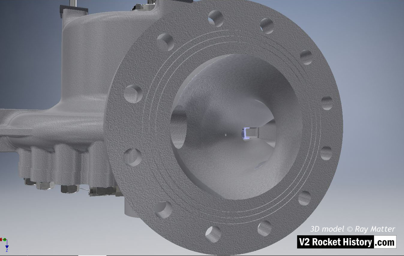
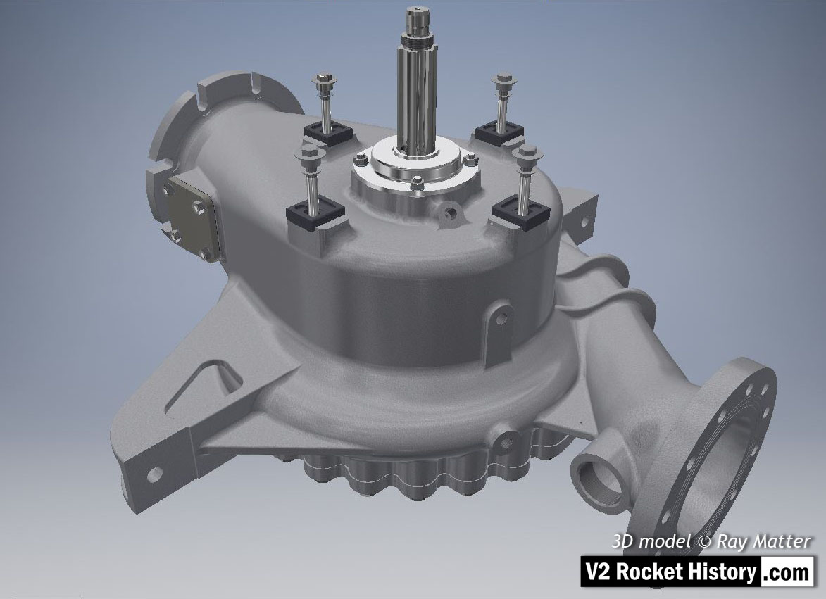
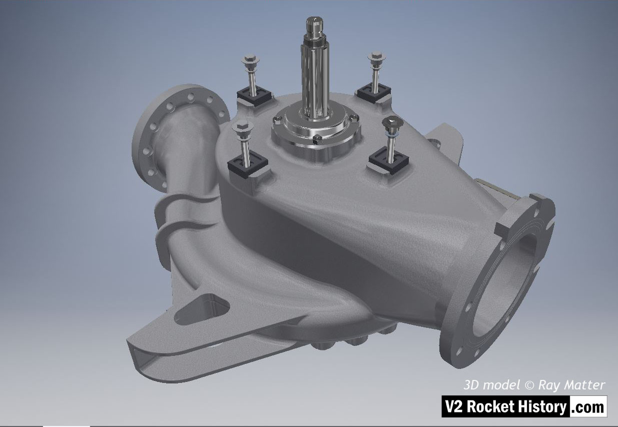
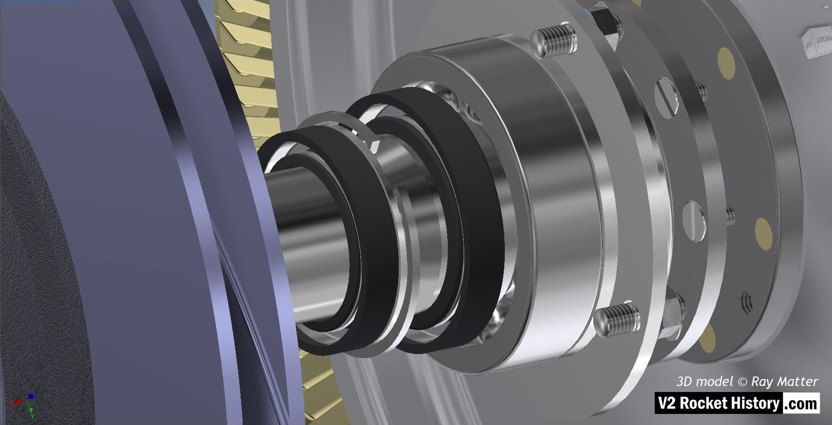
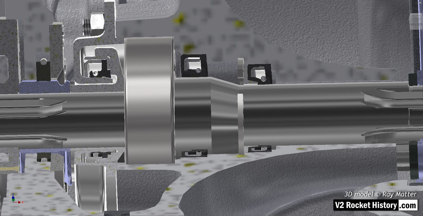
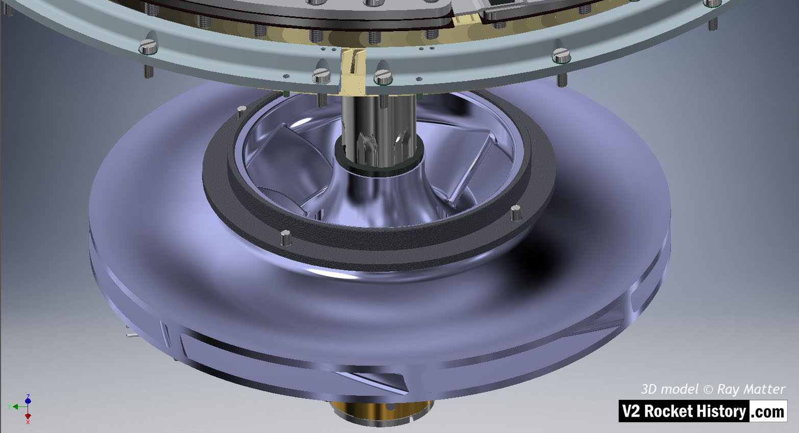
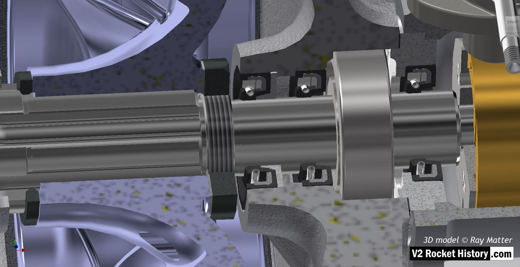
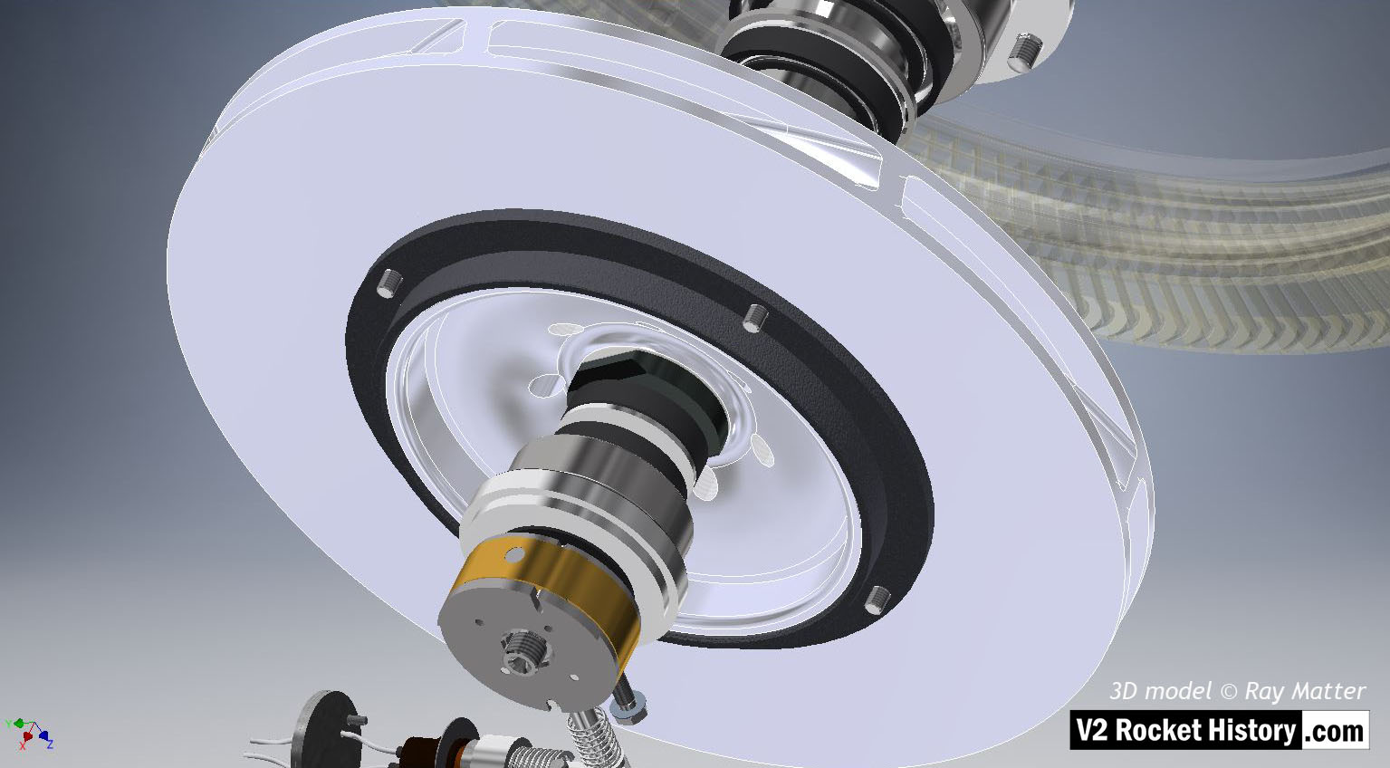
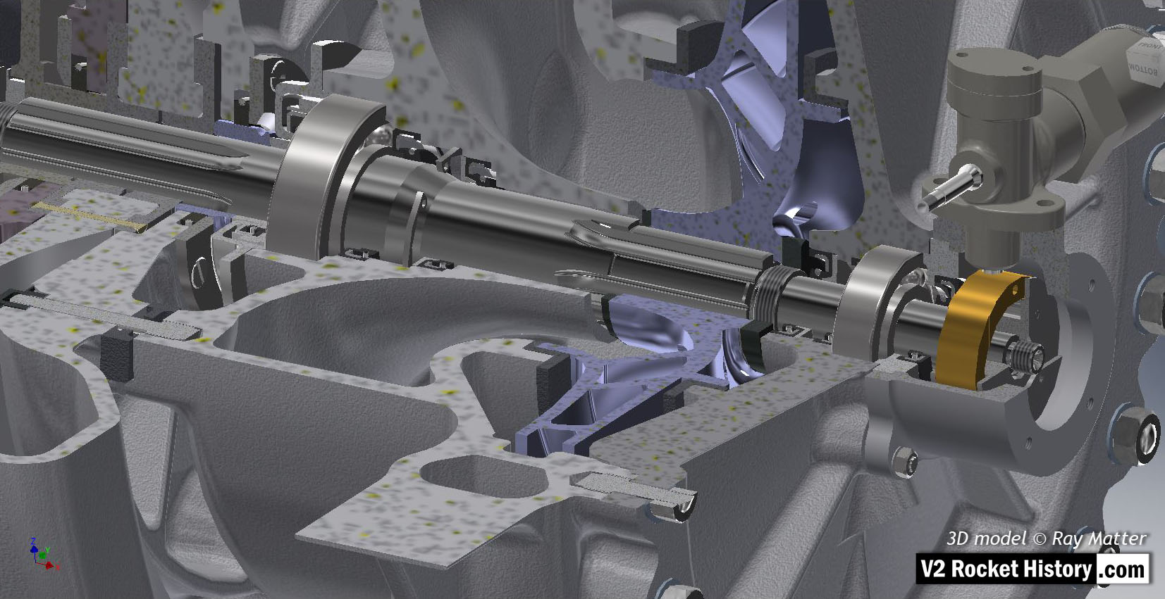
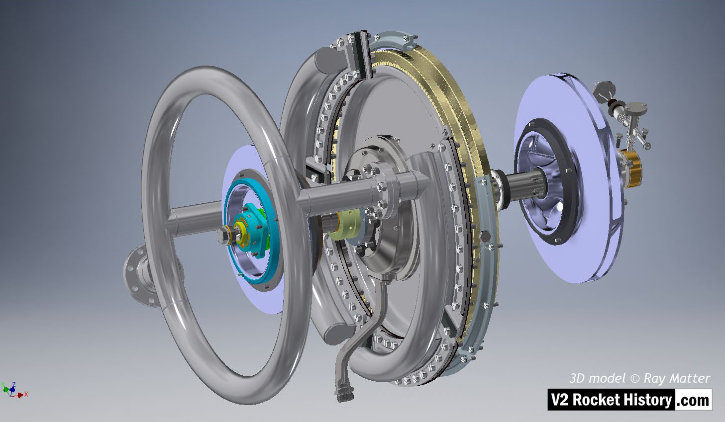
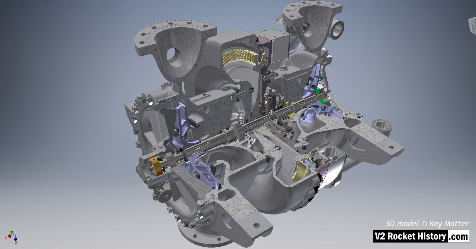
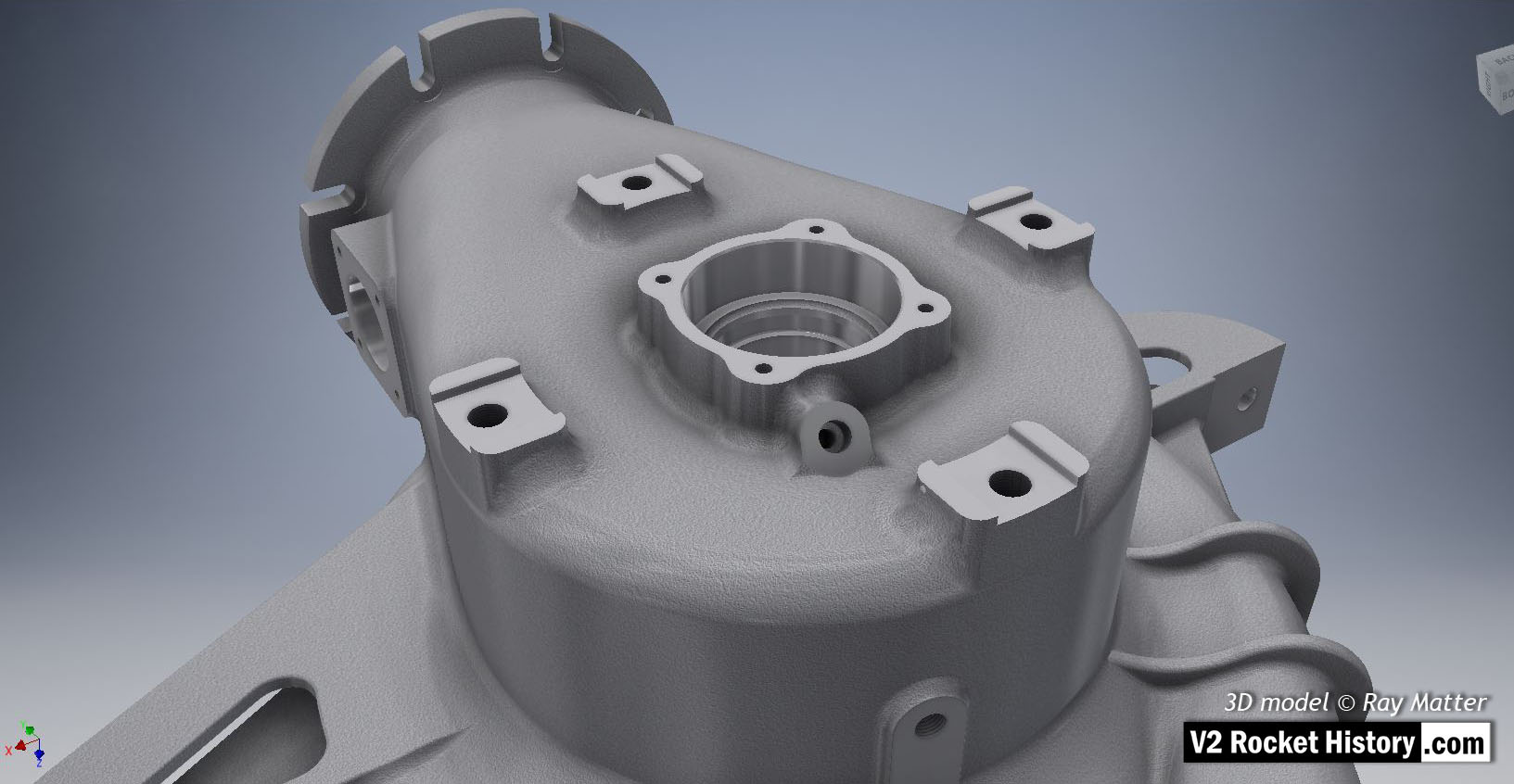
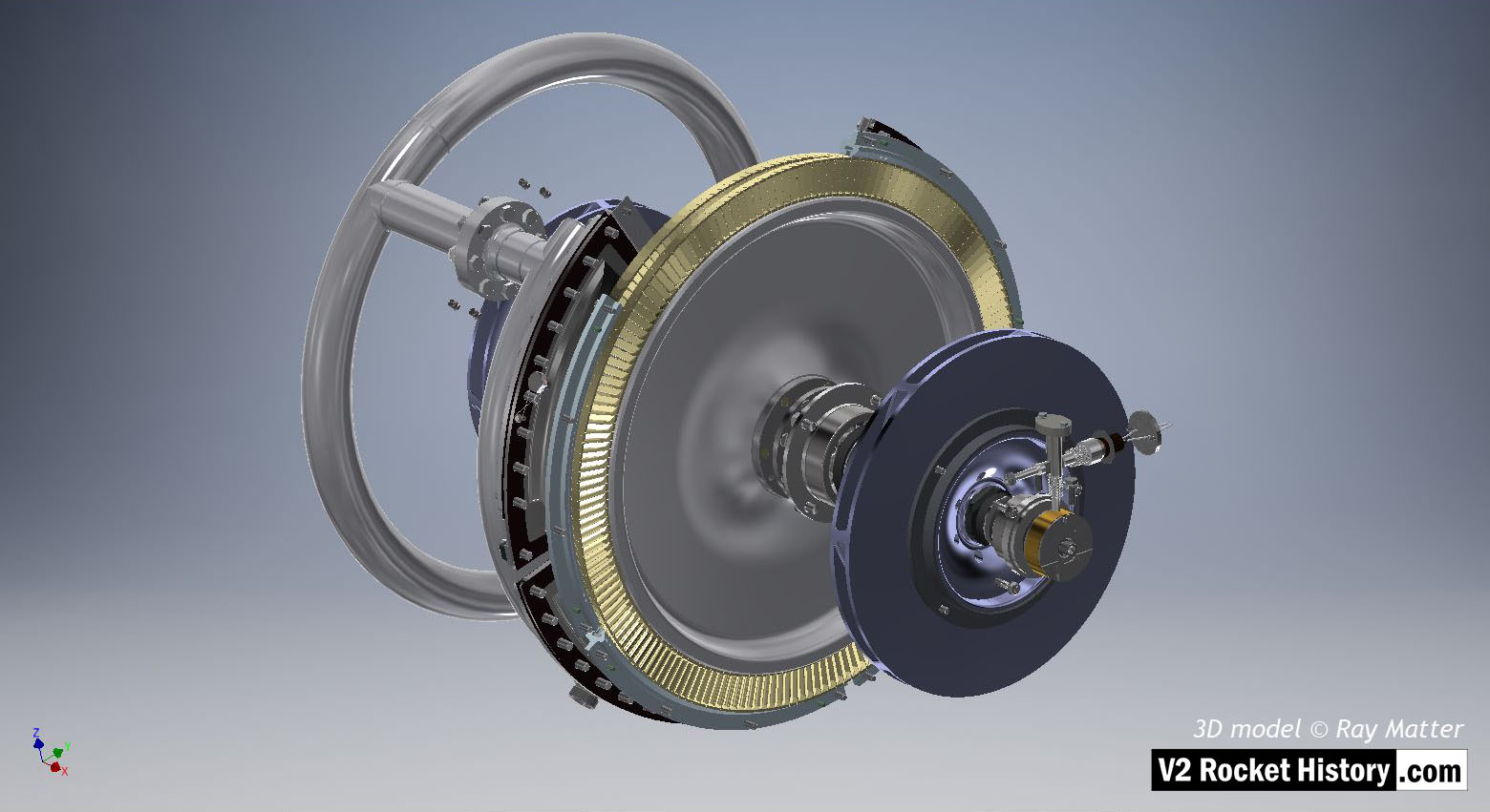
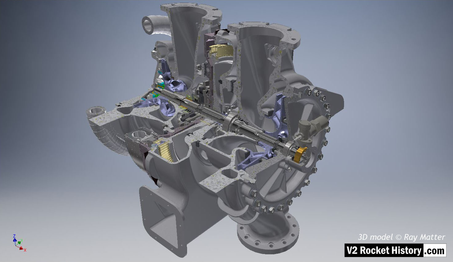
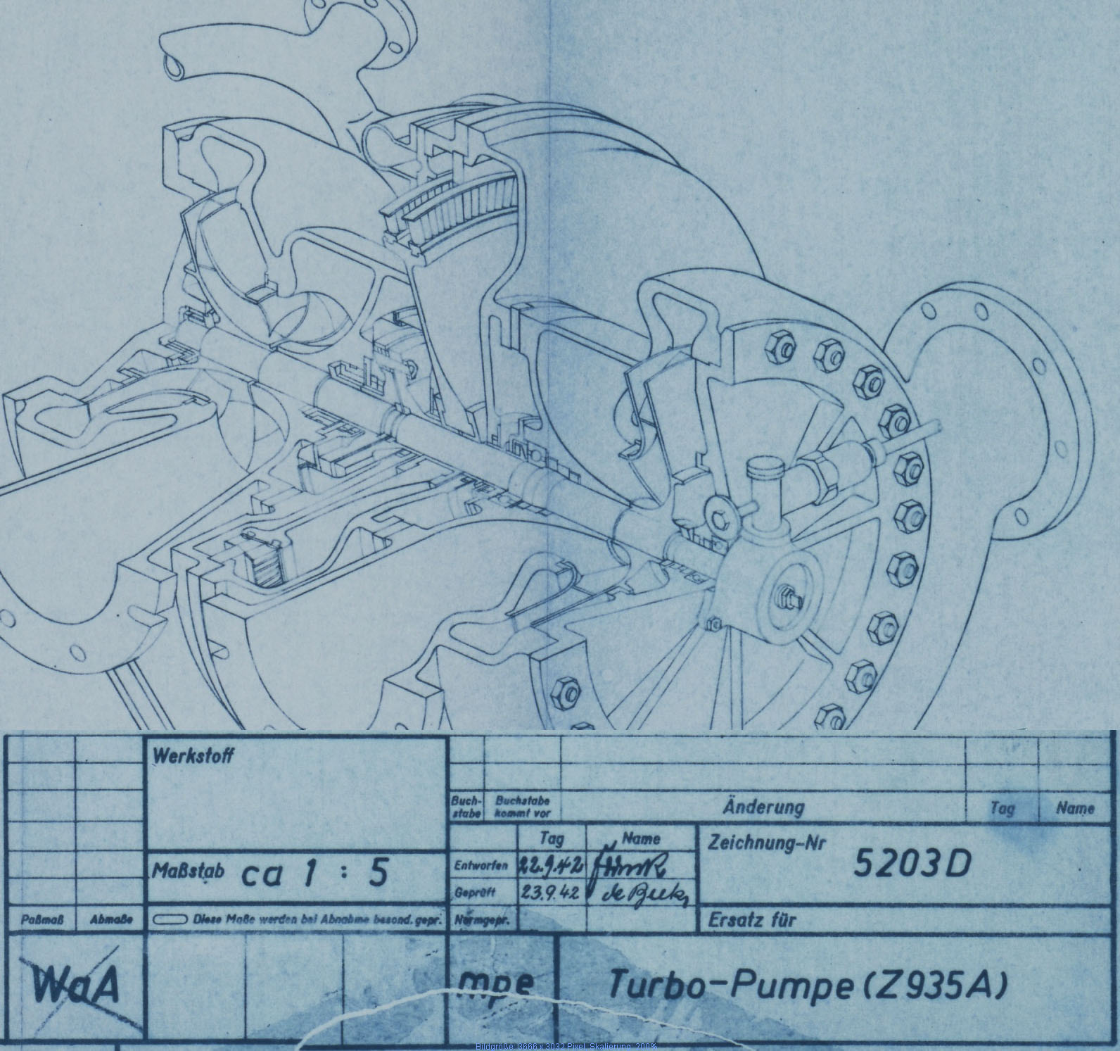
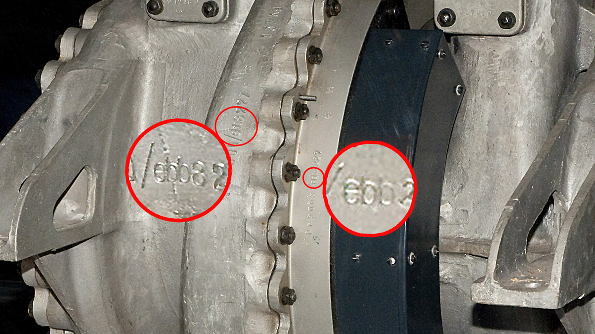
Turbo-pump


Description
Close-up of turbine showing steel case with lid removed to show steam inlet ring manifold. The thin steel case that fits around the steam manifold mating flanges is clearly shown as is the wire restraint fastener locking system (see close-up in gallery). 3D model by Ray Matter
Location
