

Archives: Gmedia Albums


The Enigmas
Control compartment 3
Control compartment 3
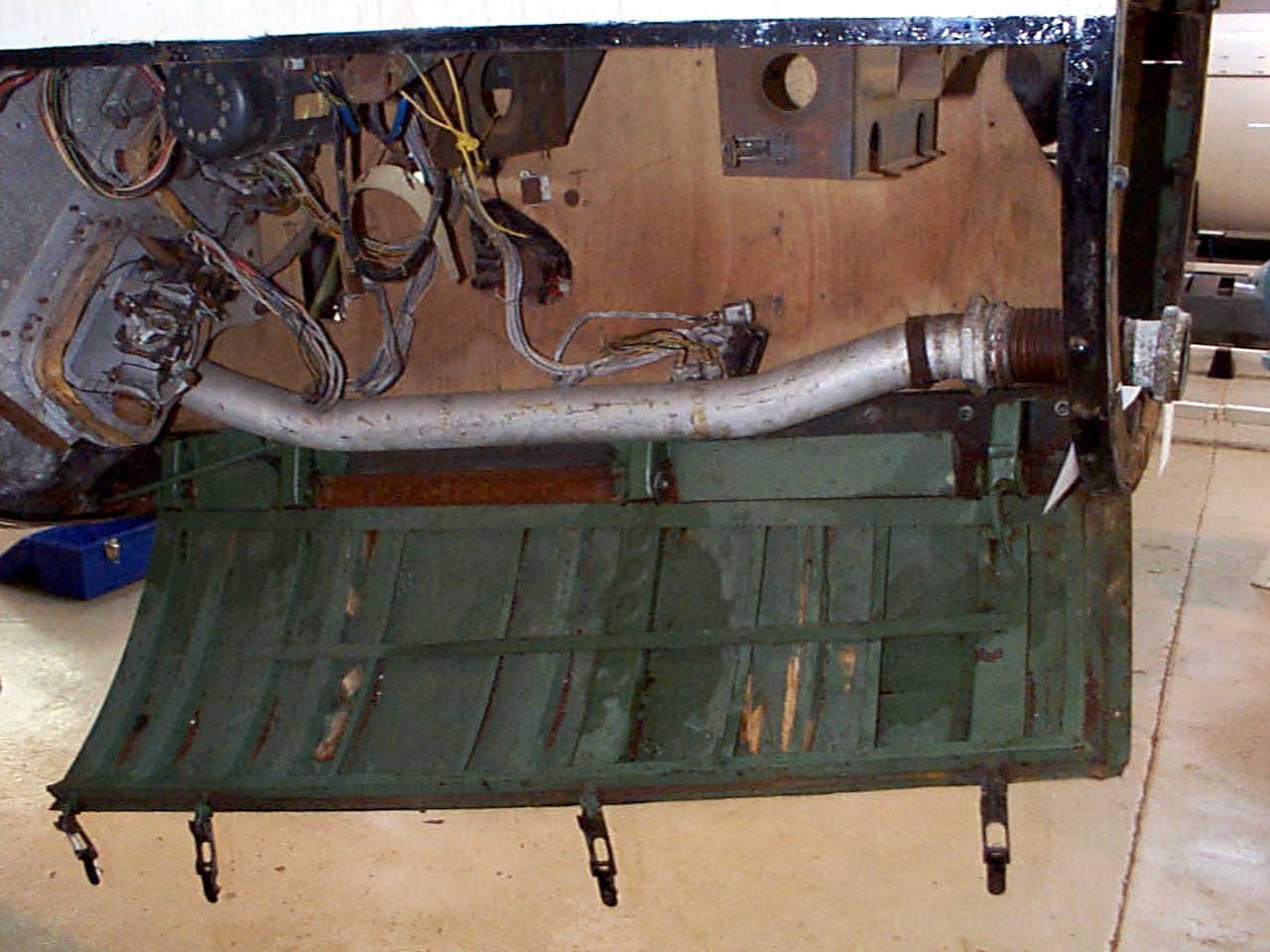
Control compartments 3 showing gyro mounting platform with two gyros and DC motor driven 3 phase AC voltage generator. The alcohol tank pressurisation pipe is also shown running through the equipment bay (large silver coloured pipe). Image copyright Imperial War Museum
| Album | Equipment bays |
| Category | Guidence |
Ernst Steinhoff
Ernst Steinhoff
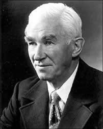
Ernst Steinhoff, chief of the BSM workshop (Guidance and Control) in the development works Peenemunde.
Gear pump detail showing ceramic insulator with nichrome element
Gear pump detail showing ceramic insulator with nichrome element
Hydraulic gear pump with close up detail showing ceramic heater element insulators with flat, possibly nichome, metal strip element threaded through them. This oil heating system was designed to maintain a specific viscosity of the oil regardless of environmental temperature, to better maintain oil flow rates and thus pump efficiency. The heating system is found only rarely on surviving relics.
Graphite jet vane replica
Graphite jet vane replica
V2 missile graphite jet vane defector replica made for V2 Rocket History.
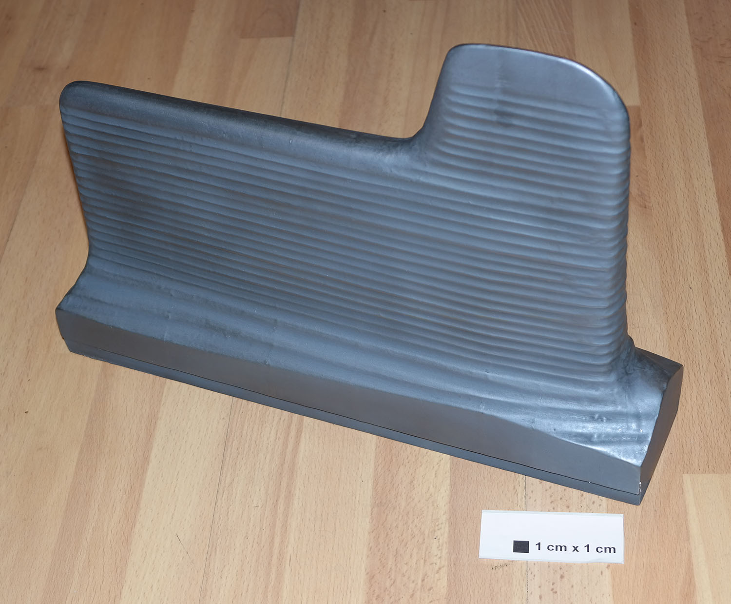
Graphite vane rocket jet deflector replica
Graphite vane rocket jet deflector replica
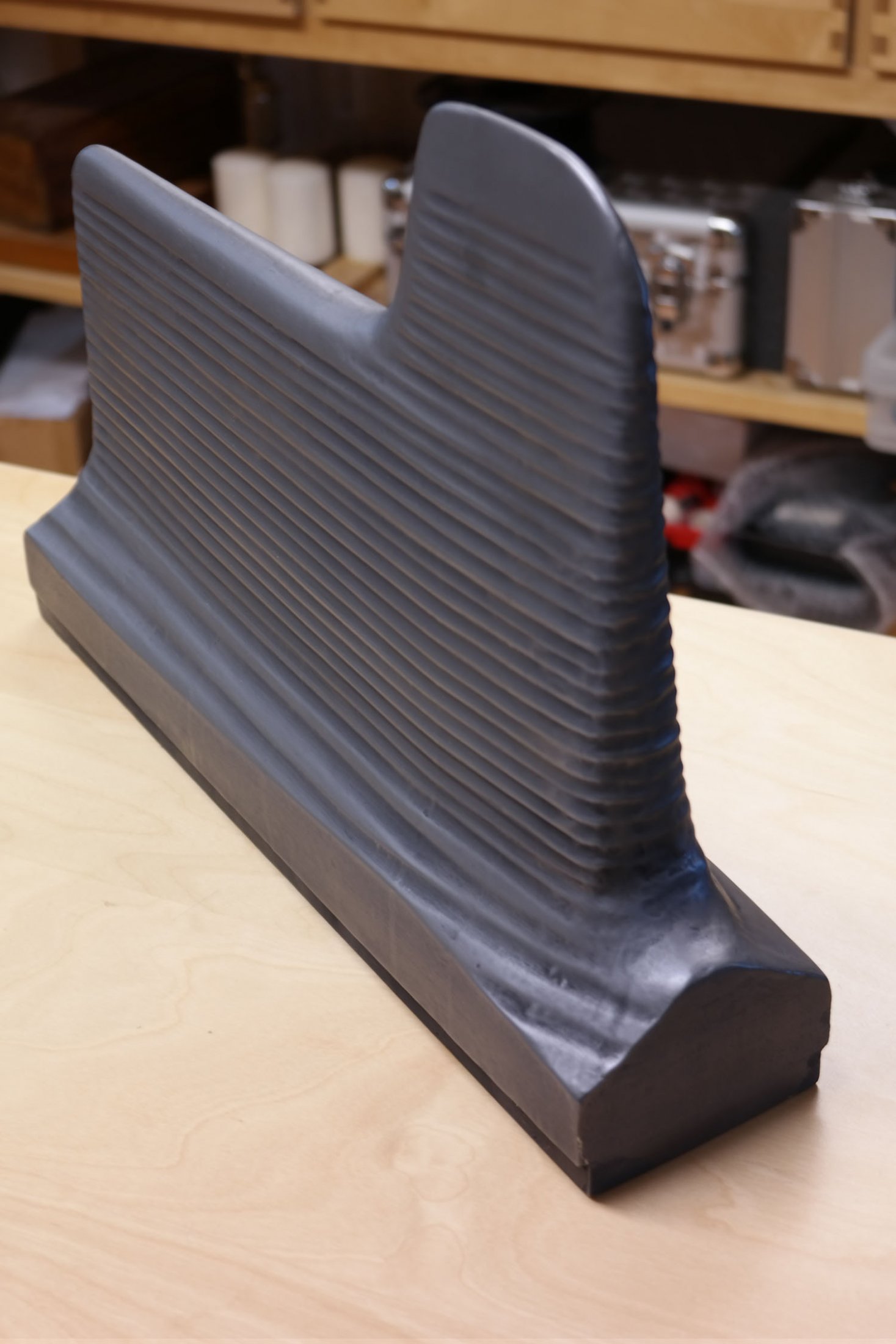
V2 missile graphite jet vane defector replica made for V2 Rocket History. This accurate replica shows the distinctive pantograph mill tool ‘witness’ marks well.
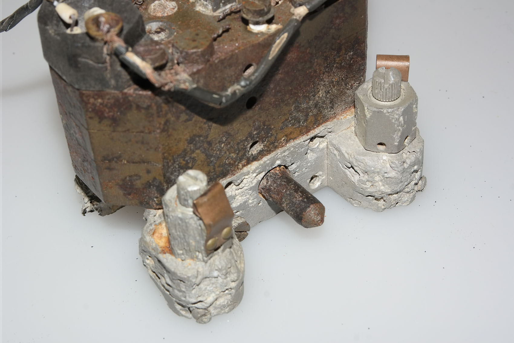
Hydraulic gear pump detail
Hydraulic gear pump detail
Close-up of Askania gear pump relic with oil heaters. This picture shows an unusual feature on the otherwise normal cast aluminium base of this gear pump. The knurled knob positioned between the oil flow balance adjusters has a purpose that is unknown to us. The two oil-flow balance adjuster valves visible in the picture have slot head adjuster screws and you can also see the knurled circumference on each screw. This parallel knurling is engaged by a crease formed in the facing surface of the copper spring strips. The function of these strips is to create tactile feedback that the technician making the adjustment can feel in the handle of the screwdriver. This was done because the gear pump needed to be adjusted in a dark and narrowly confined space.
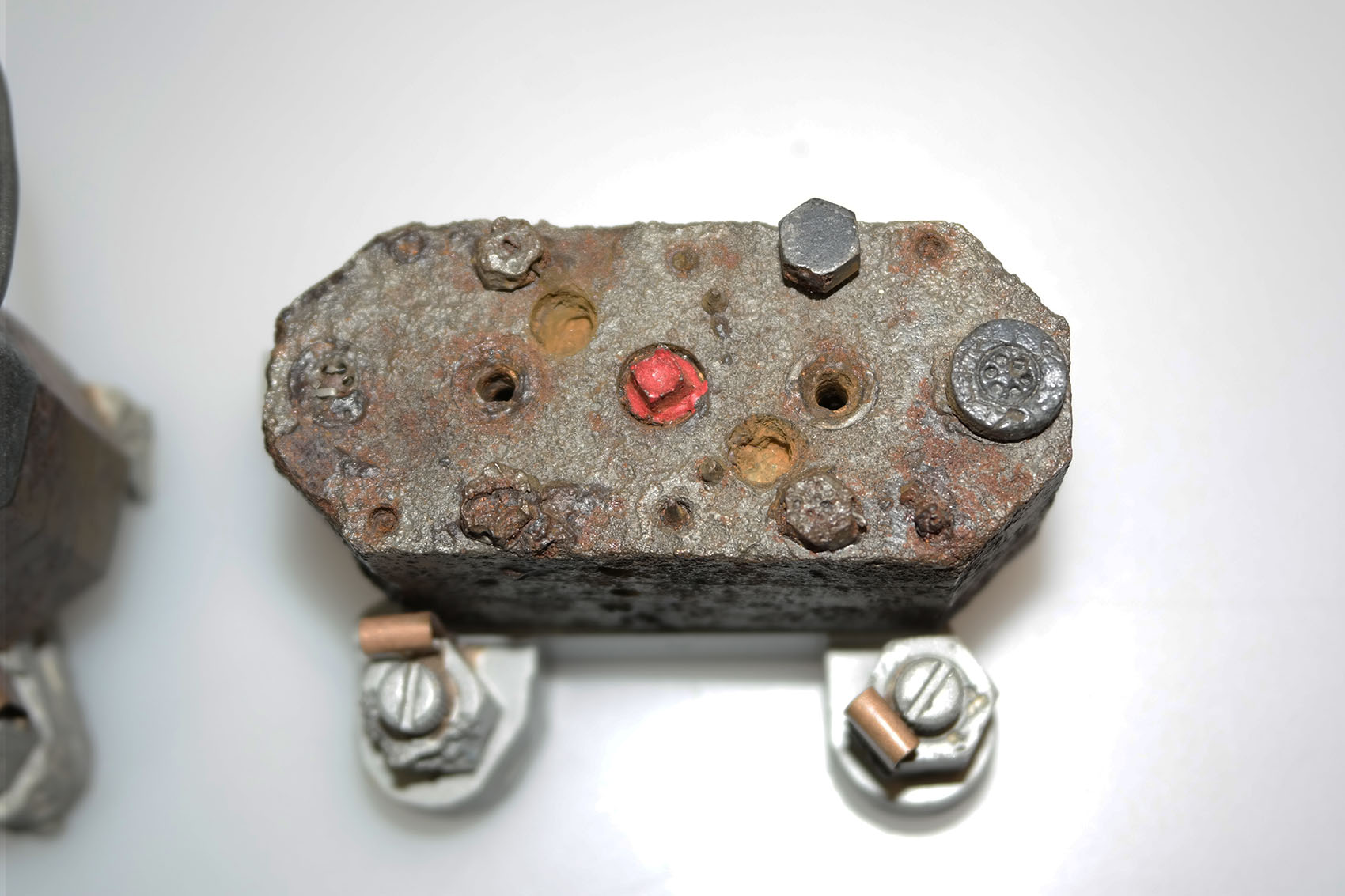
Gear pump showing flow adjusters and ceramic heater elements
Gear pump showing flow adjusters and ceramic heater elements
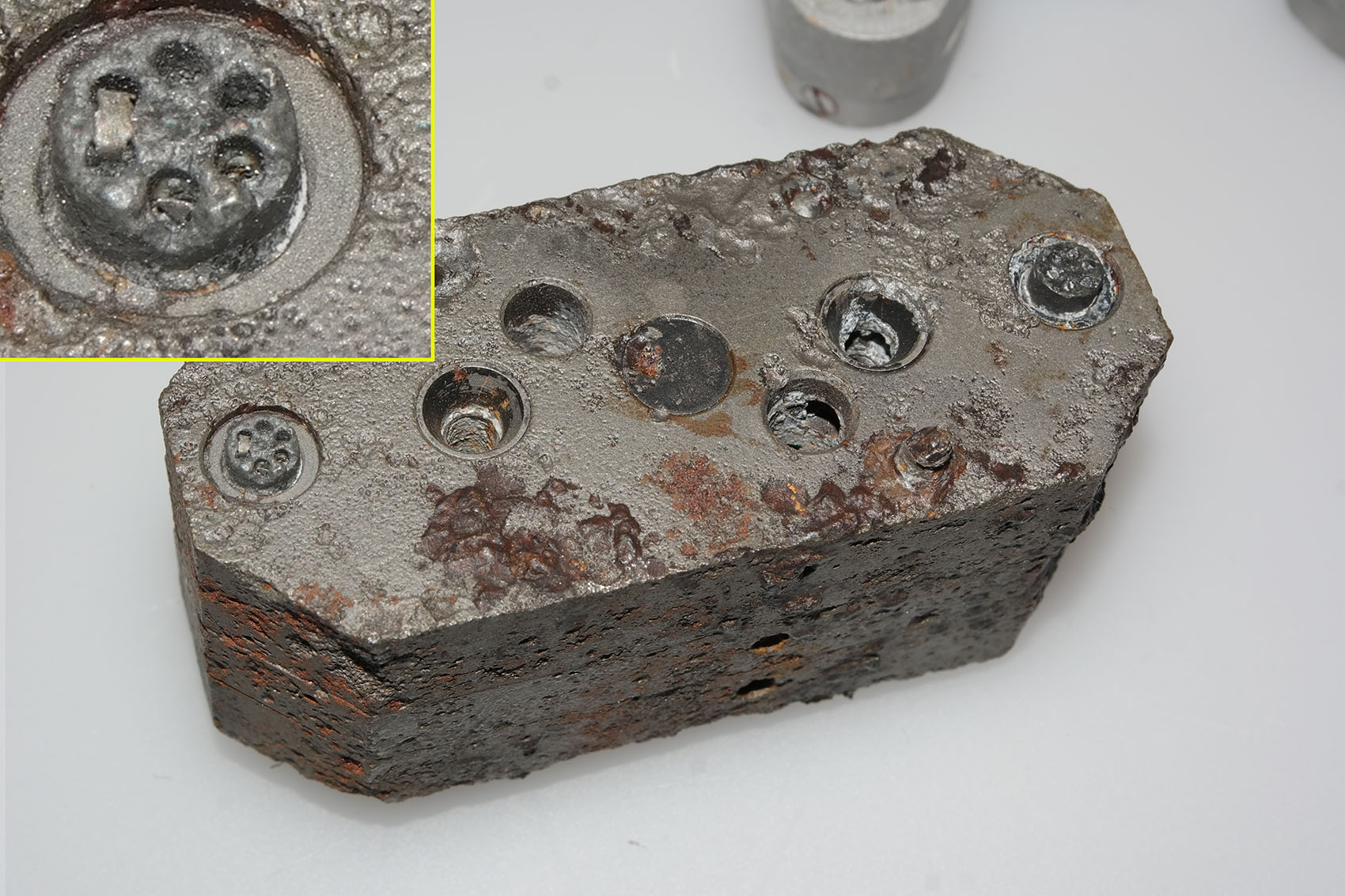
Gear pump showing flow adjusters (two slot head screws nearest bottom of picture) and ceramic heater elements situated at each end of the block. The square drive shaft coupler (corroded but still identifiable) has been highlighted in red paint. The open holes either side are the main control valve guides. The copper spring strips visible on each oil flow adjuster provide locking and tactile feed-back for the adjusting process. This relic was recovered from Usedom island.
F1: Fertigungshalle Eins
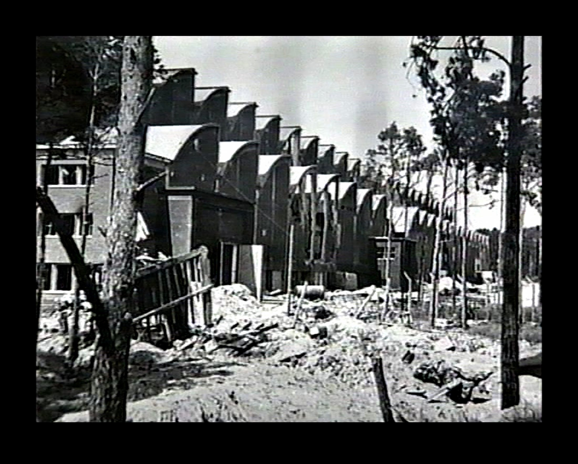
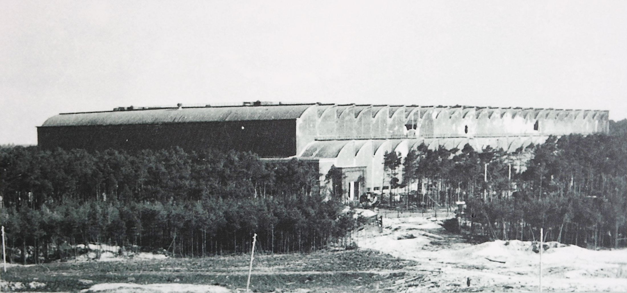
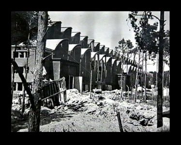
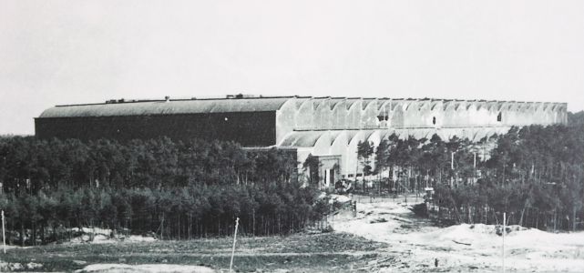
Bomb damaged F1 factory 1945
Bomb damaged F1 factory 1945
Bomb damaged F1 factory 1945. The huge V2 rocket factory shown badly damaged by air attack at the end of the war in May 1945
Equipment bays
Control compartment 3
Control compartment 3
Control compartments 3 showing gyro mounting platform with two gyros and DC motor driven 3 phase AC voltage generator. The alcohol tank pressurisation pipe is also shown running through the equipment bay (large silver coloured pipe). Image copyright Imperial War Museum
| Album | Equipment bays |
| Category | Guidence |
Ernst Steinhoff
Ernst Steinhoff
Ernst Steinhoff, chief of the BSM workshop (Guidance and Control) in the development works Peenemunde.
Gear pump detail showing ceramic insulator with nichrome element
Gear pump detail showing ceramic insulator with nichrome element
Hydraulic gear pump with close up detail showing ceramic heater element insulators with flat, possibly nichome, metal strip element threaded through them. This oil heating system was designed to maintain a specific viscosity of the oil regardless of environmental temperature, to better maintain oil flow rates and thus pump efficiency. The heating system is found only rarely on surviving relics.
Graphite jet vane replica
Graphite jet vane replica
V2 missile graphite jet vane defector replica made for V2 Rocket History.
Graphite vane rocket jet deflector replica
Graphite vane rocket jet deflector replica
V2 missile graphite jet vane defector replica made for V2 Rocket History. This accurate replica shows the distinctive pantograph mill tool ‘witness’ marks well.
Hydraulic gear pump detail
Hydraulic gear pump detail
Close-up of Askania gear pump relic with oil heaters. This picture shows an unusual feature on the otherwise normal cast aluminium base of this gear pump. The knurled knob positioned between the oil flow balance adjusters has a purpose that is unknown to us. The two oil-flow balance adjuster valves visible in the picture have slot head adjuster screws and you can also see the knurled circumference on each screw. This parallel knurling is engaged by a crease formed in the facing surface of the copper spring strips. The function of these strips is to create tactile feedback that the technician making the adjustment can feel in the handle of the screwdriver. This was done because the gear pump needed to be adjusted in a dark and narrowly confined space.
Gear pump showing flow adjusters and ceramic heater elements
Gear pump showing flow adjusters and ceramic heater elements
Gear pump showing flow adjusters (two slot head screws nearest bottom of picture) and ceramic heater elements situated at each end of the block. The square drive shaft coupler (corroded but still identifiable) has been highlighted in red paint. The open holes either side are the main control valve guides. The copper spring strips visible on each oil flow adjuster provide locking and tactile feed-back for the adjusting process. This relic was recovered from Usedom island.
Missile guidance equipment
Images of guidance and missile control equiment


Production plant (Versuchsserienwerk)
Material related to the Fertigungshalle Eins (F1) pre-production plant (later simply, production plant) or support facilities like the IW Repair and Maintenance Hall or woodworking shop.
IW and F1 on 19th August 1943
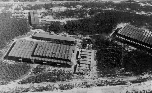

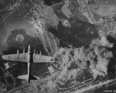
Description
Photo showing Werk Süd with IW on the left and F1 on the right taken on 19th August 1943. The photo shows only light damage to the main halls, although F1 was actually hit at least 11 times, and hits to the separate single storey workshops to the right of the IW hall. The long storage (oil and paint?) shed above IW and the woodworking shop at the top of the picture appear undamaged. Anti-aircraft platforms (at least 3) can be seen on the roof of IW but that seem to be empty of guns. F1 shows two AAA platforms (there was at least 3 at this stage and maybe more) and they may have guns installed. General W. Dornberger mentions defensive AA artillery fire from the from the roof of F1 in his 1952 book V2 (1954 in English).
Location
