

Archives: Gmedia Albums


The Enigmas
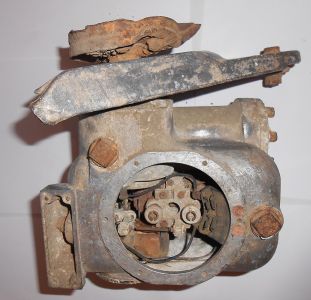
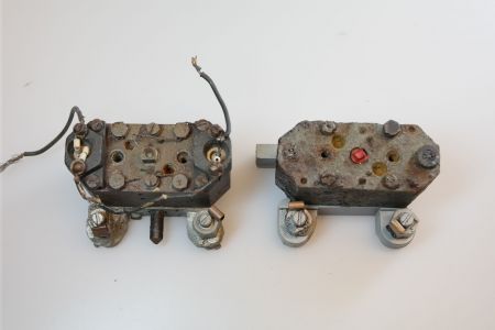
Unknown repair workshop (IW) mechanism
Unknown repair workshop (IW) mechanism
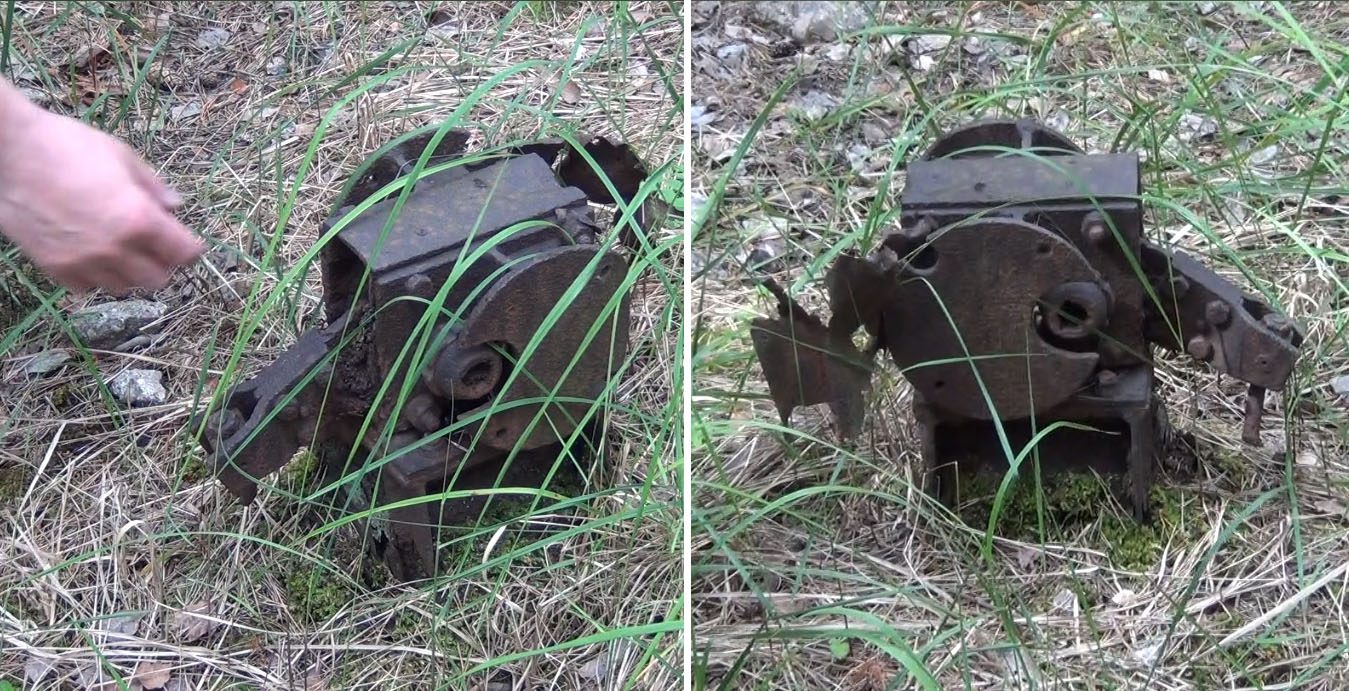
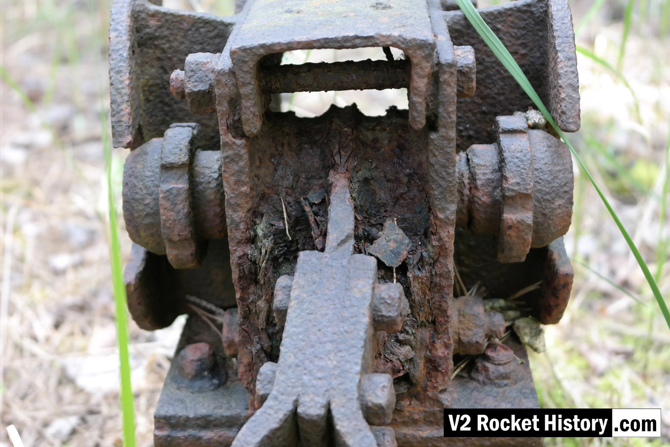
We think this relic, welded to a heavy gauge H beam, may be a points switch for a railway line. But do you know what it is, and what it did? If you do, please tell us.
| Album | The Enigmas |
| Category | Mystery part |
Unknown helical part
Unknown helical part
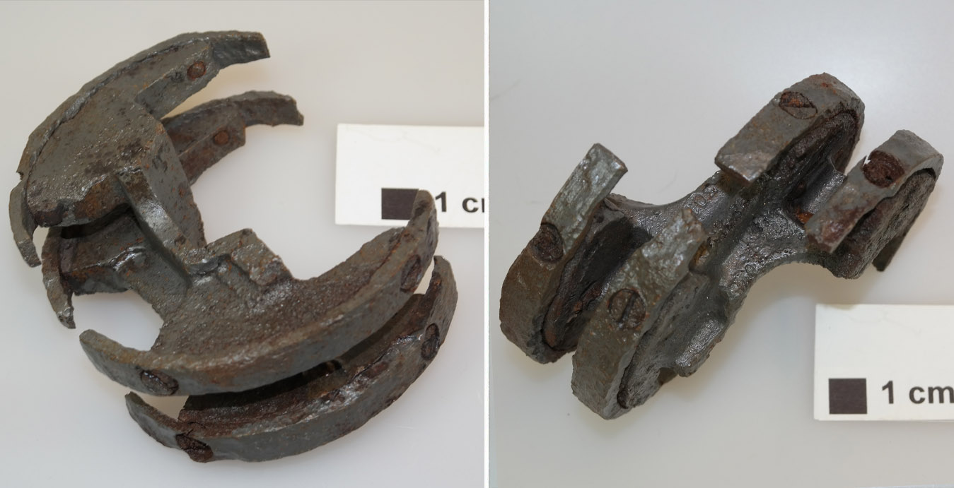
This part has a helicoid or screw shape, it seems that it might have been designed to screw into a pipe of some kind. But do you know what it really is, and what it did? If you do, please tell us.
| Album | The Enigmas |
| Category | Mystery part |
Chain and hook clamp – unknown use
Chain and hook clamp – unknown use
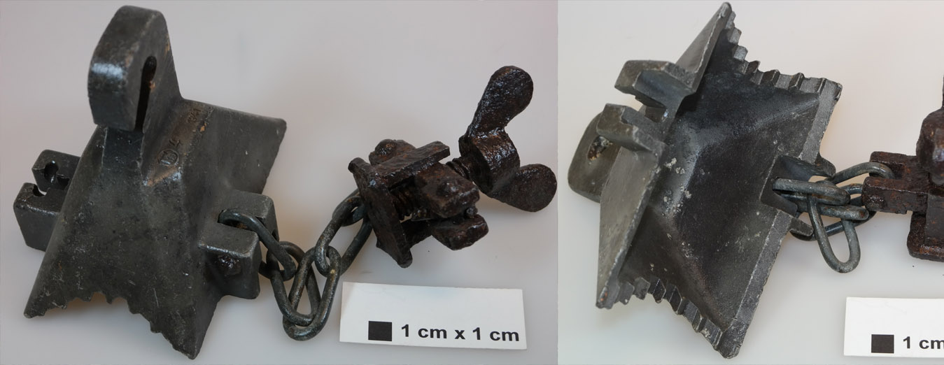
We know this is a clampy-chainy-hooky thing – but do you know what it really is, and what it did? If you do, please tell us.
| Album | The Enigmas |
| Category | Mystery part |
Close up of relic within IW near aisle 20
Close up of relic within IW near aisle 20
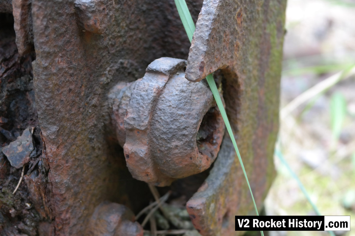
This is a close up of the mystery item, referred to on our Enigma page, found firmly anchored to the floor a few metres inside the east wall near aisle 20 of IW (near location of internal railway line).
| Album | The Enigmas |
| Category | Mystery part |
Close up of relic within IW near aisle 20
Close up of relic within IW near aisle 20
This is another close up of the mystery item showing the mechanism in more detail. It can be found firmly anchored to the floor a few metres inside the east wall near aisle 20 of IW (near location of internal railway line). See map below for location.
| Album | The Enigmas |
| Category | Mystery part |
F1: Fertigungshalle Eins
IW and F1 on 19th August 1943
IW and F1 on 19th August 1943
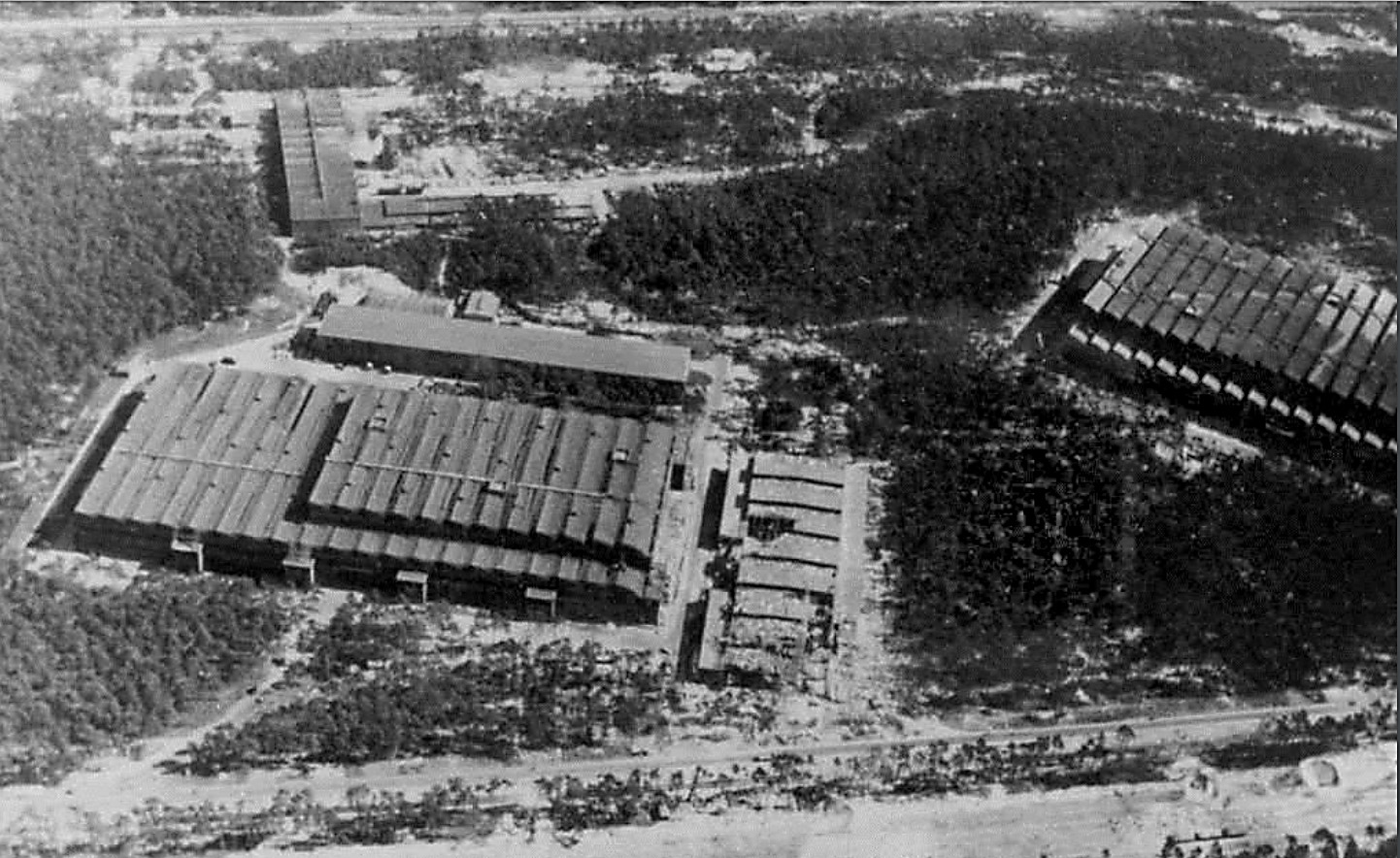
Photo showing Werk Süd with IW on the left and F1 on the right taken on 19th August 1943. The photo shows only light damage to the main halls, although F1 was actually hit at least 11 times, and hits to the separate single storey workshops to the right of the IW hall. The long storage (oil and paint?) shed above IW and the woodworking shop at the top of the picture appear undamaged. Anti-aircraft platforms (at least 3) can be seen on the roof of IW but that seem to be empty of guns. F1 shows two AAA platforms (there was at least 3 at this stage and maybe more) and they may have guns installed. General W. Dornberger mentions defensive AA artillery fire from the from the roof of F1 in his 1952 book V2 (1954 in English).

The IW ‘oil shed’ loading stage
The IW ‘oil shed’ loading stage
The remains of the a rail and truck loading stage located in the long oil storage shed adjacent to the IW repair and maintenance hall (IW R&MH) are substantial and have intact steadying chains along the south edge of the platform. There are access steps to the west and east ends (east shown). This loading stage was originally furnished with a wooden platform.
Bomb damaged F1 factory 1945
Bomb damaged F1 factory 1945
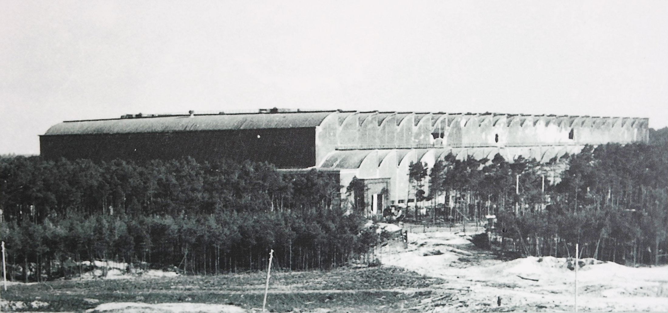
Bomb damaged F1 factory 1945. The huge V2 rocket factory shown badly damaged by air attack at the end of the war in May 1945
Fertigungshalle Eins (F1) after the RAF raid of 1943
Fertigungshalle Eins (F1) after the RAF raid of 1943
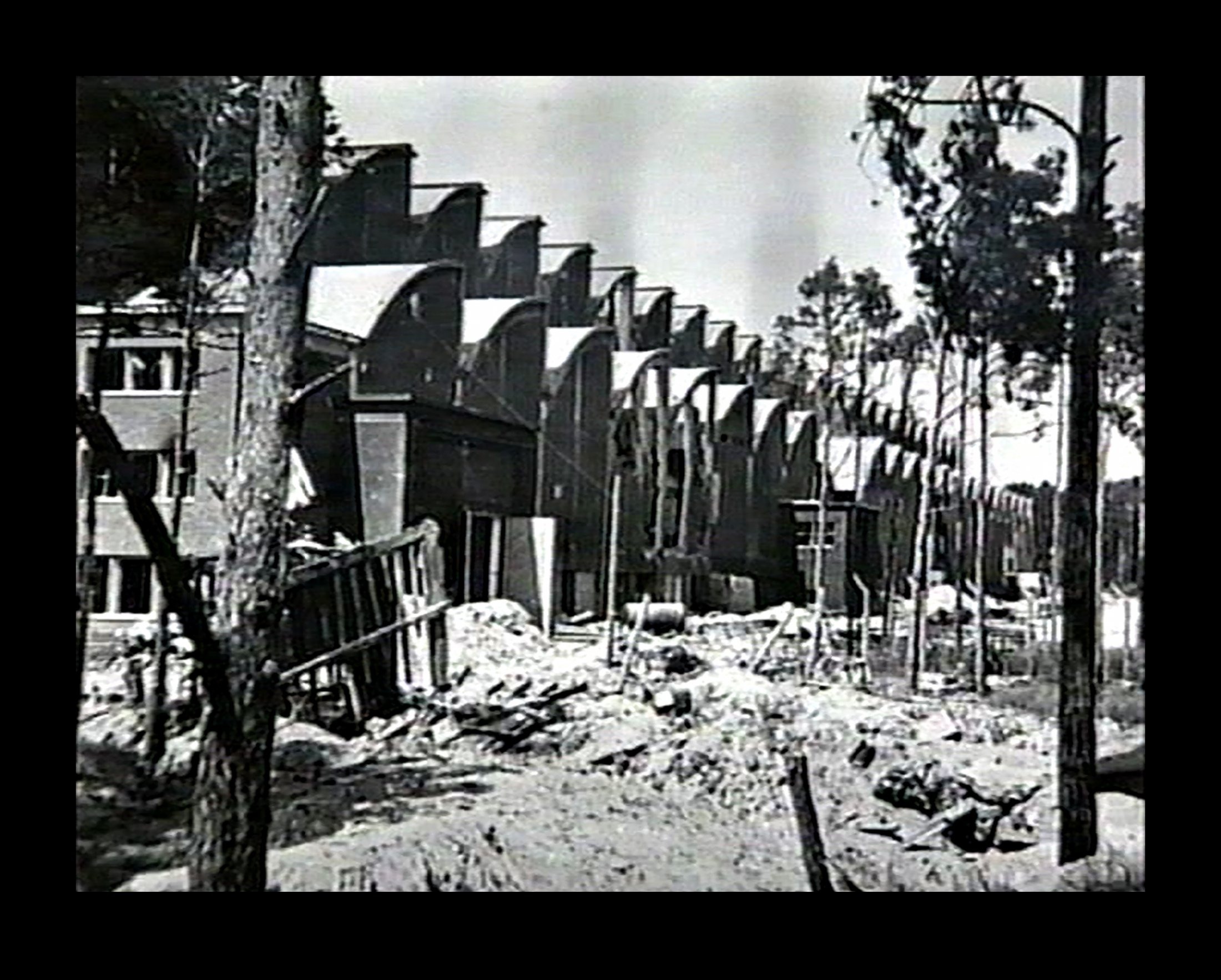
A rare photo of the giant F1 production hall taken not long after the RAF raid of 17/18th August 1943. F1 was a forced labour camp with at least 600 prisoners living within the factory and at least eleven were killed in the raid. Parts of the electrified barbed wire fence can be seen close to the factory building, in the clearing in the middle of the photo. Two anti aircraft gun emplacements can be seen on the roof at the front of the building. Holes in the side walls of the upper vaults can be seen as well as the damage to lower vaults 9 and 10 (counting from left) from a direct hit in this region. Also of note are the numerous guy ropes, attached to the upper roof of the front of the building – and running down towards the trees, that are just visible in the photo. These may be supports for camouflage netting that was in the process of being fitted (by prisoner gangs) just before the raid. The work was never completed.
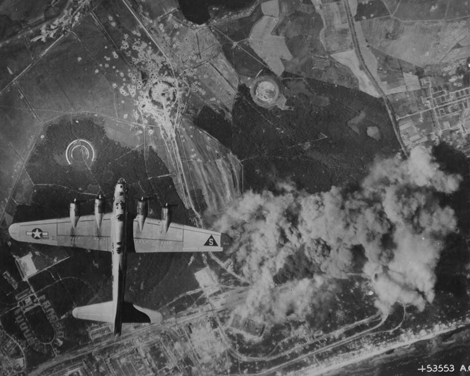
Peenemünde: Werk Sud attacked by US bombers August 1944
Peenemünde: Werk Sud attacked by US bombers August 1944
Peenemünde: Werk Sud attacked by US bombers August 1944 in a daring daylight raid. The two large halls F1 and IW in the lower middle of the photo are under direct attack and smoke can be seen originating from both buildings. Although the August 1944 raids did little to interrupt the volume manufacture of the V2, as virtually all manufacturing and assembly of the missile had moved to central Germany, the raids did bring to an almost complete halt the last small amount of manufacturing work still competed in the giant halls of Werk Sud.
Equipment bays

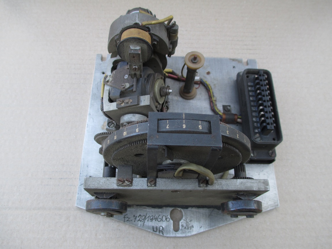
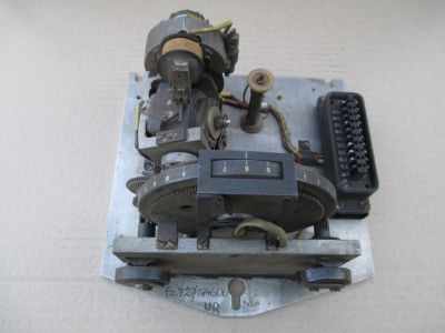
LEV-3 Horizont and Vertikant gyroscope system 1940
LEV-3 Horizont and Vertikant gyroscope system 1940
LEV-3 V2 missile gyroscope system with mounting plate. The third component of this system, the Muller gyroscopic accelerometer, is missing – the 2x mounting points can be seen on the right-hand side of the mounting plate.
| Album | Missile guidance equipment |
| Categories | Missile guidence, Sub-assemblies |
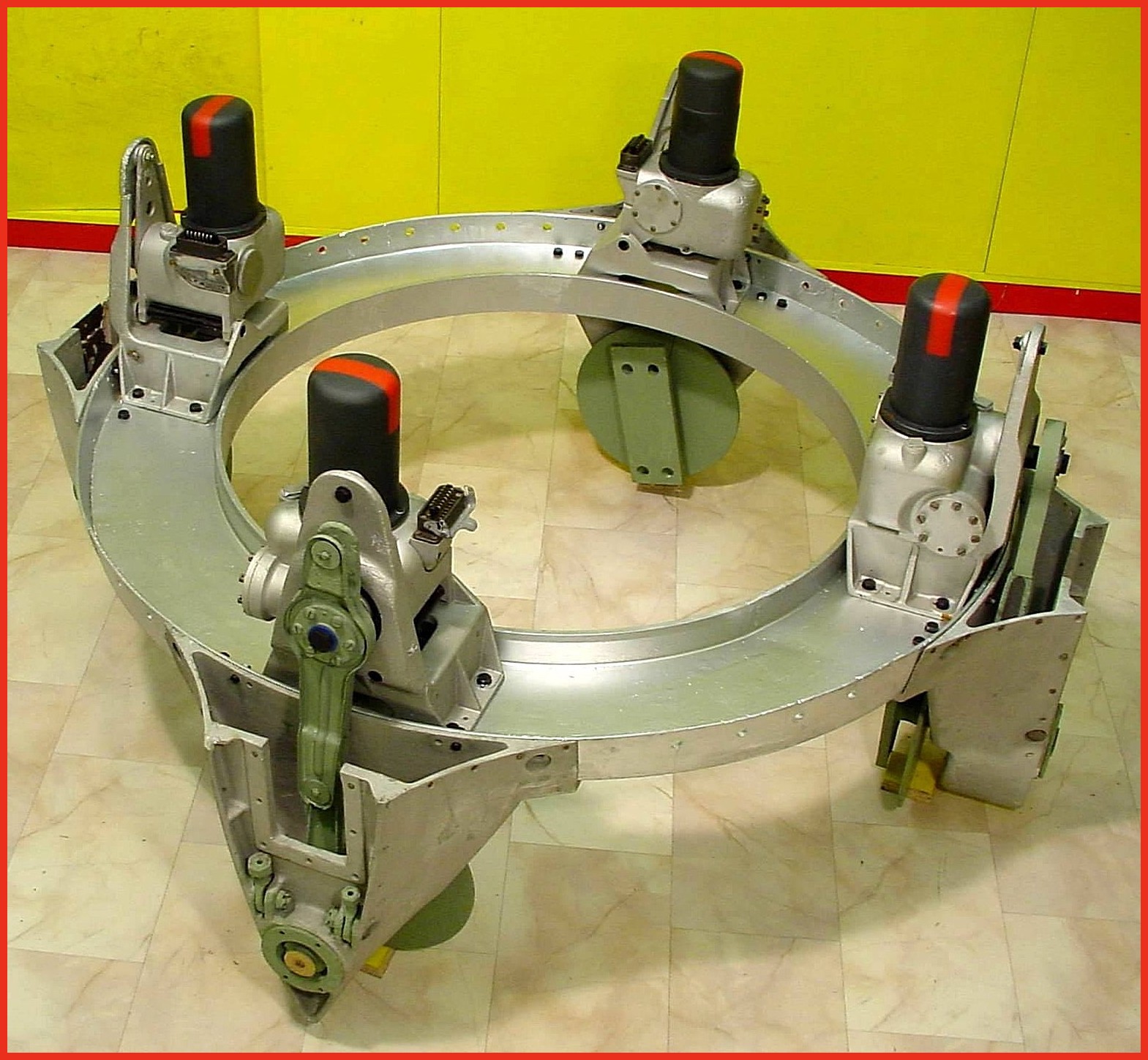
A4-V2 thrust ring with control servos (Abtriebsring) ©THBC
A4-V2 thrust ring with control servos (Abtriebsring) ©THBC
Photo shows cast aluminium thrust ring with electro-hydraulic servos in position. Note different crank lever shapes (pale green arm on servo) for fins 1/3 and 2/4 This excellent restoration is the work of Horst Beck. Photo copyright: The Horst Beck Collection
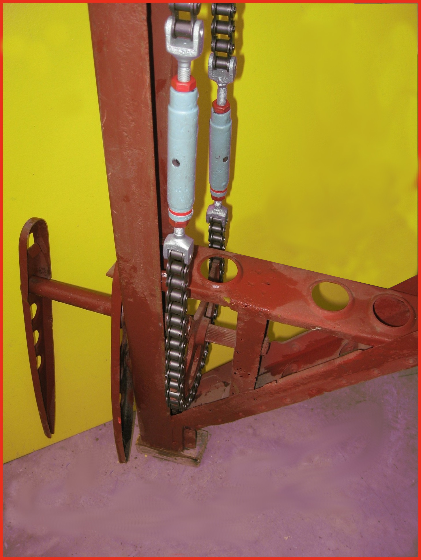
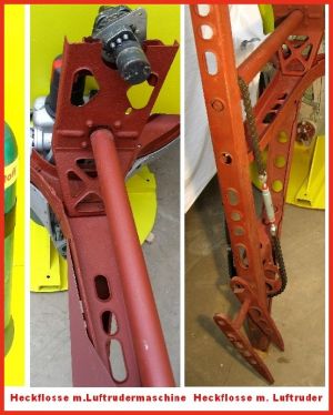
A4-V2 air rudder detail. ©THBC
A4-V2 air rudder detail. ©THBC
Photo shows restored air-rudder and fin detail. The grey painted barrel-strainers are both adjusted independently to reduce slack in the drive chain and avoid introducing a deflection bias in the air rudder. The 1.9kg counterbalance weight normally located at the top of the trim fin (or air rudder) is missing in this presentation. This excellent restoration is the work of Horst Beck. Photo copyright: The Horst Beck Collection

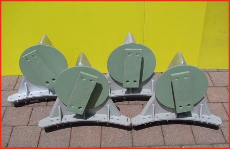
Restored graphite vane thrust ring support housings. ©THBC
Restored graphite vane thrust ring support housings. ©THBC
Photo shows four restored graphite jet vane support blocks and bearing housings. The round plates we can see here act as heat sinks and allow heat to radiate away from the support block and bearing to help prevent expansion due to relatively rapid and uneven temperature distribution accumulation. The graphite vanes were quite brittle and cracking caused by rapid and uneven expansion could cause the vane to disintegrate. The area around the graphite vanes was exposed to the accumulation of heat not merely as a result of duration of the motor burn time but temperature was also increased at higher rates as the jet plume expanded with the decreasing atmospheric pressure as the missile gained altitude. This excellent restoration is the work of Horst Beck. Photo copyright: The Horst Beck Collection
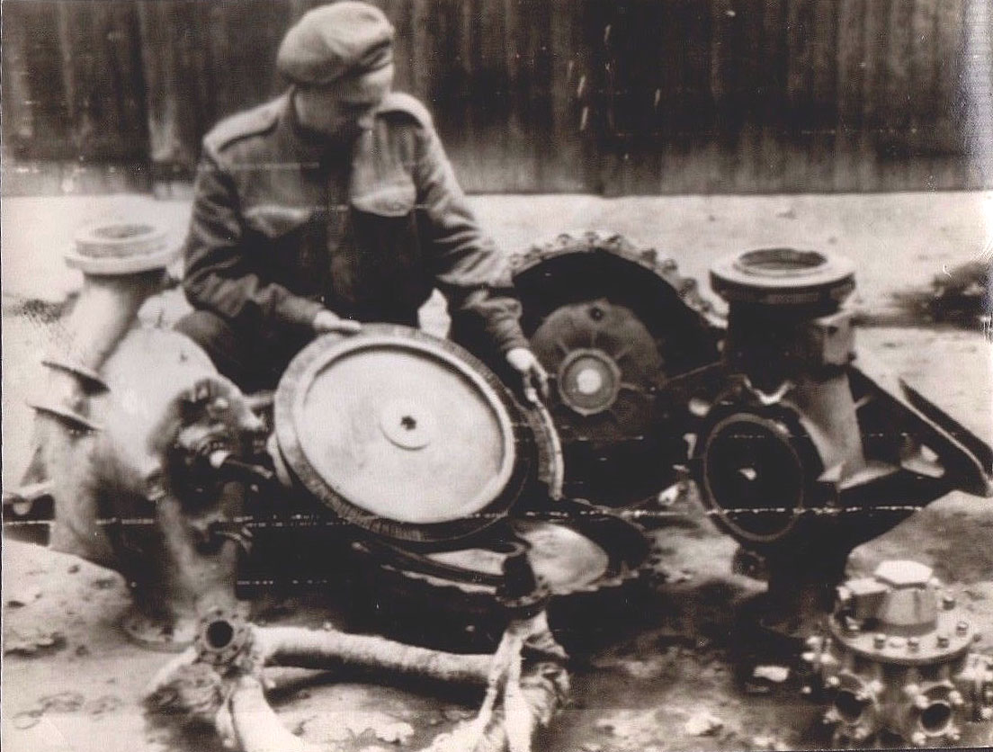
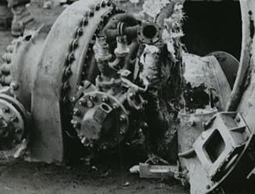
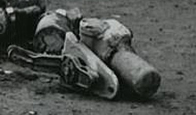
Turbo Pump Parts Showing Steam Rotor
Turbo Pump Parts Showing Steam Rotor
Image shows allied soldier examining remains of V2 rocket turbo-pump after impact. The soldier is holding the steam turbine rotor – the large size of this part is well shown in this photo. The still lagged steam inlet manifold can be seen in the left foreground and the LOX outlet manifold (and valve, topmost) can be seen in the lower right corner.
Smashed TP Antwerp Impact
Smashed TP Antwerp Impact
Picture shows tubo-pump debris from impact site. LOX manifold clearly seen (3 in 1 outlet pipes, upper center of image – the one to its right, 2 o’clock position, and left, 11 o’clock position are both broken off).The LOX flow electric control valve is also well displayed in this image (LOX valve head is slightly low and left of center, part nearest camera). The electrical connection to the LOX valve has broken away leaving its empty socket pointing upwards and to the right.
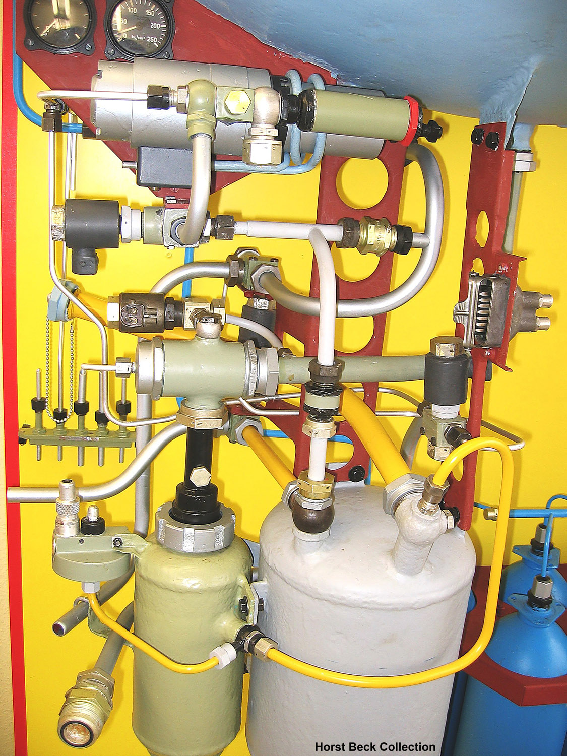
A4-V2 missile steam generator detail
A4-V2 missile steam generator detail
A4 missile steam generator detail. This excellent presentation was rebuilt from original refurbished parts by Horst Beck. See our video article The V2 Rocket Turbo-Pump for a technical exposition of the parts shown in this photo. Image courtesy The Horst Beck Collection
Klein Schanzlin & Becker centrifug-pump advert
Klein Schanzlin & Becker centrifug-pump advert
Klein Schanzlin & Becker electric centrifugal-pump advert.
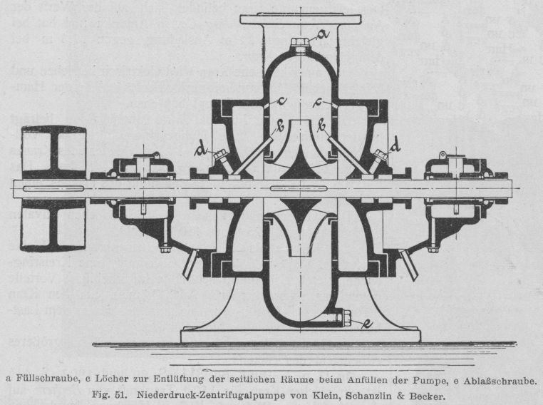
Early belt powered centrifugal pump by KSB with V2 TP features
Early belt powered centrifugal pump by KSB with V2 TP features
Early belt powered centrifugal pump by Klein Schanzlin & Becker. This schematic shows an early 20th century centrifugal pump designed and manufactured by KSB. The drawing appears to show auto-purge pathways at points marked C as well continuous lubrication pathways at B. Both of these important ideas would later feature in the propellant pump of the A4-V2 missile.
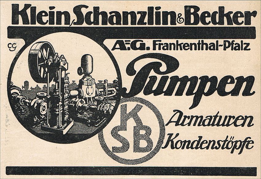
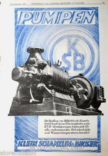
1930s Trade advert for Klein Schanzlin & Becker
1930s Trade advert for Klein Schanzlin & Becker
Trade advertisement for Klein Schanzlin & Becker (KSB supplier code ebb). KSB were the primary contractor for A4-V2 missile’s steam turbine driven dual propellant pump system.
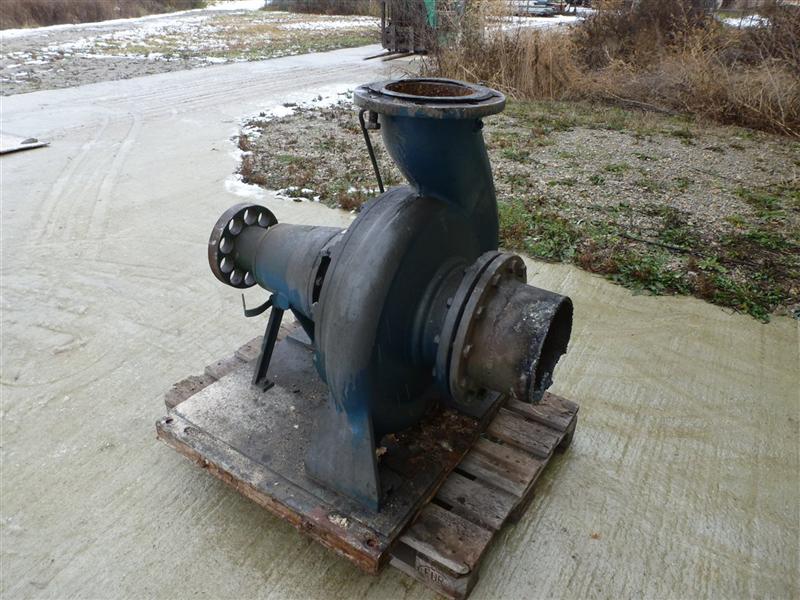
Family photo? Industrial volute case centrifugal pump by KSB
Family photo? Industrial volute case centrifugal pump by KSB
Large industrial volute case centrifugal pump by Klein Schanzlin & Becker. This image highlights the ‘genetic’similarity and family resemblance between KSB’s current and historical product range and the visible features of the A4-V2 missile Turbo-Pump (TP). Apart from the general shape of the cast spiral-volute case and its connection flanges, the ‘soft’ shaft connection (disk with holes on the extreme left of the pump) is very reminiscent of the semi-flexible shaft connection point linking one side the steam turbine rotor shaft to the shaft carrying a propellent pump rotor seen in the A4-V2 missile TP. Family photo? Industrial volute case centrifugal pump by KSB
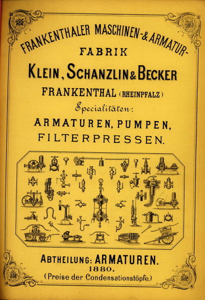
KSB catalogue from 1880
KSB catalogue from 1880
Cover of catalogue published in 1880 showing the KSB product range
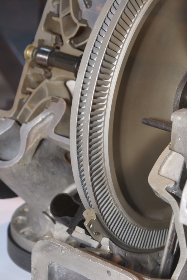
Dual blade V2 turbo-pump steam turbine rotor
Dual blade V2 turbo-pump steam turbine rotor
This image shows a cutaway of an A4-V2 turbo-pump. The section reveals the Curtis type 2-stage steam-turbine rotor and you can also see part of the stater inserted between the blades (bottom middle) and the adjacent steam distribution pipe (black open pipe on stater’s immediate left). Top left, a centrifugal pump rotor can be seen – cut through, it shows a multi-splined shaft running through the centre, simple bearing and end-cap.
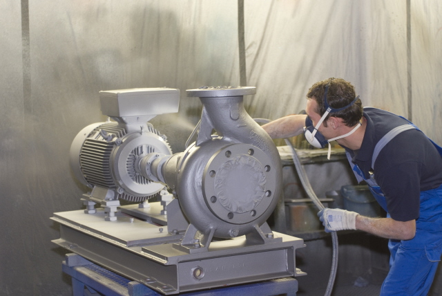
Family photo? Electric volute case centrifugal pump by KSB
Family photo? Electric volute case centrifugal pump by KSB
Electric industrial volute case centrifugal pump by Klein Schanzlin & Becker. This image highlights the ‘genetic’similarity and family resemblance between KSB’s current and historical product range and the visible features of the A4-V2 missile Turbo-Pump (TP). Assembly is shown being spray painted.
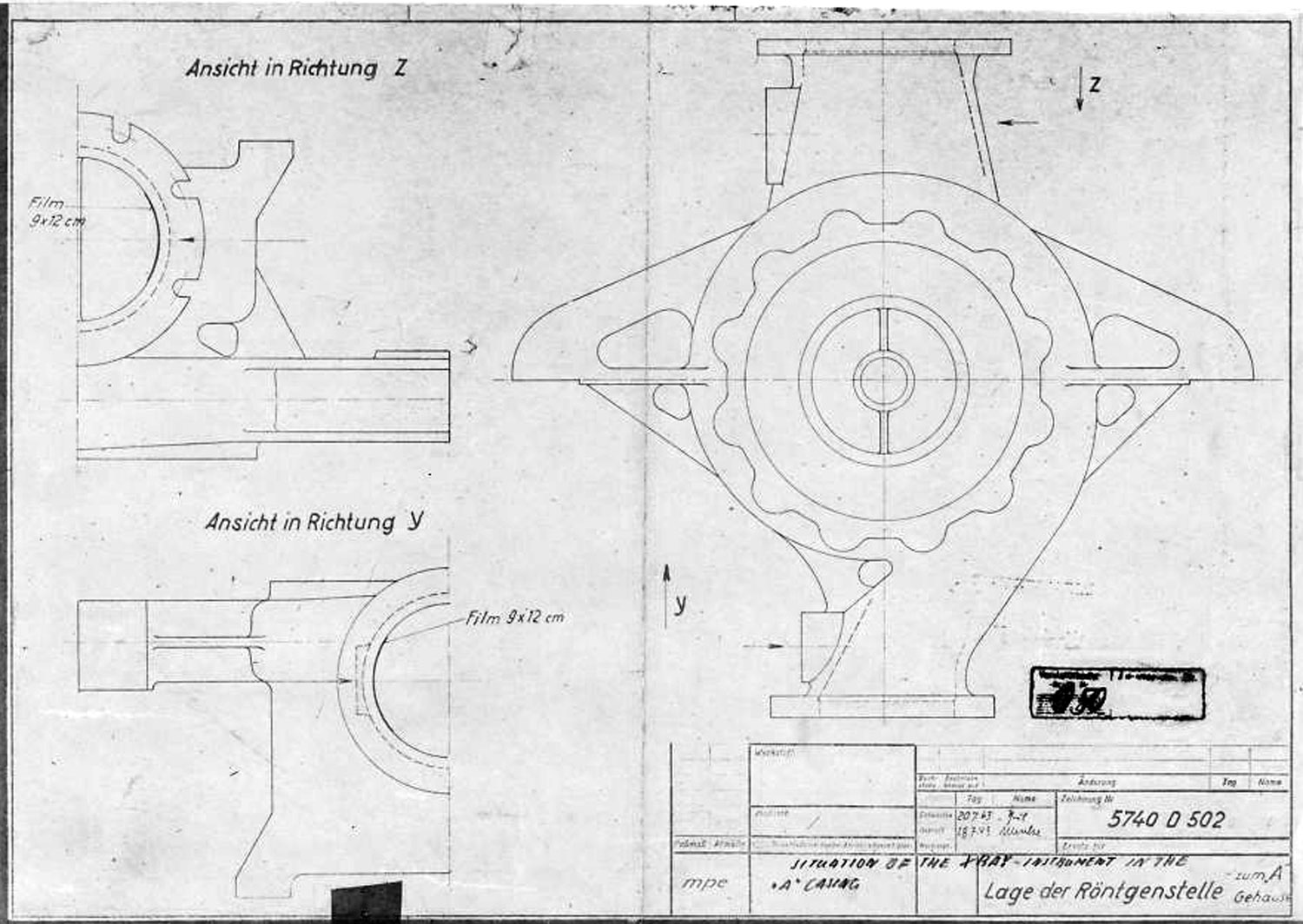
V2 rocket A Stoff (LOX) pump casing 5740
V2 rocket A Stoff (LOX) pump casing 5740
A Stoff (liquid oxygen) pump casing diagram showing stress points that require X ray quality control photography before use. The diagram shows the specific locations where photographic film is to be placed for X-ray analysis.
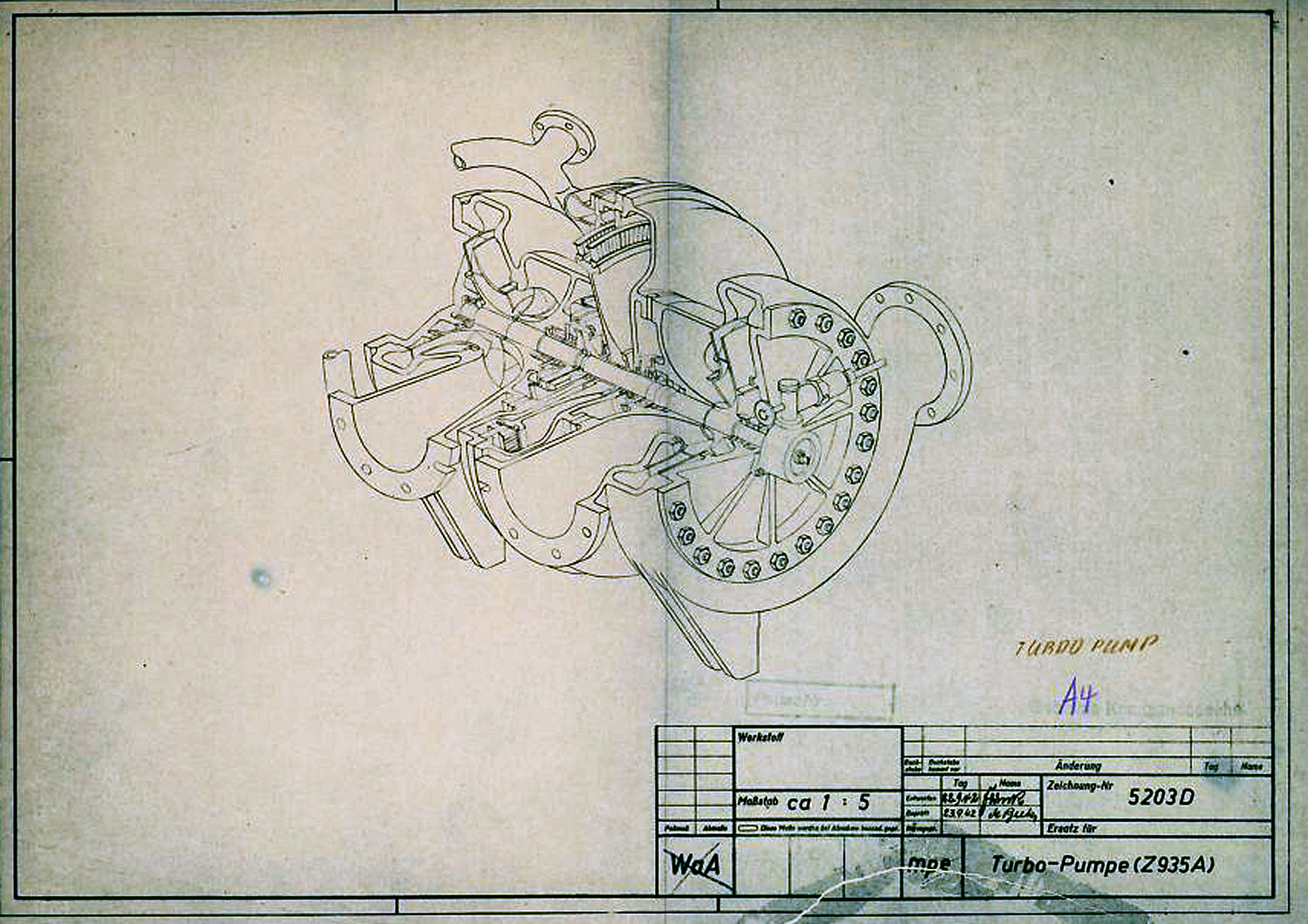
Turbo-Pump (Z 935 A) cutaway presentation Sept 1942
Turbo-Pump (Z 935 A) cutaway presentation Sept 1942
In this diagram the V2 Turbo-pump is shown in a cutaway presentation and rotated 90 degrees counter clockwise. The B stoff (fuel) pump is nearest the viewer – the over-speed device can be seen on the B stoff pump’s case end-plate. The low pressure inlet ports our shown to the left, and high-pressure outlet ports are on the right. The steam distribution manifold can be seen at the furthest point from the viewer – the steam inlet pipe flange can also be seen. The feed pipe from the steam generator attaches to thus flange.
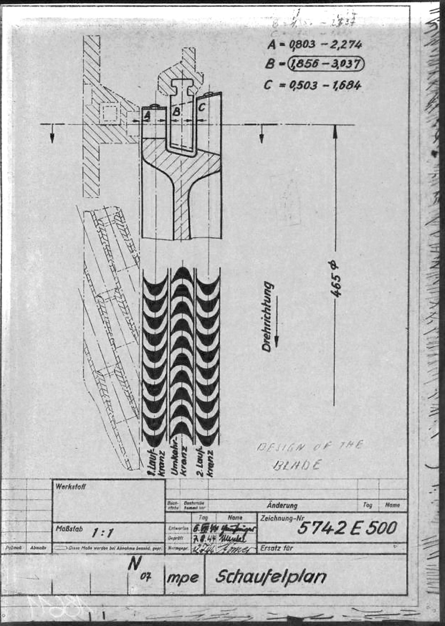
A4-V2 Steam rotor blade design and position 5742 B 1944
A4-V2 Steam rotor blade design and position 5742 B 1944
This mpe* drawing from 1945 shows the individual steam buckets or blades (labeled A and C) mounted to the rim of the rotor disk. As well as the fixed (i.e. stationary) stater blade B, positioned such that blades A & C can pass either side of it. The steam expansion is well shown by the increasing surface area of the blades from A to C, and growing larger, from left where the high pressure super heated steam enters the turbine, to right where it exits the blade pathway and passes in to the exhaust outlet. The lower graphic shows the way the super-heated high pressure steam is passed from the initial A blade and deflected by the reversed B stator blade for its energy to to be harvested for a second time by the C rotor blade. * mpe is the secret three letter armament code for Karlshagen, Werk Nord (North Works).
Oddesse Turbo-Pumpe 1940 Br 75 / 20
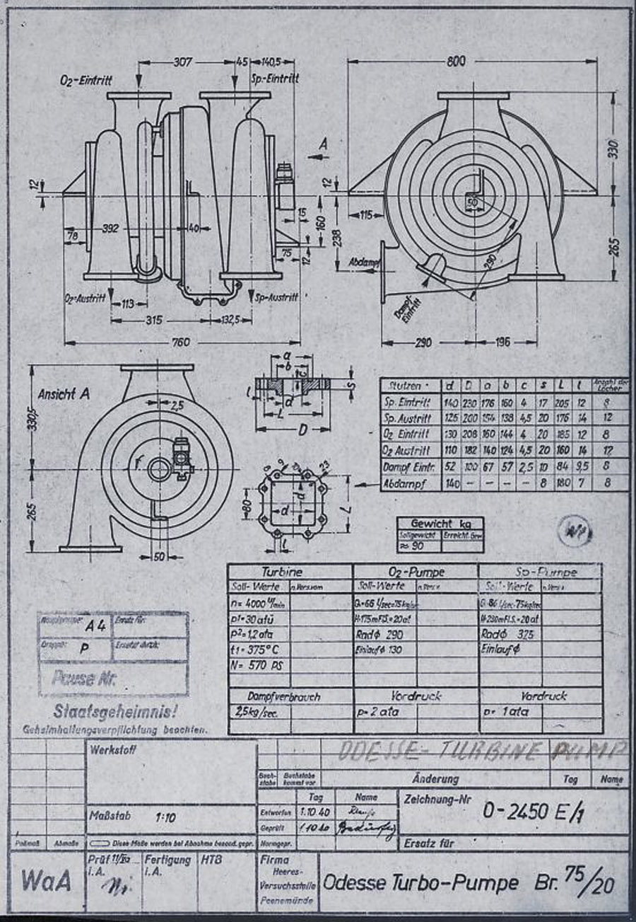
Oddesse Turbo-Pumpe 1940 Br 75 / 20
This HVP technical drawing from October 1940, shows a proposal from the Oddesse company – the full title of this company is KLEIN SCHANZLIN ODDESSE GmbH. Klein, Schanzlin & Becker A.G. (waffenamt code: ebb) took over Oddessa in 1929 and the company became formally known as KLEIN SCHANZLIN-ODDESSE GmbH (code ebc) in 1939. (NB: The company name has nothing to do with a similar sounding place name Odessa. The Oddesse trading name was formed from the partnership of English engineer Oddie, and German businessman Hesse.). The dual centrifugal turbo-pump shown in the drawing is a variant of a high pressure fire-fighting pump manufactured by Oddesse. Note the off-center outflow ports – not also that the outlet flanges are still level at this stage. Note also the incorrect spelling of the company name in the details panel lower right. (Digipeer.de image)
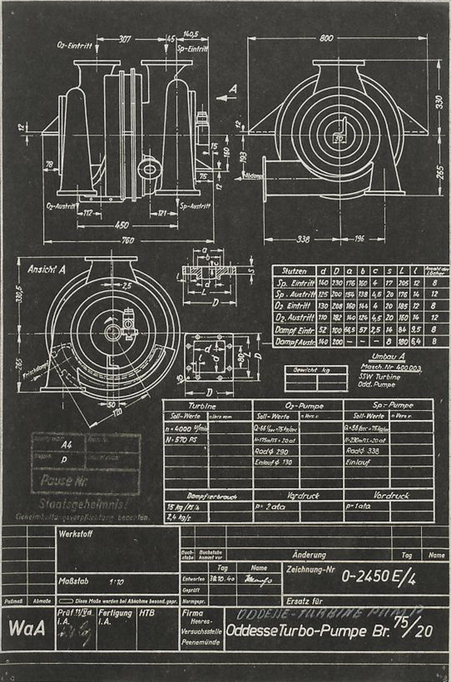
Oddesse Turbo-Pump Br 75 / 20
Oddesse Turbo-Pump Br 75 / 20
Another HVP technical drawing from later in October 1940, shows further data from the KLEIN SCHANZLIN ODDESSE (ebc) company A4-V2 turbo-pump project. See previous image for company details. The dual centrifugal turbo-pump shown in the drawing is a variant of a high pressure fire-fighting pump manufactured by Oddesse. Note the off-center outlet ports. Note also the corrected spelling of the company name in the details panel lower right (see previous Oddesse image) and the small note below the top table that indicates that the pumps are from Oddesse (ODD) and the turbine from a company indicated as SSW. (Digipeer.de image)
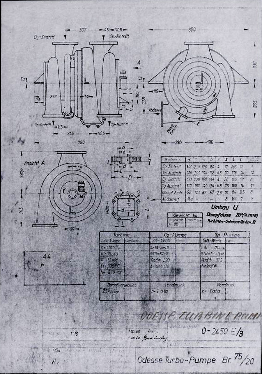
Klein Schanzlin Oddesse Turbo-Pump schema 1940
Klein Schanzlin Oddesse Turbo-Pump schema 1940
Signatur FA 014/21241 (Digipeer.de image)
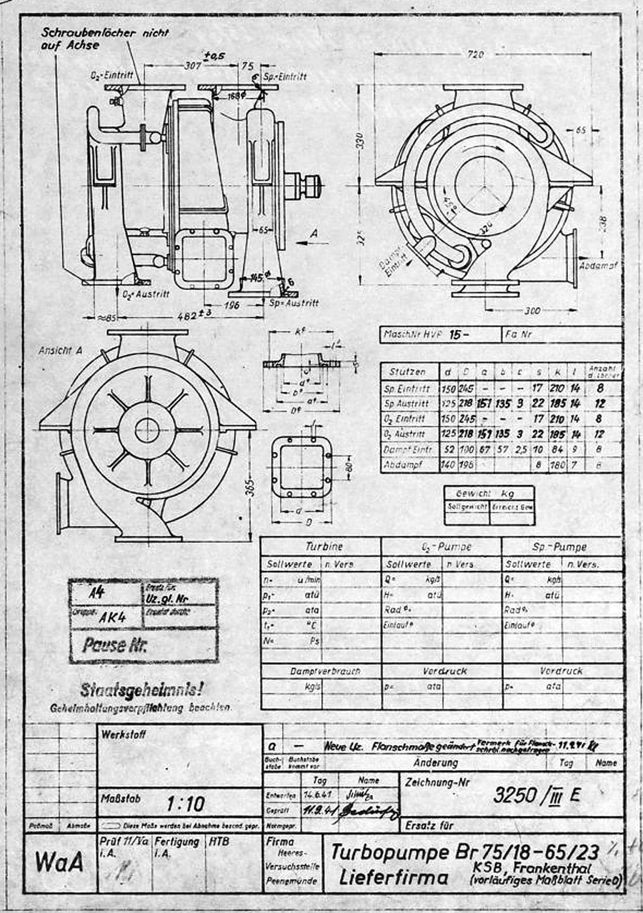
Turbopump Lieferfirma KSB, Frankenthal (vorläufiges Maßblatt Serie 0)
Turbopump Lieferfirma KSB, Frankenthal (vorläufiges Maßblatt Serie 0)
V2 rocket turbo-pump preliminary dimension sheet for O series, drawing. Many of the final elements of the turbo-pump design can be seen in this ‘preliminary’ drawing and table form 1941. The word lieferfirma in the data box btm right mean supply company – and this is indicated to be KSB or Klein Schanzlin & Becker AG, Frankenthal. Signatur FA 014/14769
(Digipeer.de image)
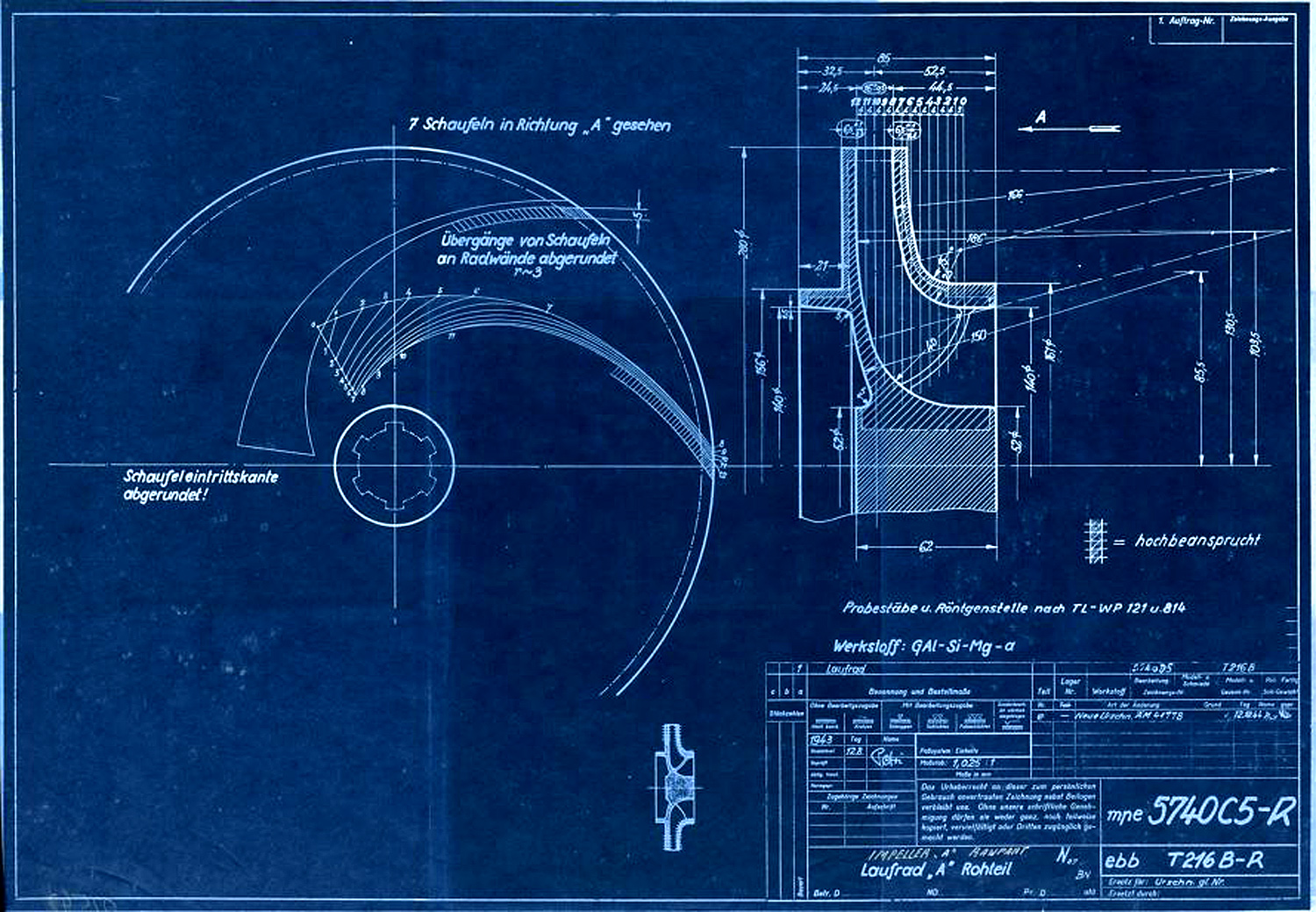
Laufrad A (Rohteil) zur A-Pumpe nach Zeichnungsnummer 5740 B Ausführung A und B [lt. Titelerfassung …
Laufrad A (Rohteil) zur A-Pumpe nach Zeichnungsnummer 5740 B Ausführung A und B [lt. Titelerfassung …
Centrifugal impeller for A or liquid oxygen (LOX) pump. The drawing originated in Aug 1943 and was superseded in December 1944. A key to the image hatching can be seen with the label ‘Hochbeansprucht’ which in English means Highly Stressed. Next to the drawing numbers two secret three letter armament codes can be seen indicating the ‘origination’ of the document. The top one mpe = Heimat Artillerie Park 11 (HAP or Army Artillery Range). The lower code ebb = Klein Schanzlin & Becker AG, Frankenthal.
Signatur FA 014/02542 (Digipeer.de image)
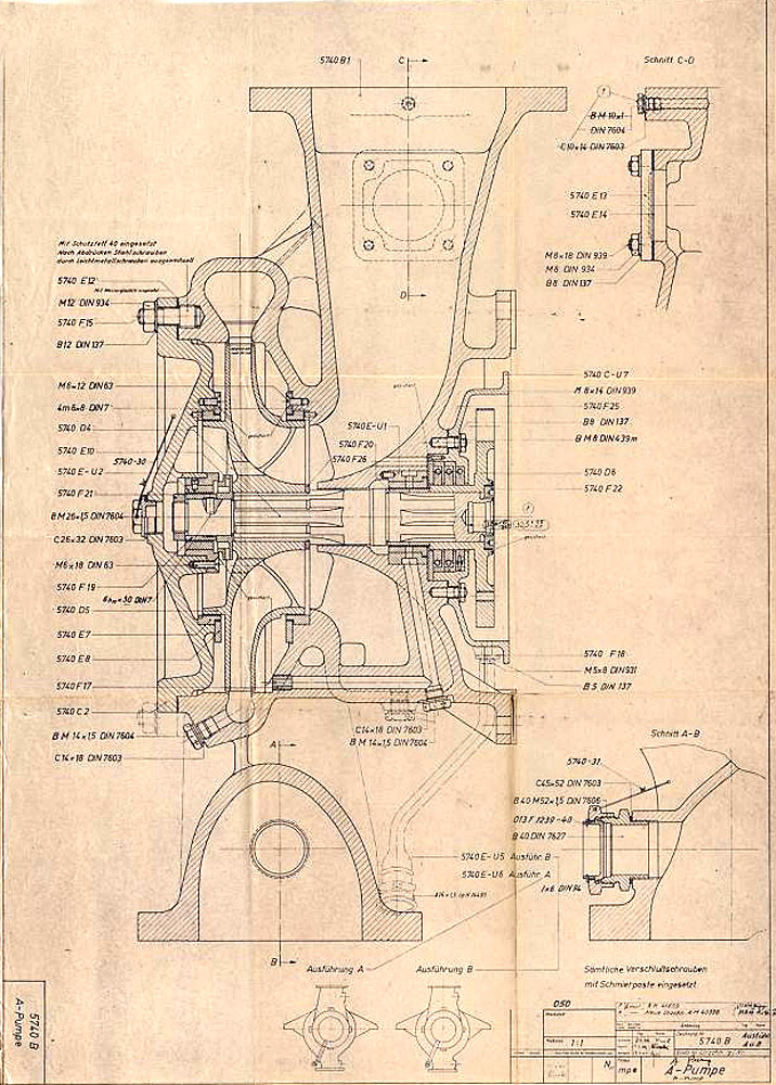
Gehäusedeckel A zur A-Pumpe nach Zeichnungsnummer 5740 B Ausführung A und B
Gehäusedeckel A zur A-Pumpe nach Zeichnungsnummer 5740 B Ausführung A und B
Signatur FA 014/02537
Abmessungen: 42,9×59,8
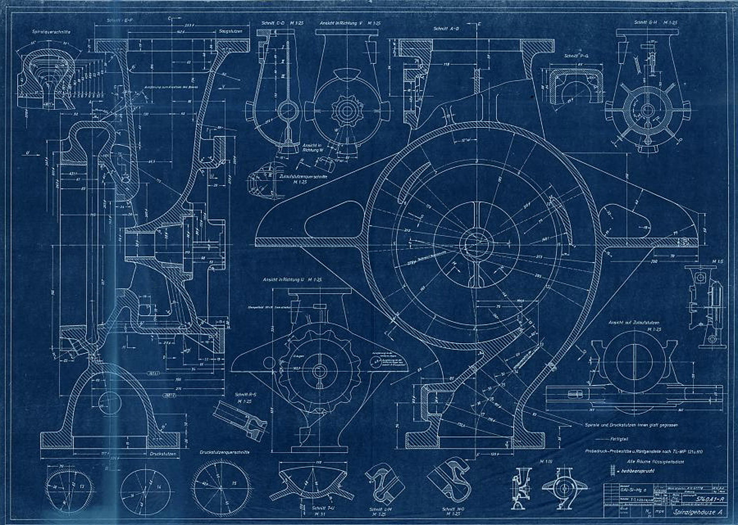
A-Pumpe zur Turbopumpe nach Zeichnungsnummer 5800 A Blatt 1 und 2 (Montagezeichnung)
A-Pumpe zur Turbopumpe nach Zeichnungsnummer 5800 A Blatt 1 und 2 (Montagezeichnung)
Signatur FA 014/02534
Abmessungen: 60,5×82,9
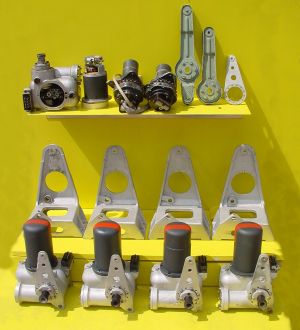
Missile guidance equipment
Images of guidance and missile control equiment


Description
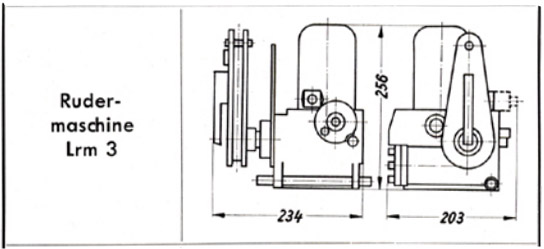
A schematic drawing of the Askania rudder servo ‘Rudermaschine LRM 3’showing the critical compact dimentions of the device making it ideal for retro fit projects for smaller aircraft.
Location
