

Archives: Gmedia Albums


The Enigmas
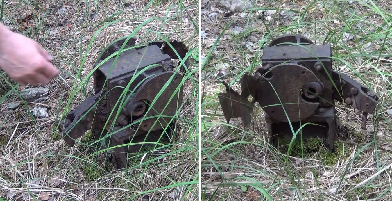
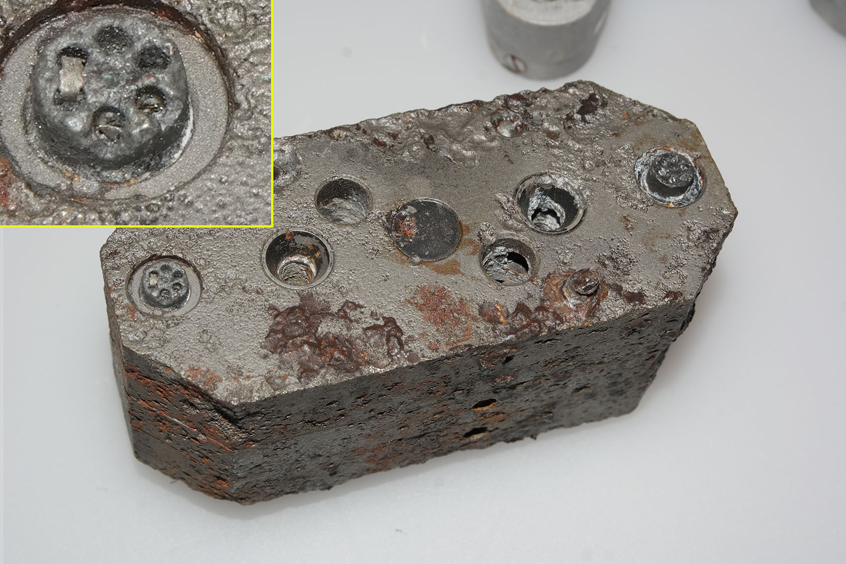
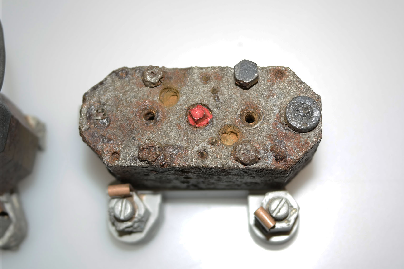
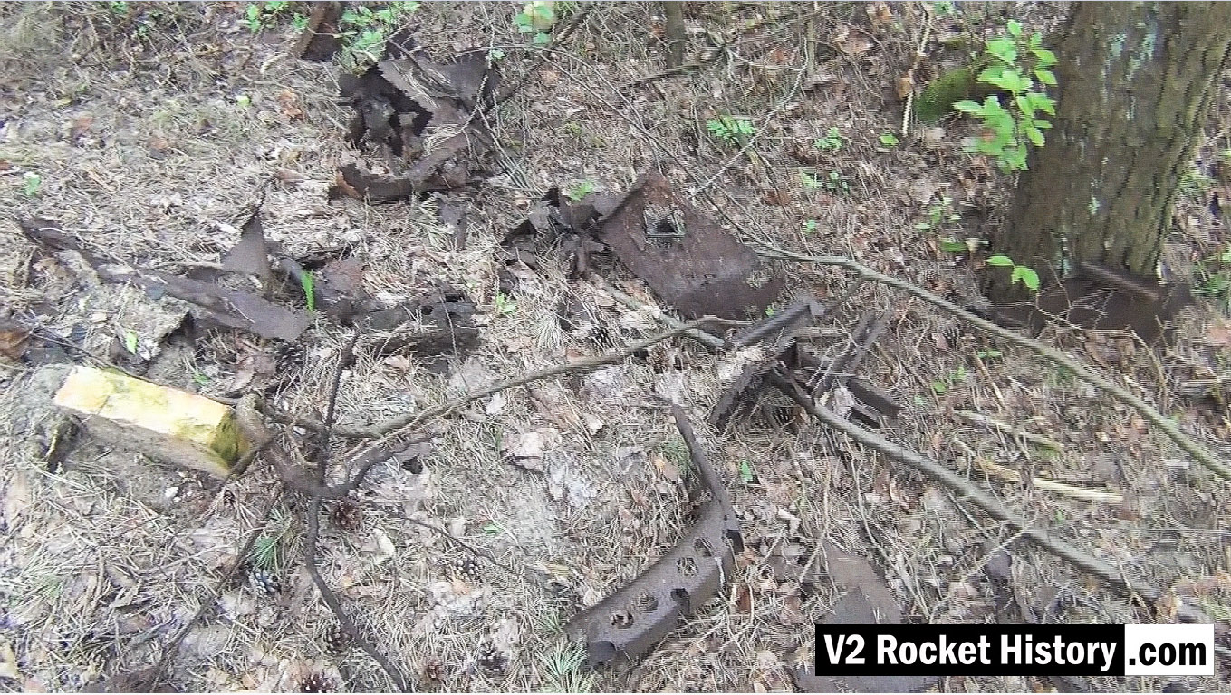
Unknown repair workshop (IW) mechanism
Unknown repair workshop (IW) mechanism
We think this relic, welded to a heavy gauge H beam, may be a points switch for a railway line. But do you know what it is, and what it did? If you do, please tell us.
| Album | The Enigmas |
| Category | Mystery part |
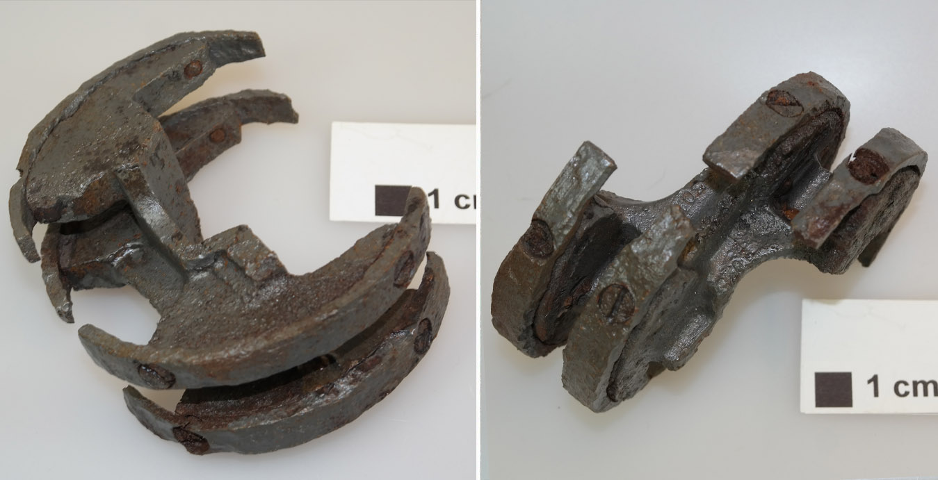
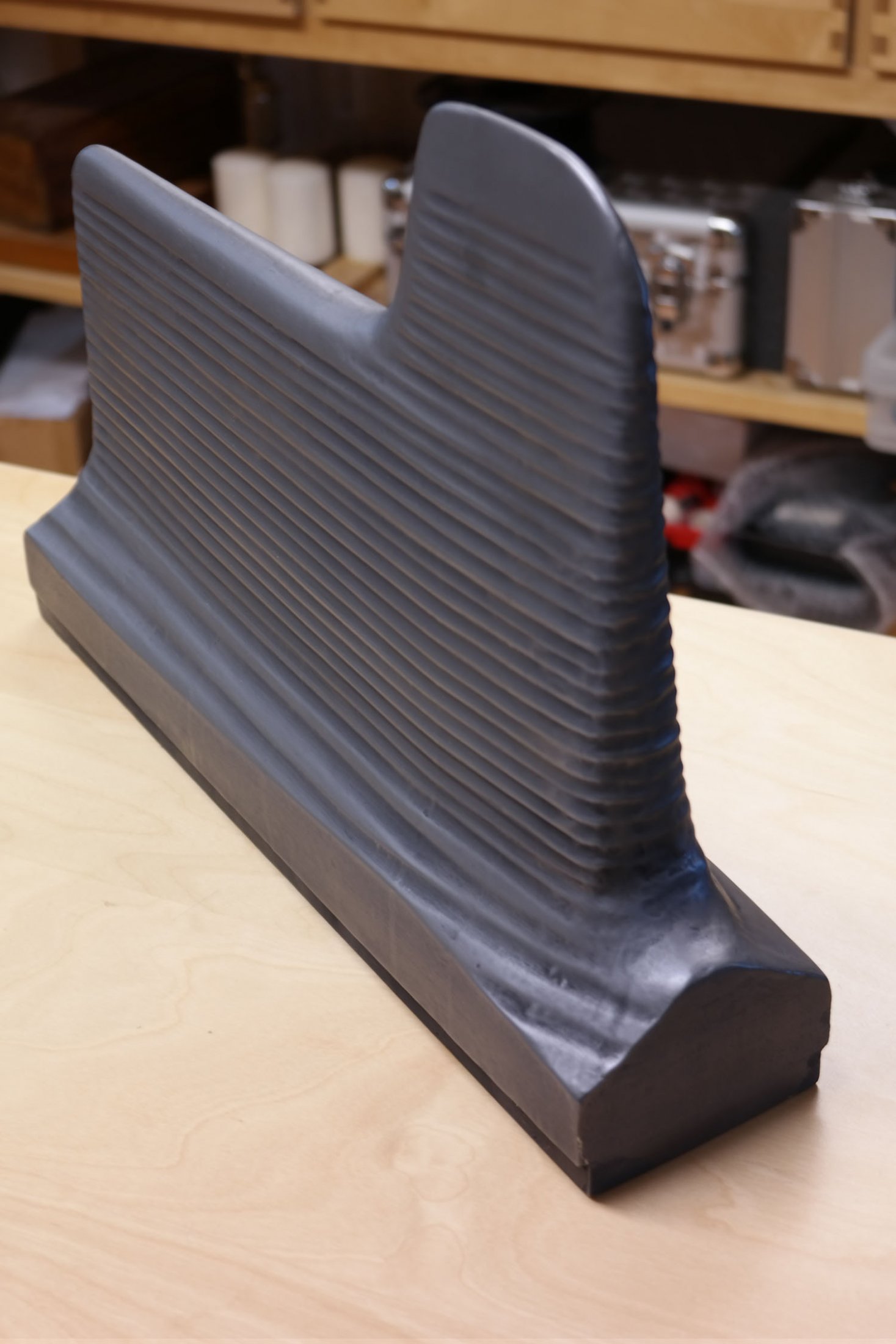
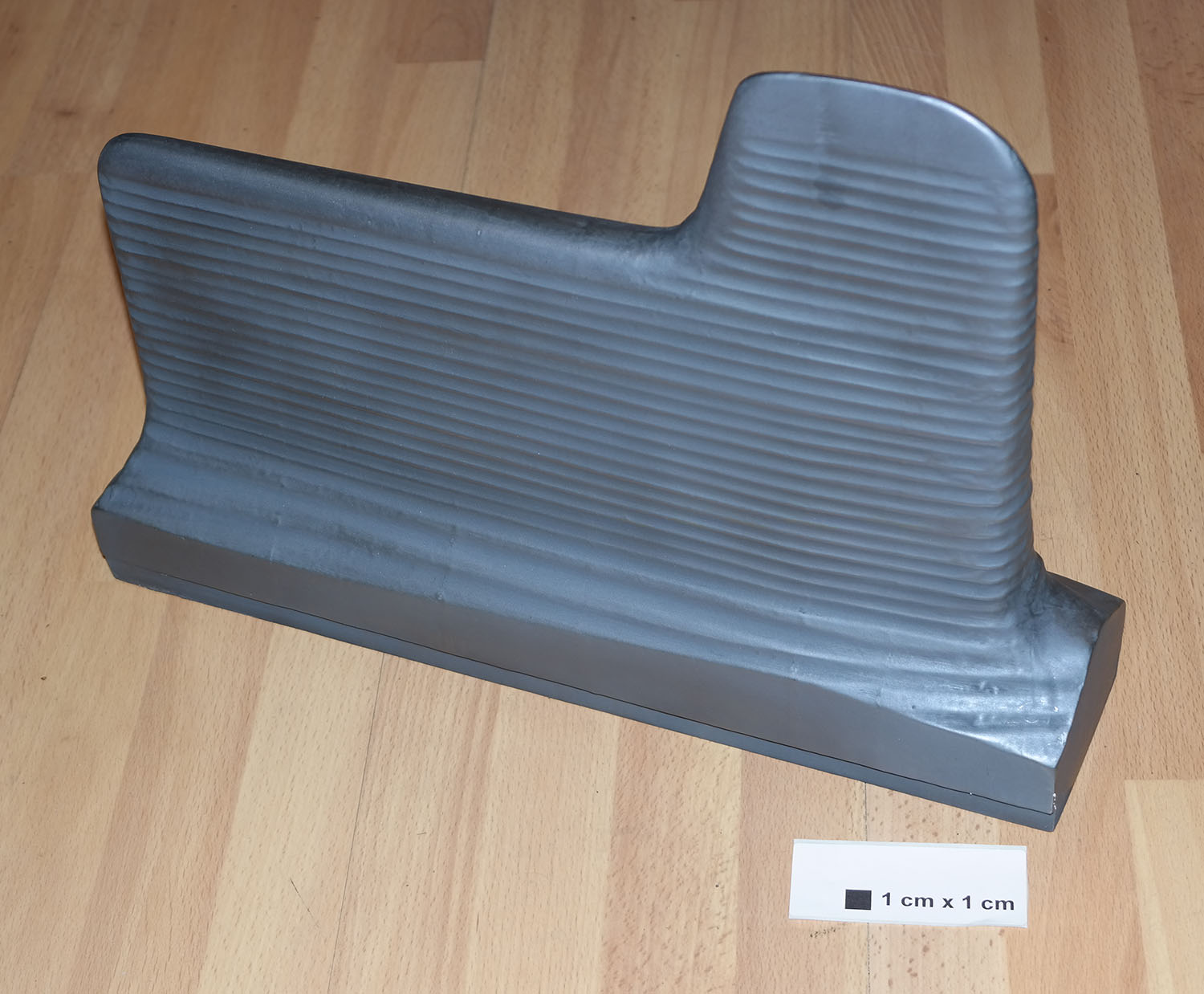
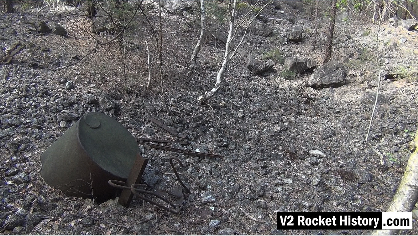
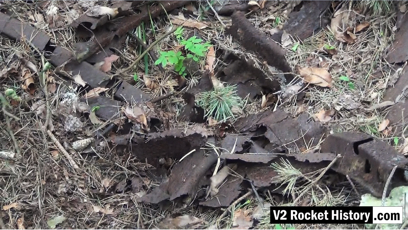
Unknown helical part
Unknown helical part
This part has a helicoid or screw shape, it seems that it might have been designed to screw into a pipe of some kind. But do you know what it really is, and what it did? If you do, please tell us.
| Album | The Enigmas |
| Category | Mystery part |
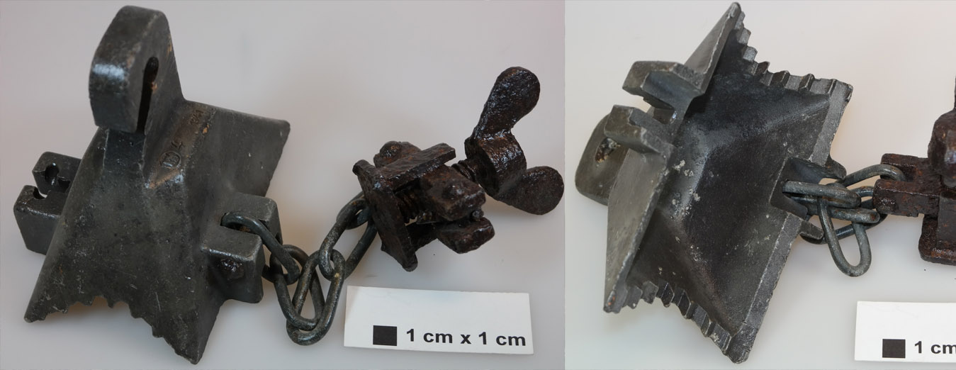
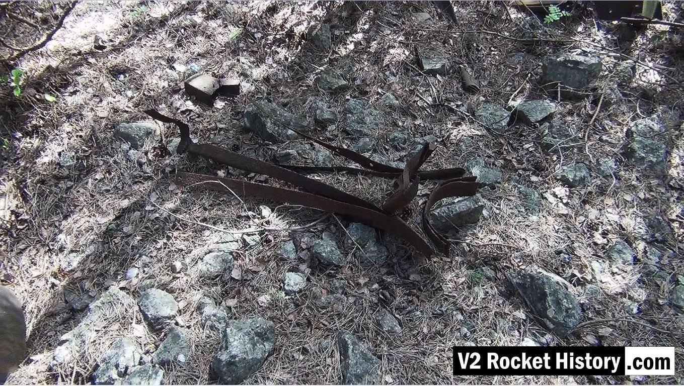
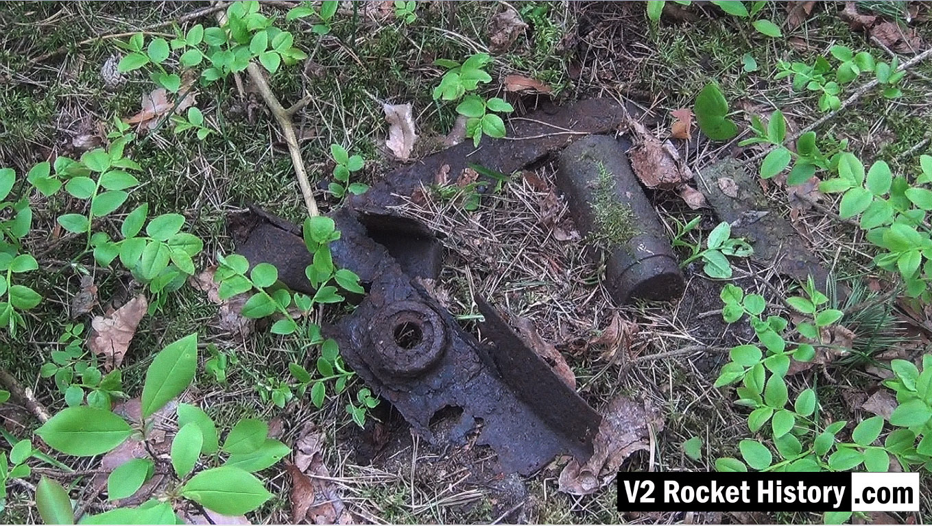
Chain and hook clamp – unknown use
Chain and hook clamp – unknown use
We know this is a clampy-chainy-hooky thing – but do you know what it really is, and what it did? If you do, please tell us.
| Album | The Enigmas |
| Category | Mystery part |
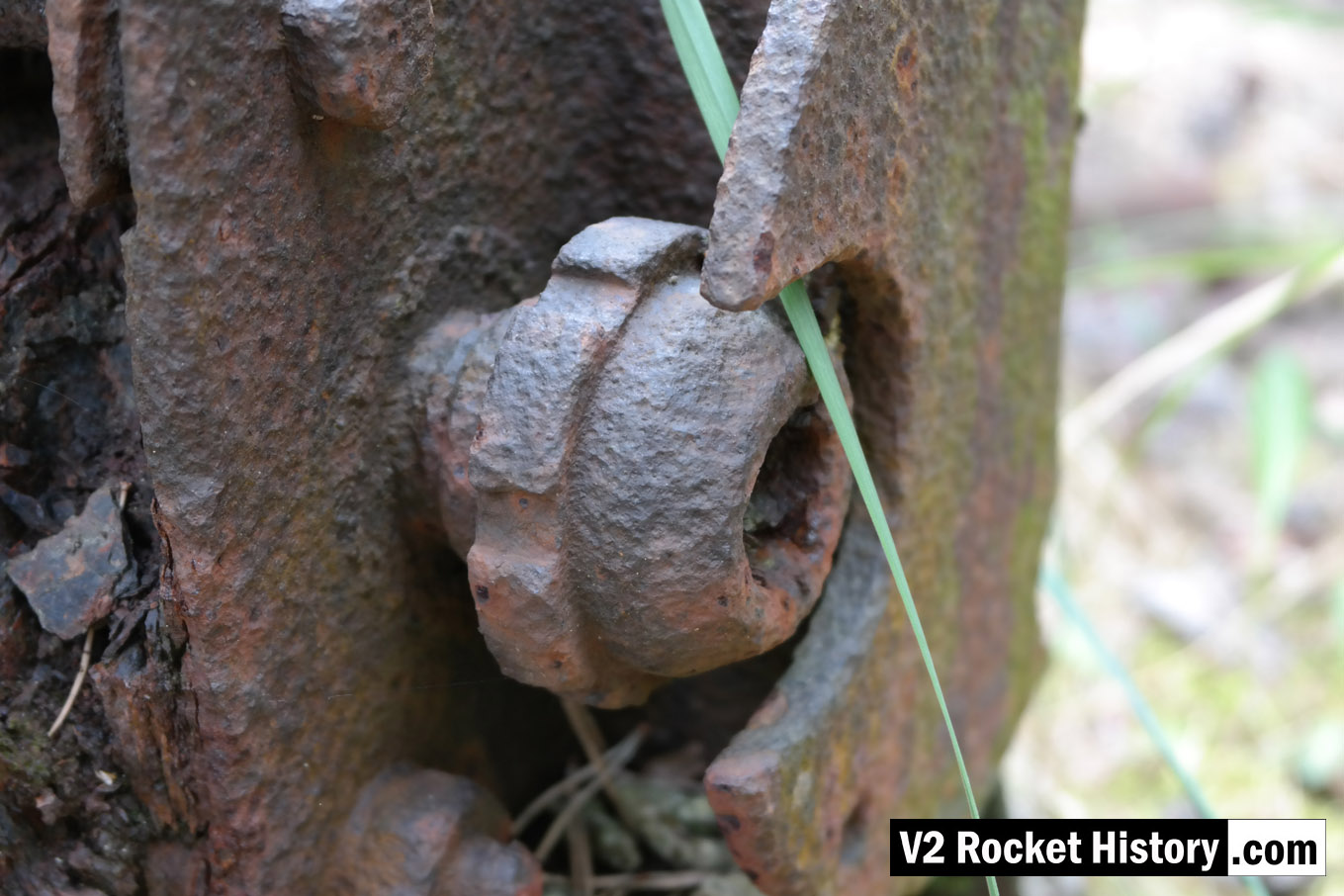
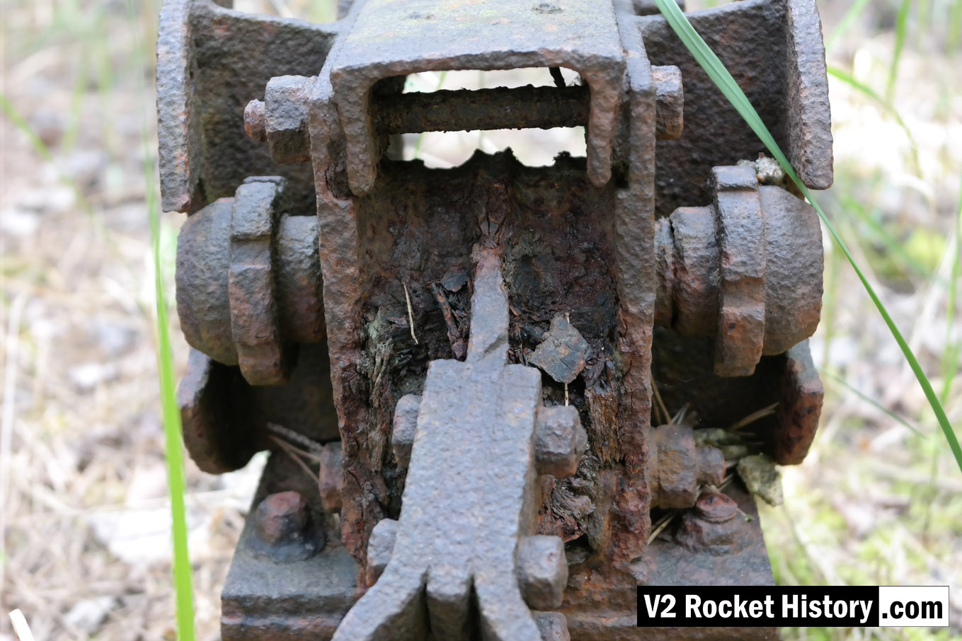
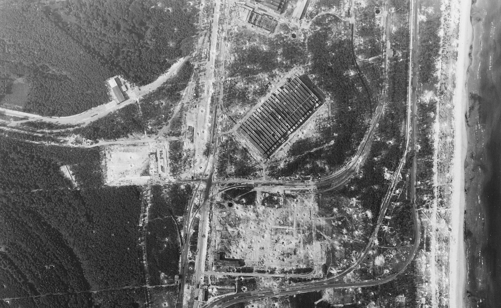
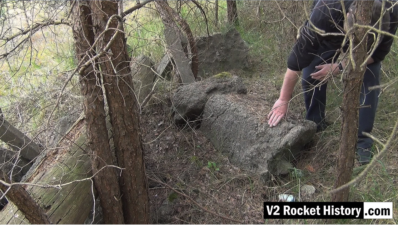
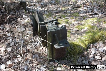
Close up of relic within IW near aisle 20
Close up of relic within IW near aisle 20
This is a close up of the mystery item, referred to on our Enigma page, found firmly anchored to the floor a few metres inside the east wall near aisle 20 of IW (near location of internal railway line).
| Album | The Enigmas |
| Category | Mystery part |
Close up of relic within IW near aisle 20
Close up of relic within IW near aisle 20
This is another close up of the mystery item showing the mechanism in more detail. It can be found firmly anchored to the floor a few metres inside the east wall near aisle 20 of IW (near location of internal railway line). See map below for location.
| Album | The Enigmas |
| Category | Mystery part |
F1: Fertigungshalle Eins
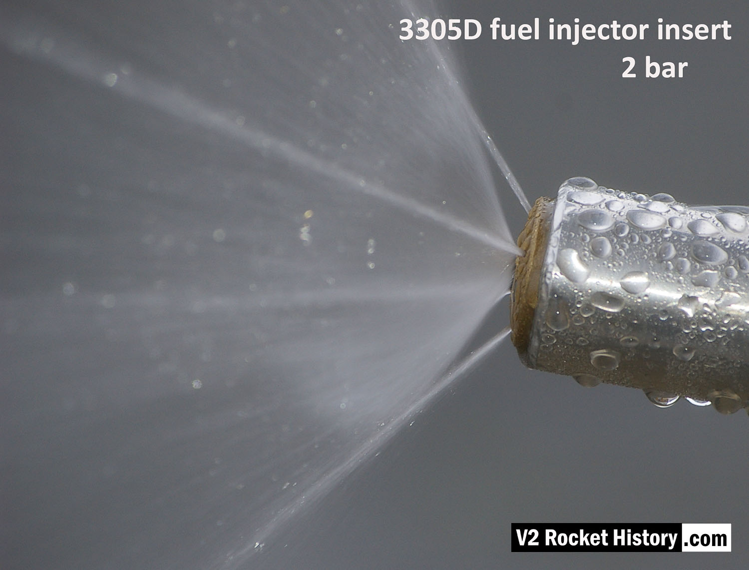
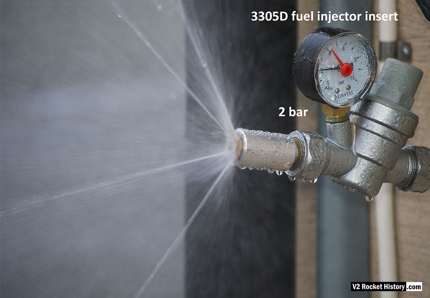
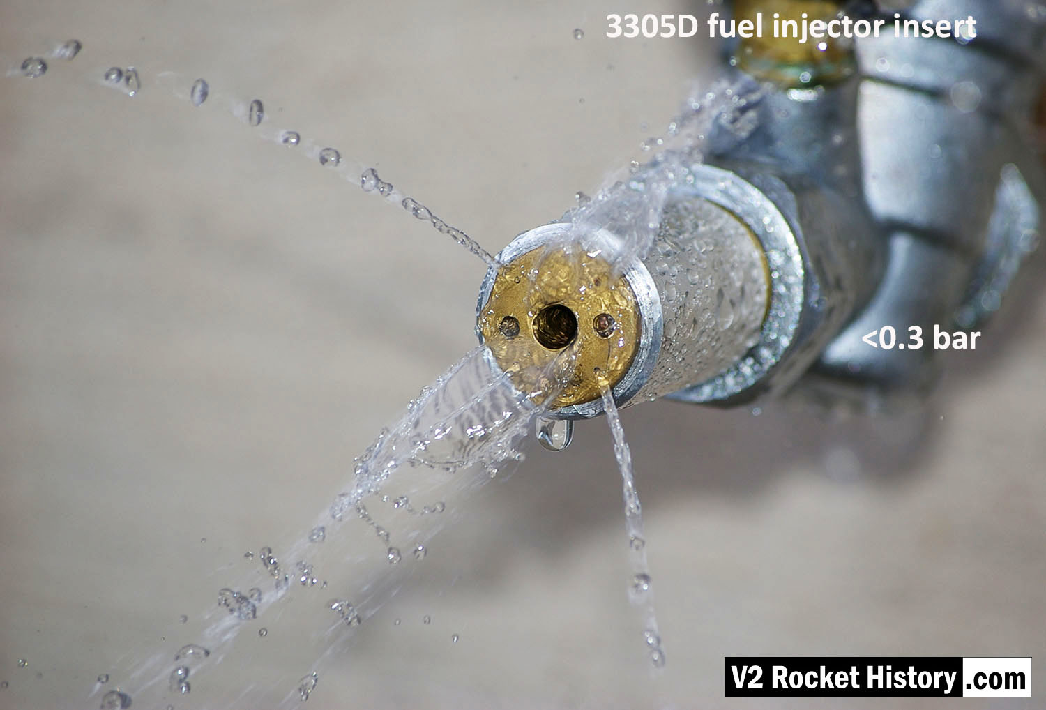
3305D Close-up of nebular cone & cooling jets
3305D Close-up of nebular cone & cooling jets
Image shows a correctly formed nebular cone attended by a fine mist. the four injector cooling jets are well shown, and although fluid beading can be seen on the face of the injector, there is insufficient liquid to cause dripping.
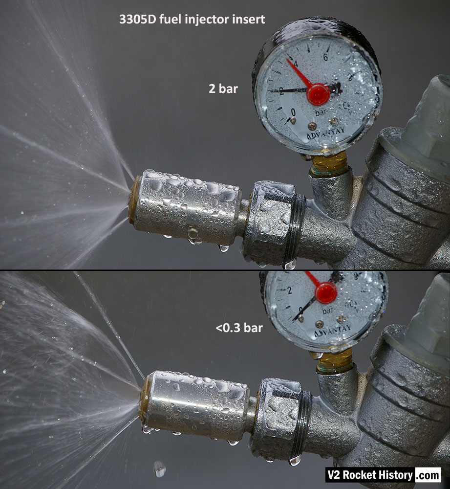
3305D Water Test Comparison
3305D Water Test Comparison
3305D injector insert showing comparison nebular and jet stream pattern with high and low pressure. Top image shows correct hollow cone-shaped aerosol effect, from central 6mm orifice, that is also creating a fine mist around and within the cone, and steady steams emanating from cooling pores. Bottom image shows the effect of reduced pressure: a dropping poorly formed cone, composed of larger slower moving droplets, and a tendency for the thicker spray to combine and cause ‘dribbeling’ with much fluid failing to clear the injector face – unlike the image above, where the injector face is clear of drips.
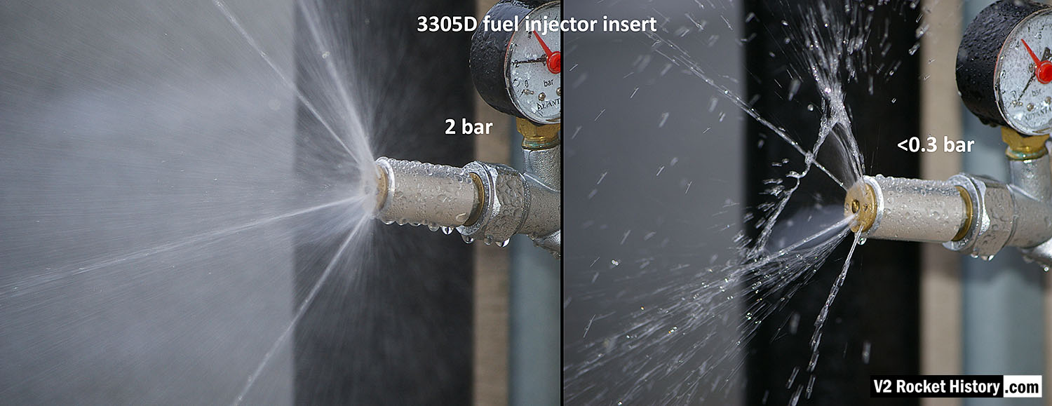
3305D Water Test Comparison 2
3305D Water Test Comparison 2
3305D fuel njector insert showing comparison nebular and jet stream pattern with high and low pressure. Left image shows correct hollow cone-shaped aerosol effect from central 6mm orifice, that is also creating a fine mist around and within the cone, and 4 steady steams emanating from cooling pores. Right image shows the effect of reduced pressure: a dropping poorly formed cone, composed of larger slower moving droplets, and a tendency for the thicker spray to combine and cause ‘dribbeling’ with much fluid failing to clear the injector face.
3305D Water test nebular pattern
3305D Water test nebular pattern
3305D fuel injector insert showing swirl cone nebular, and 4 steady steams emanating from cooling pores.
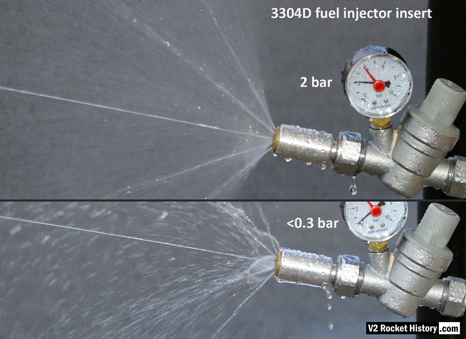
Fuel injector 3304D water test comparison
Fuel injector 3304D water test comparison
3304D higher volume injector insert (with central jet) showing comparison nebular and jet stream pattern with high and low pressure. Top image shows correct hollow cone-shaped aerosol effect from central 6mm orifice, that is also creating a fine mist around and within the cone, and strong single central (non-swirl) jet can be seen as well as 4 steady steams emanating from cooling pores. Bottom image shows the effect of reduced pressure: a dropping poorly formed cone, composed of larger slower moving droplets, and a tendency for the thicker spray to combine and cause ‘dribbeling’ with much fluid failing to clear the injector face. The appearance of central jet however seem largely unchanged.
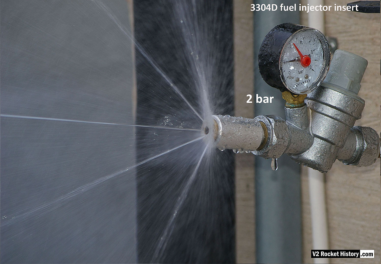
3304D Water test nebular pattern showing central jet
3304D Water test nebular pattern showing central jet
3304D higher volume fuel injector insert (with three inlet apertures: 2 swirl, 1 jet) showing swirl cone nebular, steady central jet, and 4 steady steams emanating from cooling pores.
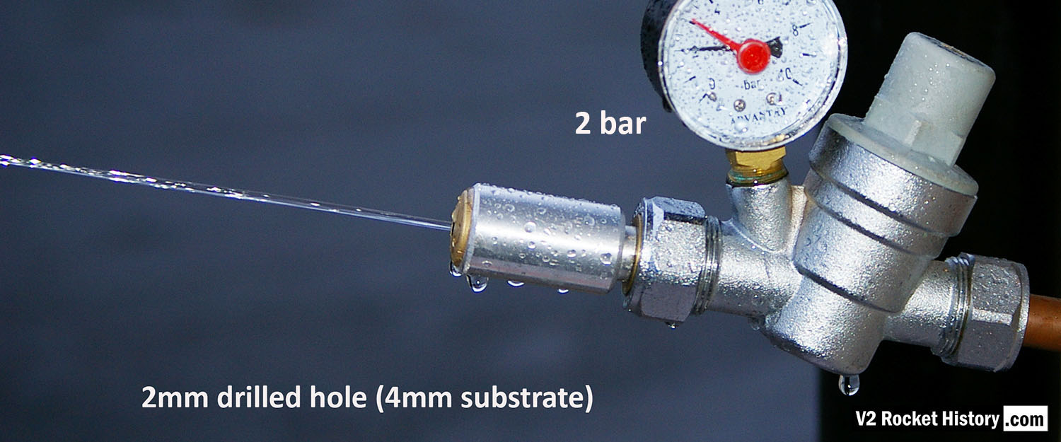
Jet from 2mm drilled fuel feed hole
Jet from 2mm drilled fuel feed hole
Each burner cup of the V2 rocket engine injector system has forty-four brass inserts, but each cup also has twenty-four 2mm diameter plain holes, 30 deg apart, drilled into the cup’s central wall. To mimic this for testing purposes, we created a brass insert that has a base with just a 2mm central hole. The base is sized to be consistent with the 4 to 5mm cup wall. V2RH image
3305D Water Test Pattern
3305D Water Test Pattern
3305D injector insert showing larger low-velocity droplets and ‘dribbly’ performance due to insufficient pressure. The cone shaped aerosol is not functioning. Broken streams can be seem emanating from the four cooling pores.
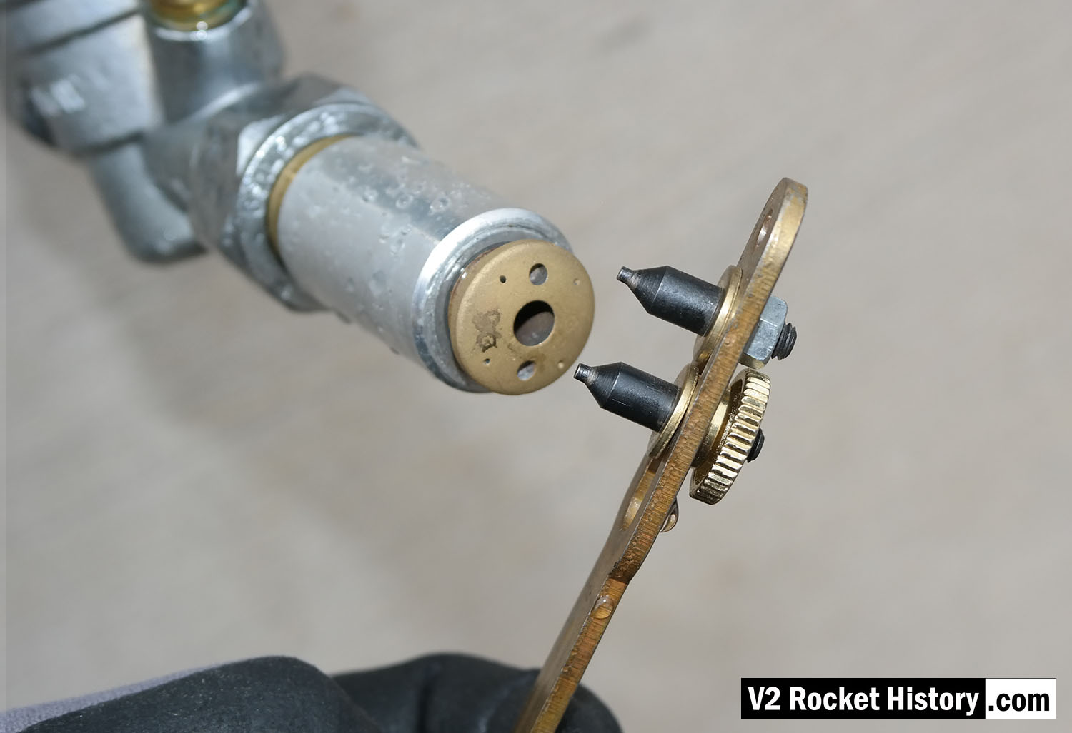
Injector test rig showing pin wrench to fit inserts
Injector test rig showing pin wrench to fit inserts
Single fuel injector water test rig showing a 3305D bress insert about to be tightened home using a pin-wrench. V2RH image

V2 fuel injector Insert test rig
V2 fuel injector Insert test rig
Single nozzle insert test rig used by V2 Rocket History to test spray shape and volume at supply pressures consistent with fuel pressures specified for the injector head of summer 1944. The test system features an adjustable pressure regulator and fluid pressure gauge. For test purposes the device was simply connected to a relatively high pressure mains water supply. And although water does not have the same viscosity of the 75% Ethenol to 25% water mix of the V2’s fuel it was considered close enough by the German technicians, who regularly used plain water as a substitute when testing issues related to furl flow rather than combustion. A 2131E fuel injector insert is shown installed in the holder at the front of the rig, but as the thread was the same on all inserts the nozzle can be changed for other models easily with aid of a pin spanner. See video for a demonstration of this simple test system.

Test Rig With E Type Insert
Test Rig With E Type Insert
Single nozzle insert test rig used by V2 Rocket History to test spray shape and volume at fluid supply pressures consistent with fuel pressures specified for the injector head of summer 1944. A 2131E fuel injector insert is installed in the holder at the front of the test rig, but as the thread was the same on all inserts the nozzle can be changed for other models easily with aid of a pin spanner. See video for a demonstration of this simple test system.

Fuel injector flow test results
Fuel injector flow test results
The chart shows water delivery in litres per minute per injector
| Album | Testing fuel injectors |
| Categories | Combustion, Propellant flow |

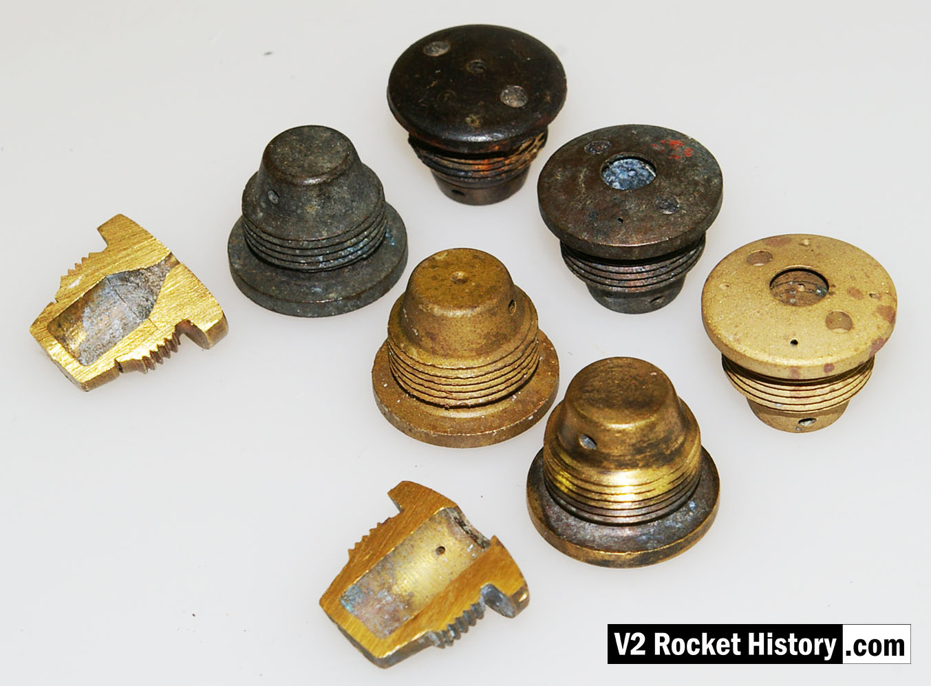
V2 Fuel Injector insert test stock
V2 Fuel Injector insert test stock
V2 rocket engine fuel injector inserts – a part of our collection used for the water tests with various types shown. The tool shown is a pin-wrench used to fit the inserts into the test apparatus. V2RH collection image

Fuel Injector insert showing aperture details
Fuel Injector insert showing aperture details
Standard fuel injector inserts for production series 18-pot injector head. Insert 1 (3304D/3305D) shows four thin wires demonstrating the angles of all four ‘cooling’ pores. Insert 2 (3305D/2131E) has two 1.3mm twist drill showing the edge bores for the gyroscopic swirl inlets. Insert 3 (3305D) shows another view of the cooling pore angle and origin. V2RH image

V2 Fuel Injector 2131E
V2 Fuel Injector 2131E
V2 Fuel Injector insert: part code 2131E from injector pot echelon A (nearest to LOX spray head). The push-together two part construction of the insert is shown here. The two parts were pushed together in a specially shaped tool set that compressed the thin skirt on the female part into a recess cut into the male part. The failure test for this component required that the mated parts resist a separating force of 300kg. The two part design was dictated by the small size of the 2mm exit orifice and the funnel shaped introduction to the exit orifice. In the case of the other three standard inserts, the large 6mm exit orifice allowed a sub 6mm milling cutter, with a thin support shaft and a top chamfer, to be used in such a way that the area below the exit orifice could be undercut to create an injector cavity with a diameter larger than the 6mm entry point.
Swirl nozzle insert set 2
Swirl nozzle insert set 2
Fuel injector inserts for production series 18-pot injector head showing general shape and thread position. For further details see associated image. The lowermost insert have been halved to reveal the cavity shape, orifice edge, inlet and cooling apertures. V2RH image
Equipment bays
Control compartment 3
Control compartment 3
Control compartments 3 showing gyro mounting platform with two gyros and DC motor driven 3 phase AC voltage generator. The alcohol tank pressurisation pipe is also shown running through the equipment bay (large silver coloured pipe). Image copyright Imperial War Museum
| Album | Equipment bays |
| Category | Guidence |

Ernst Steinhoff
Ernst Steinhoff
Ernst Steinhoff, chief of the BSM workshop (Guidance and Control) in the development works Peenemunde.
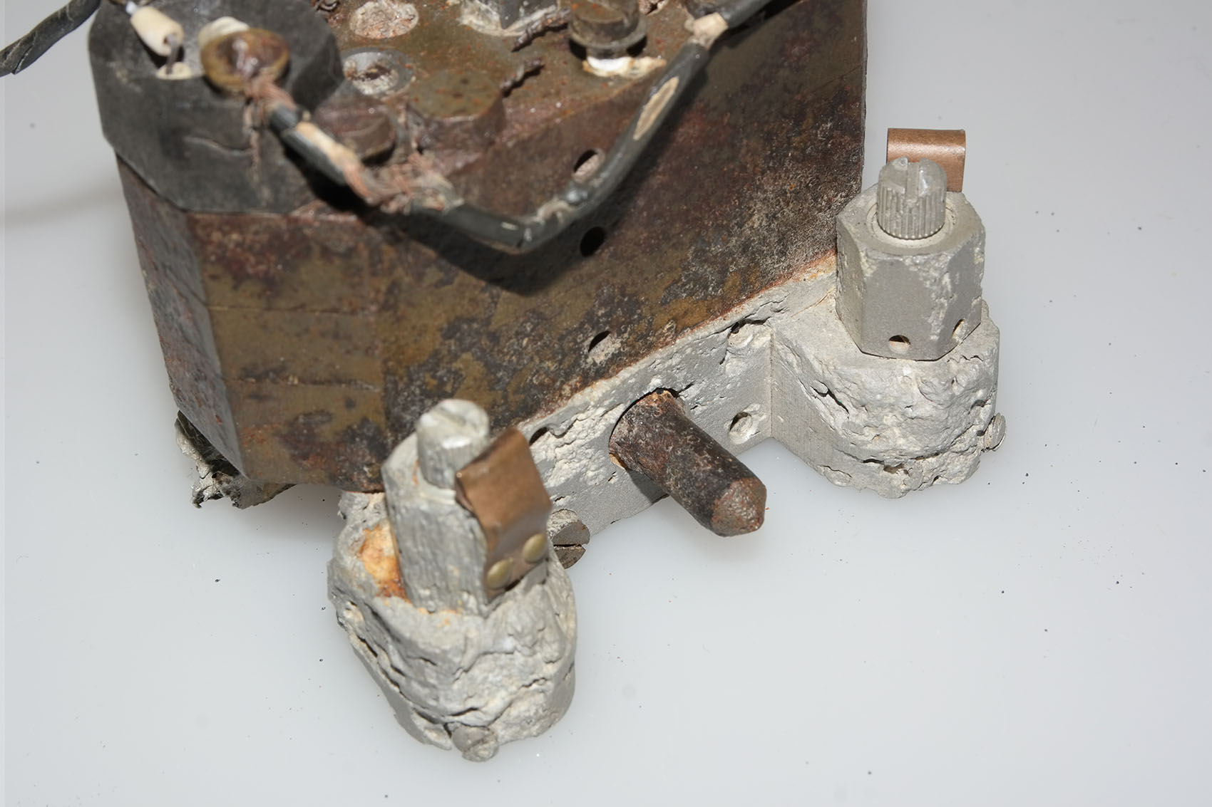
Gear pump detail showing ceramic insulator with nichrome element
Gear pump detail showing ceramic insulator with nichrome element
Hydraulic gear pump with close up detail showing ceramic heater element insulators with flat, possibly nichome, metal strip element threaded through them. This oil heating system was designed to maintain a specific viscosity of the oil regardless of environmental temperature, to better maintain oil flow rates and thus pump efficiency. The heating system is found only rarely on surviving relics.
Graphite jet vane replica
Graphite jet vane replica
V2 missile graphite jet vane defector replica made for V2 Rocket History.
Graphite vane rocket jet deflector replica
Graphite vane rocket jet deflector replica
V2 missile graphite jet vane defector replica made for V2 Rocket History. This accurate replica shows the distinctive pantograph mill tool ‘witness’ marks well.
Hydraulic gear pump detail
Hydraulic gear pump detail
Close-up of Askania gear pump relic with oil heaters. This picture shows an unusual feature on the otherwise normal cast aluminium base of this gear pump. The knurled knob positioned between the oil flow balance adjusters has a purpose that is unknown to us. The two oil-flow balance adjuster valves visible in the picture have slot head adjuster screws and you can also see the knurled circumference on each screw. This parallel knurling is engaged by a crease formed in the facing surface of the copper spring strips. The function of these strips is to create tactile feedback that the technician making the adjustment can feel in the handle of the screwdriver. This was done because the gear pump needed to be adjusted in a dark and narrowly confined space.
Gear pump showing flow adjusters and ceramic heater elements
Gear pump showing flow adjusters and ceramic heater elements
Gear pump showing flow adjusters (two slot head screws nearest bottom of picture) and ceramic heater elements situated at each end of the block. The square drive shaft coupler (corroded but still identifiable) has been highlighted in red paint. The open holes either side are the main control valve guides. The copper spring strips visible on each oil flow adjuster provide locking and tactile feed-back for the adjusting process. This relic was recovered from Usedom island.
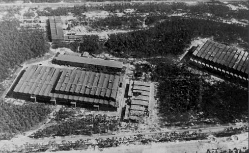
Missile guidance equipment
Images of guidance and missile control equiment


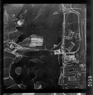
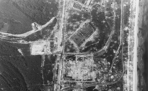
Peenemünde-Usedom-locations
Locations on Usedom island, Germany, of historical significance to the development of the V2 missile.
Categories: Peenemünde-Usedom-locations, Production plant (Versuchsserienwerk), V2 Missile relics, Guidence
Tags: #Fertigungshalle Eins (F1) #IW Repair & Maintenance Hall (R&MH) #Werk Sud (South Works) #Peenemünde #HAP #HVP #V2 Missile relics #Usedom #Steam generator #Karlshagen #light beam device #People
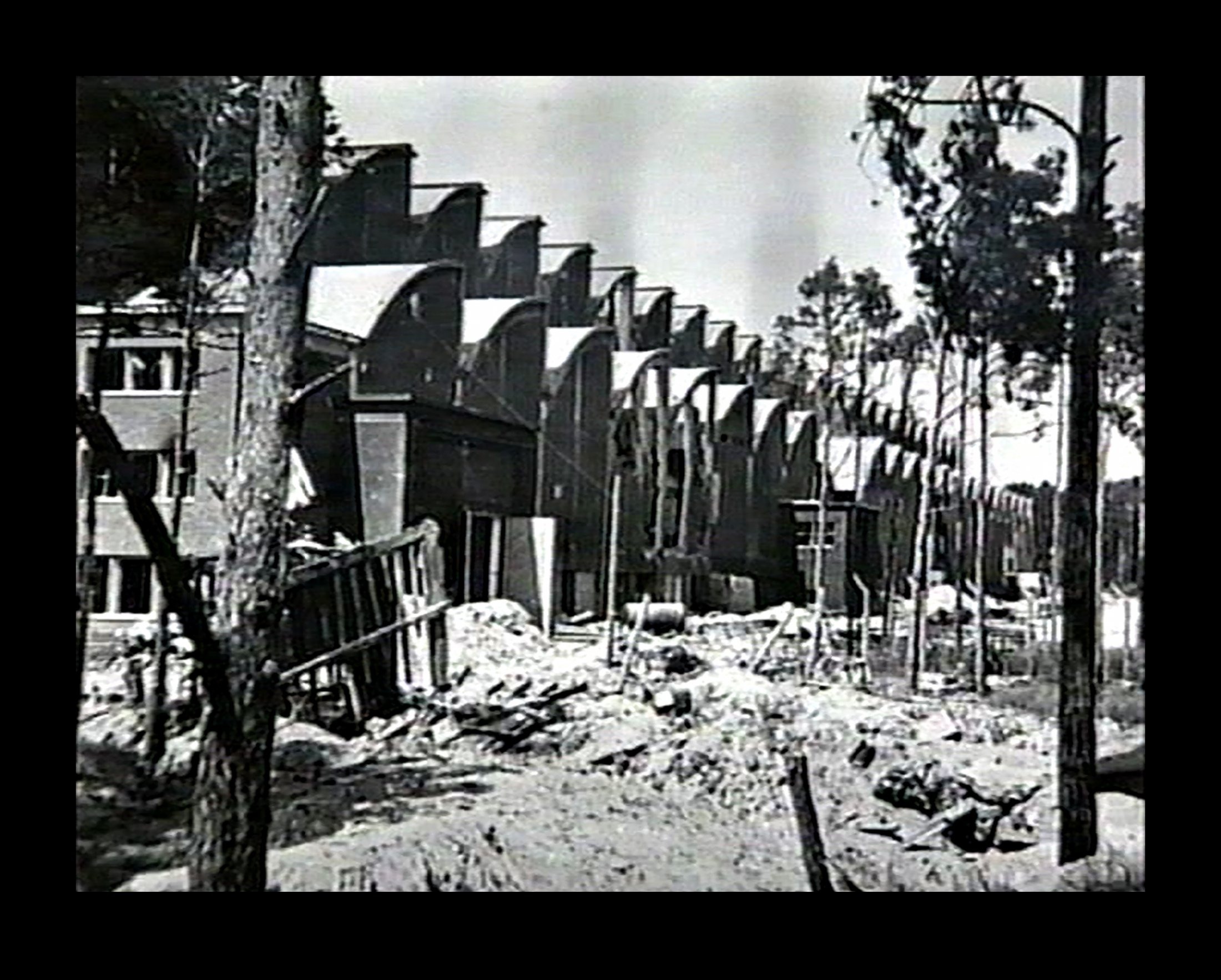
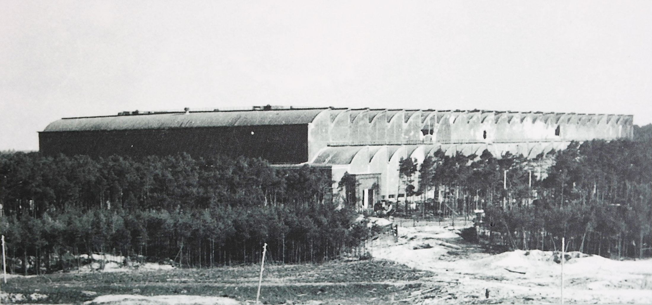
IW and F1 on 19th August 1943


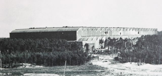
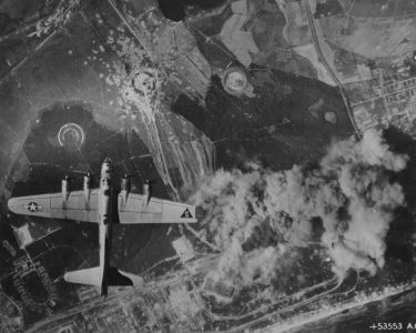
Description
Photo showing Werk Süd with IW on the left and F1 on the right taken on 19th August 1943. The photo shows only light damage to the main halls, although F1 was actually hit at least 11 times, and hits to the separate single storey workshops to the right of the IW hall. The long storage (oil and paint?) shed above IW and the woodworking shop at the top of the picture appear undamaged. Anti-aircraft platforms (at least 3) can be seen on the roof of IW but that seem to be empty of guns. F1 shows two AAA platforms (there was at least 3 at this stage and maybe more) and they may have guns installed. General W. Dornberger mentions defensive AA artillery fire from the from the roof of F1 in his 1952 book V2 (1954 in English).
Location
