Archives: Gmedia Albums


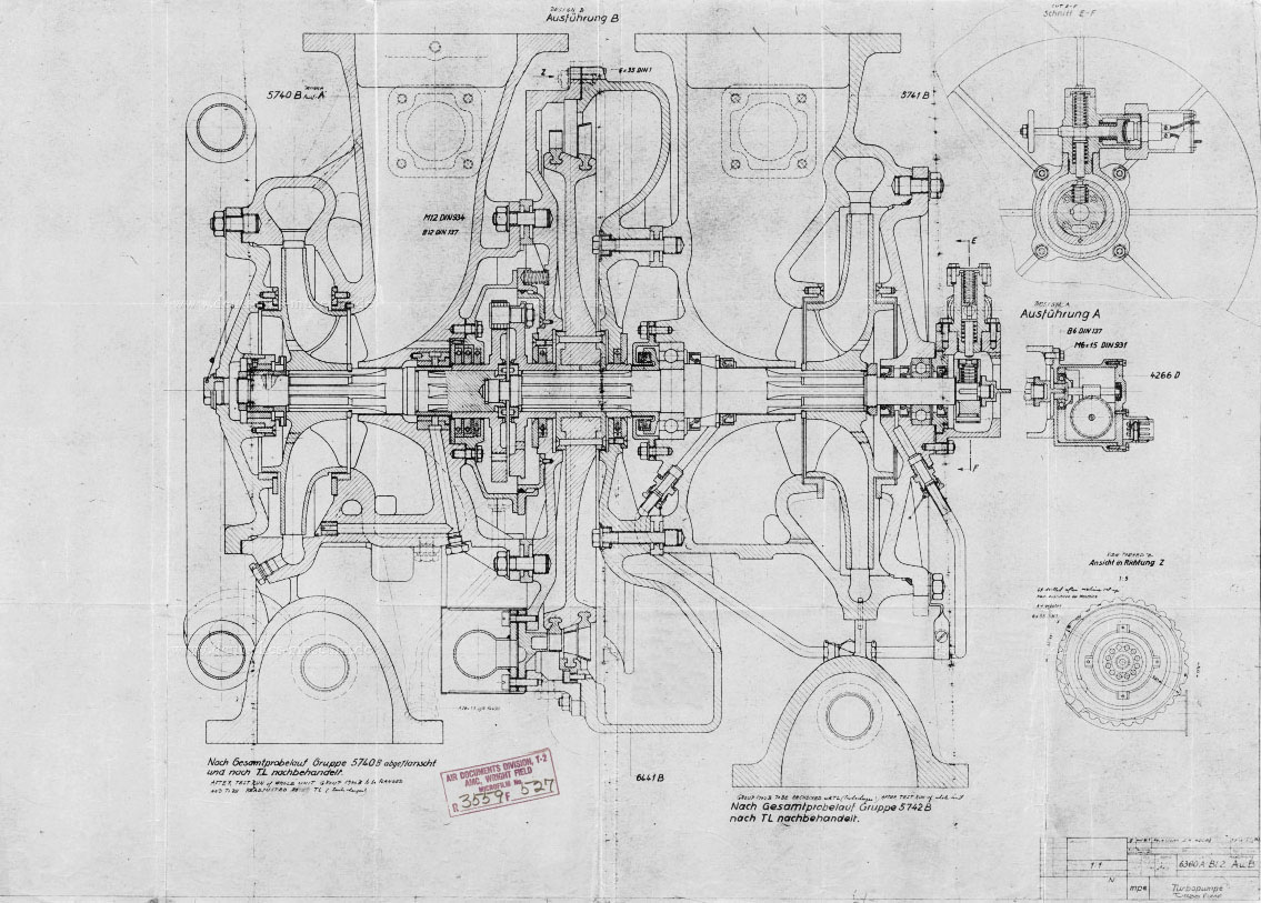
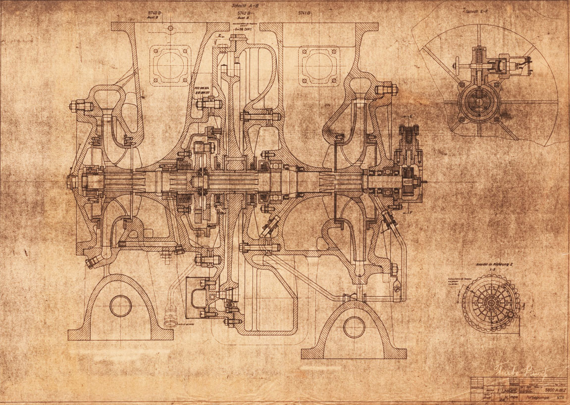
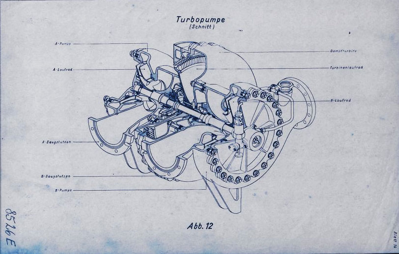
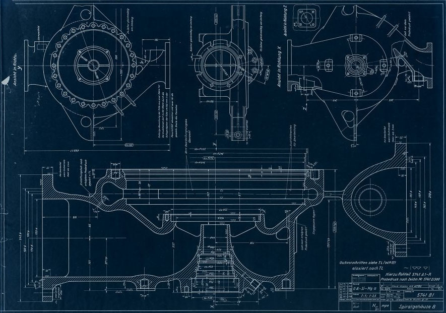
Turbopump 3D CAD
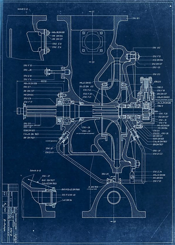
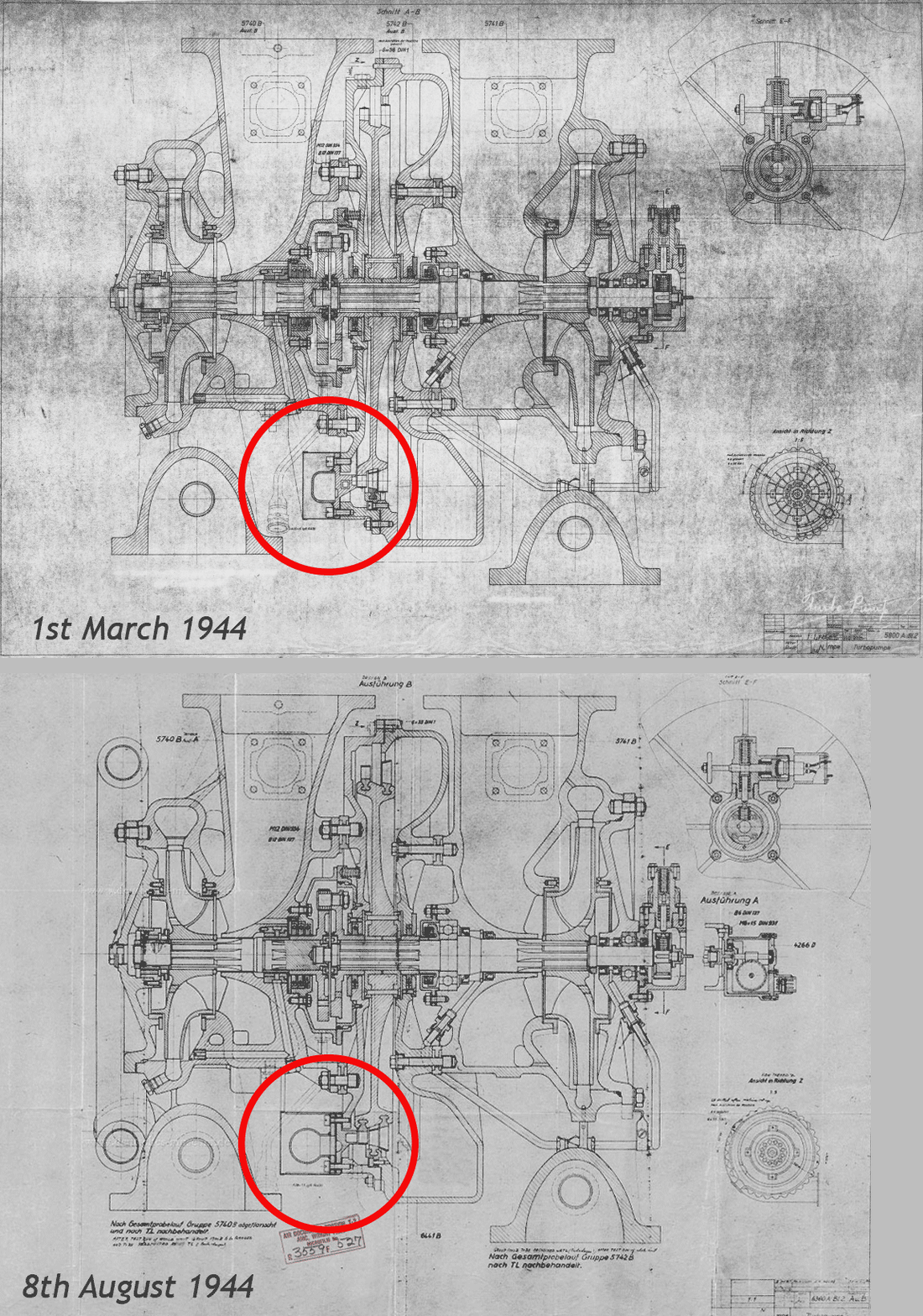
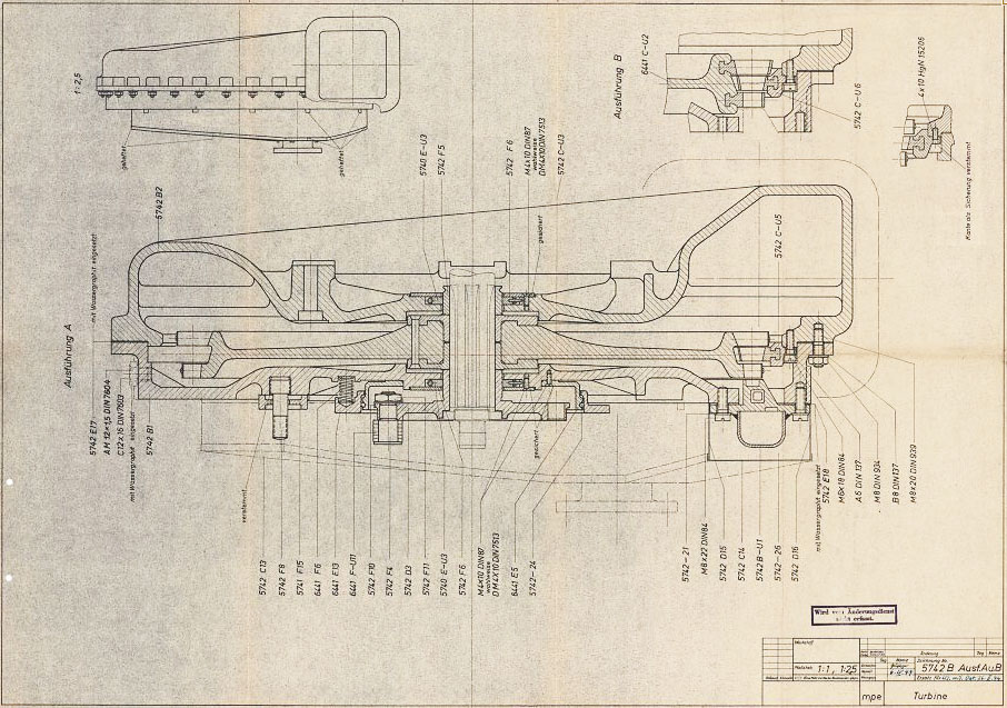
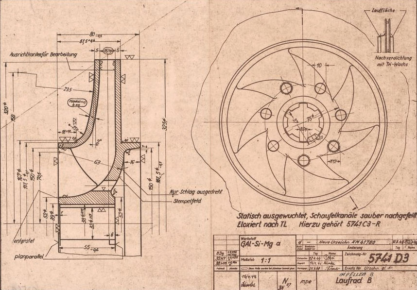
3D CAD model images of the A4/V2 rocket engine’s steam turbine powered propellent pumps – all images by Ray Matter. To see Ray Matter’s blog 3D CAD modelling the V2 rocket turbopump introducing these images, just click the link.
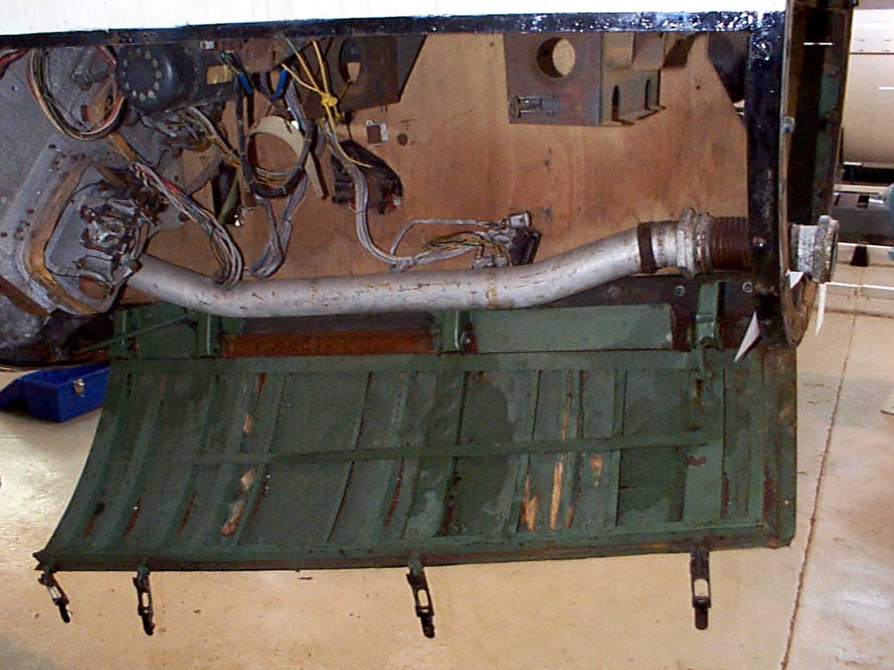
Control compartments 3 showing gyro mounting platform with two gyros and DC motor driven 3 phase AC voltage generator. The alcohol tank pressurisation pipe is also shown running through the equipment bay (large silver coloured pipe). Image copyright Imperial War Museum
| Album | Equipment bays |
| Category | Guidence |
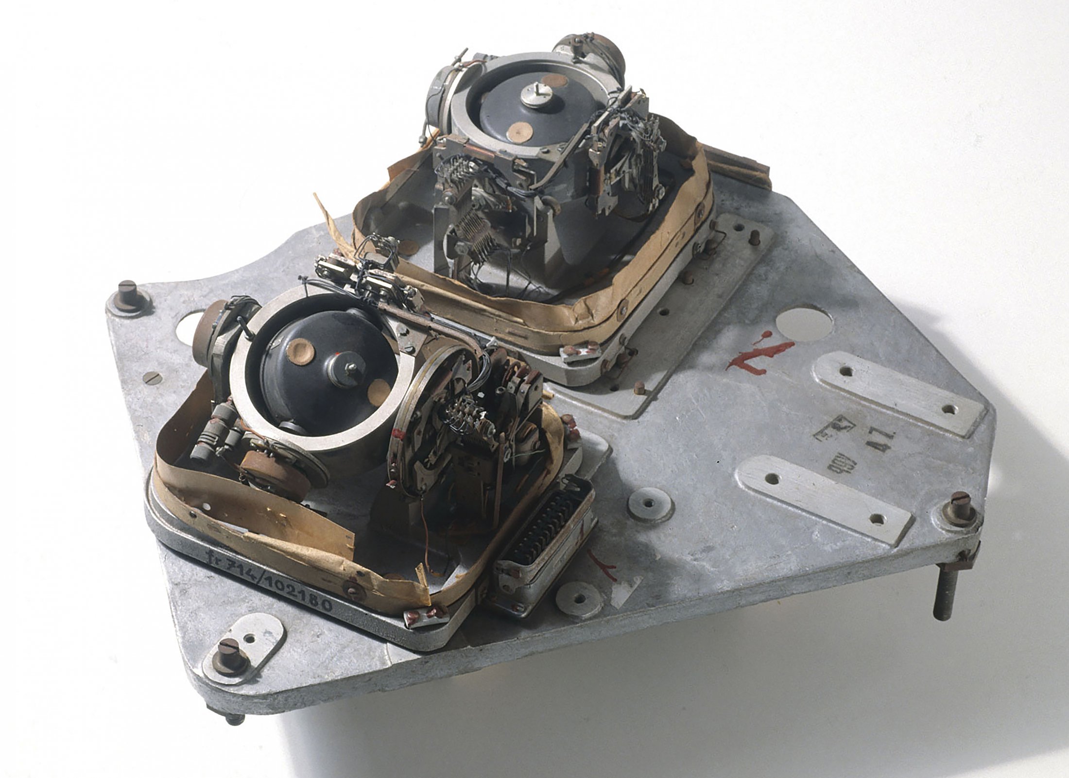
LEV-3 V2 missile gyroscope system with mounting plate. The third component of this system, the Muller gyroscopic accelerometer, is missing – the 2x mounting points can be seen on the right-hand side of the mounting plate.
| Album | Missile guidance equipment |
| Categories | Missile guidence, Sub-assemblies |
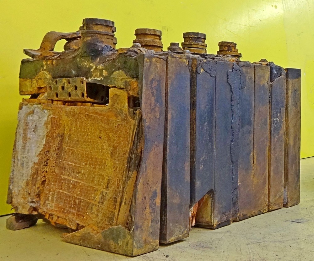
Photo shows rare surviving complete set of 8 lead acid battery cells from one of the V2 rocket’s 32 volt (100 amp) lead acid batteries. Two sets of batteries like this were used to provide the direct current (DC) voltage used aboard the V2 missile to power the DC to 3-phase alternating current (AC) generators, that in turn, powered the gyroscopes, electro-hydraulic servos, trim motors and other vital guidance and control devices. Photo copyright: The Horst Beck Collection
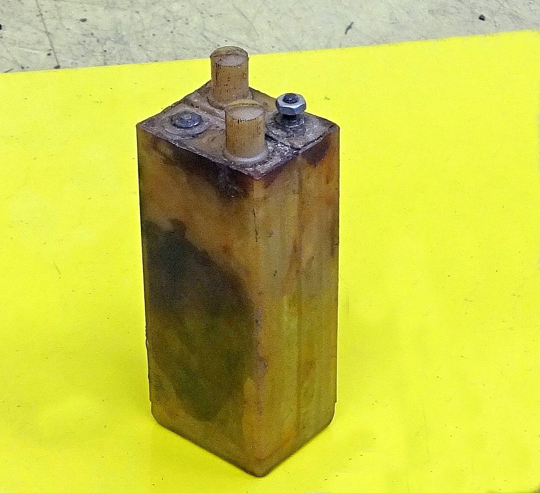
Photo shows rare surviving 1.2 volt cell from the V2 missile’s 50 volt command or signalling battery used in its gyro guidance system (note, the terminal connection on the left is missing from this exhibit, it would be identical to the one on the right). This wet nickel-cadmium battery cell was combined in pairs to a total set of 21 providing a 50.4 voltage at 300mA. The cells were contained in a wooden box that was held on a rack in equipment bay III. Its function was to provide the direct current (DC) signalling voltage that communicated the moment to moment resistance of the gyroscope’s potentiometers to the analog guidance computer (Mischgerät = Mixer-device or control amplifier) aboard the V2 missile. It was critical that the signalling voltage was maintained between 48 and 50.4 volts. Photo copyright: The Horst Beck Collection
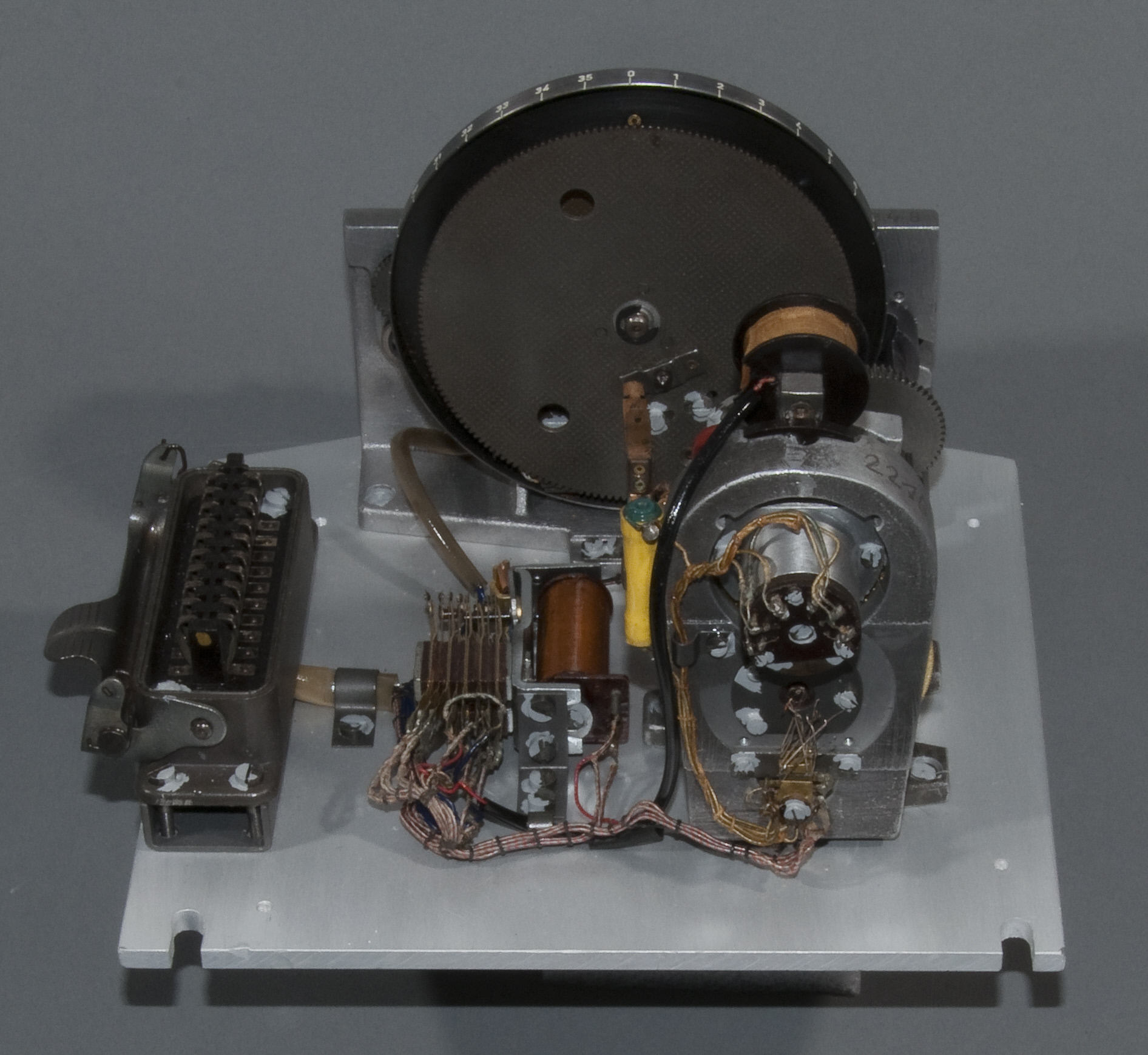
The Muller mechanical or Pendulous Integrating Gyroscopic Accelerometer – today normally referred to as a PIGA. Designed by Fritz K Muller.
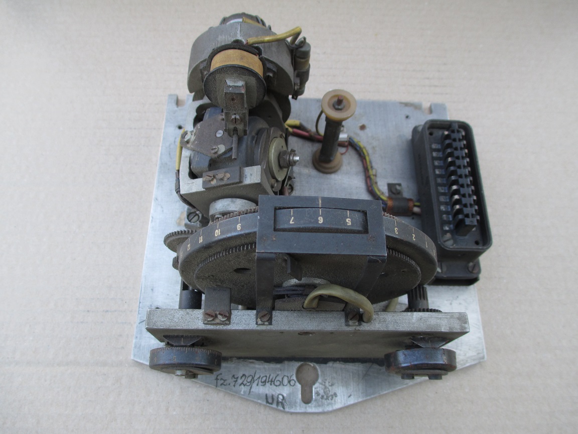
The J device no1 (J Gerate Eins). The full name of this device is: the Muller Pendulous (or mechanical) Integrating Gyroscopic Accelerometer – today normally referred to as a PIGA. The device, designed by Fritz K Muller, operates as a switch to initiate rocket engine shutdown and is able to smoothly record and accumulate every moment of acceleration, without any kind of recording resolution or discrete time interval limit, of the rocket’s entire motor burn phase, and at the same time process this accumulated acceleration with respect to time as a gradually increasing velocity. In the case of the V2 missile, when the correct predetermined velocity is reached, the velicity sufficient to achieve the desired range of the missile, the device trips the relays that close valves that shutdown the supply of steam to the turbo-pump, and thus shutdown the rocket motor itself.

Valves
Images of the main valves involved in the propellant flow of the A4 / V2 liquid fuelled rocket engine
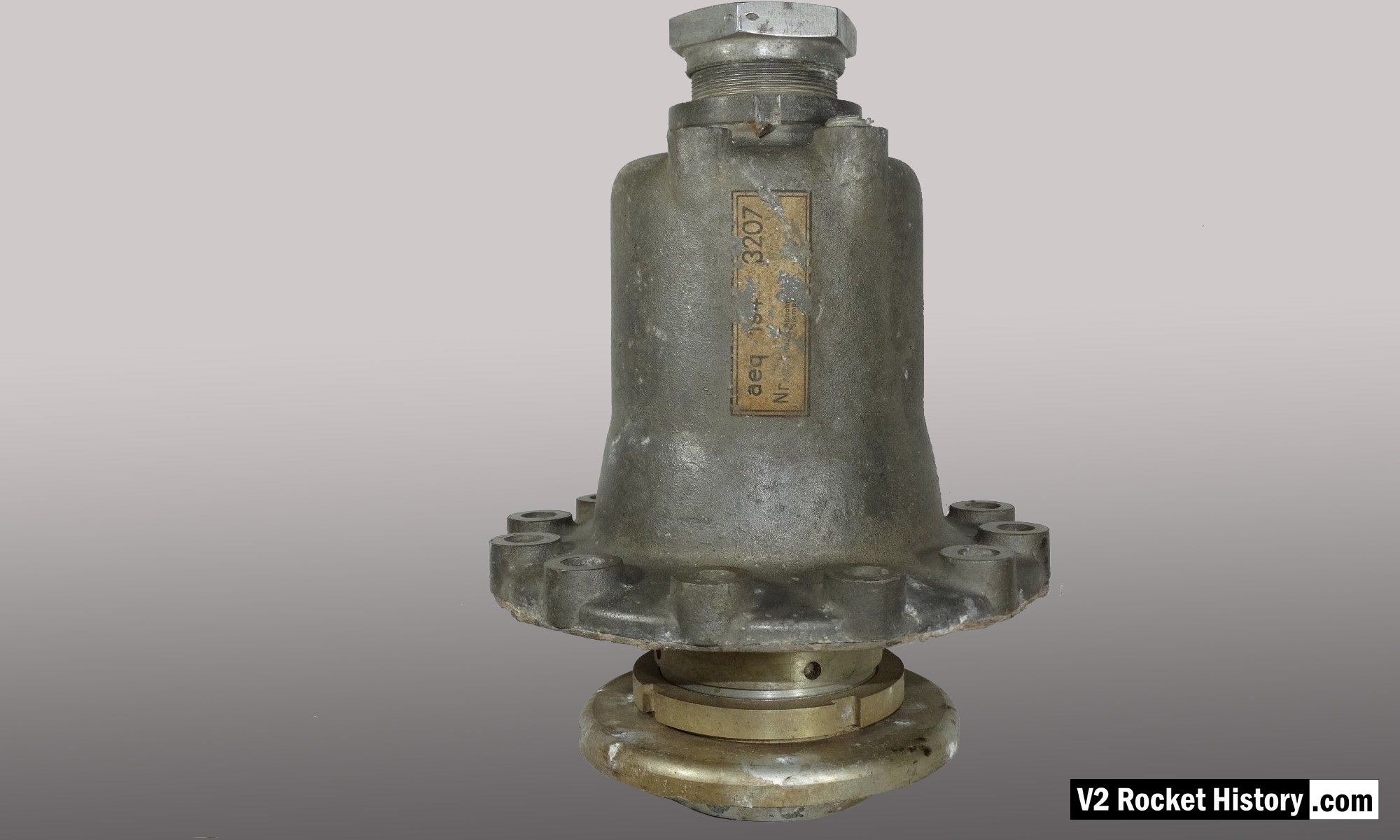
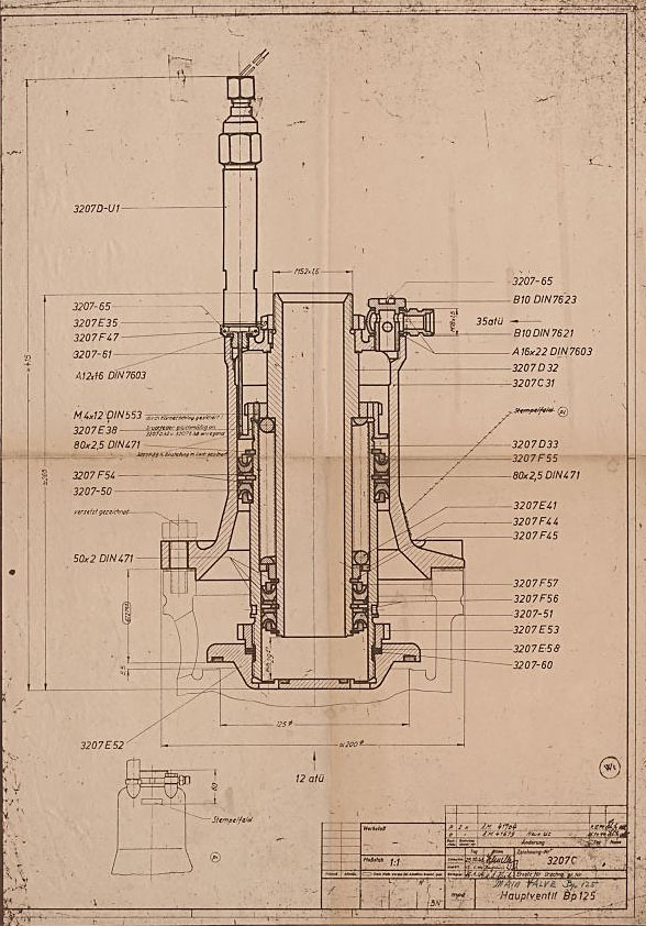
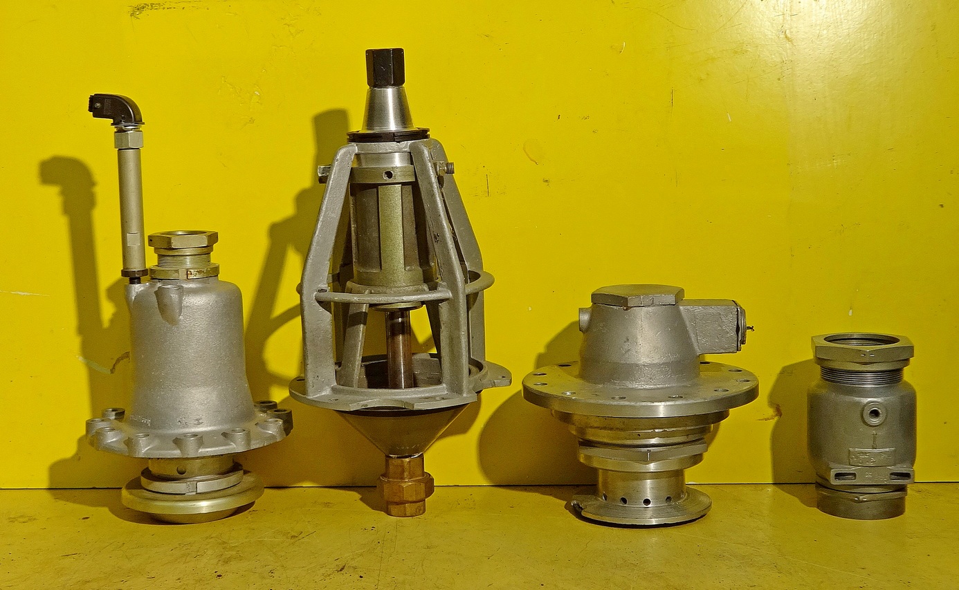
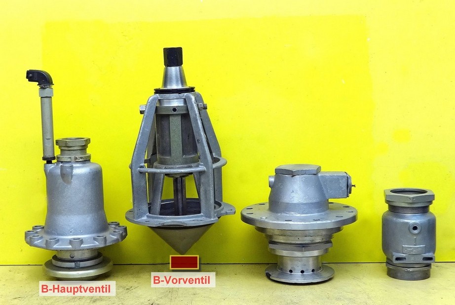
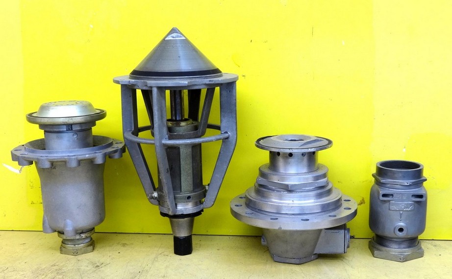
Images of the main valves involved in the propellant flow of the A4 / V2 liquid fuelled rocket engine
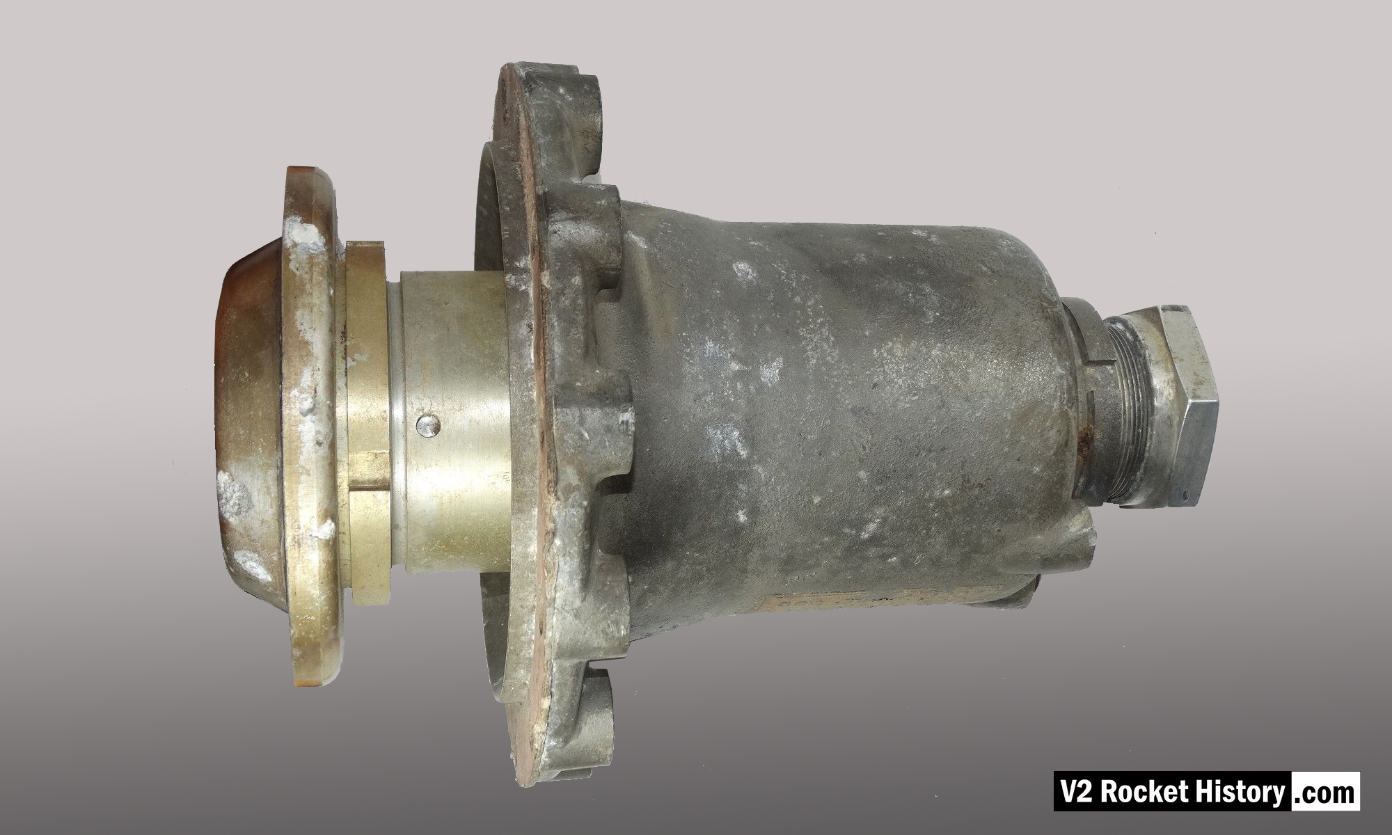
Relic of main alcohol valve with manufacturer code aeq (aeq = Bartoc & Co., Maschinenfabrik u. Giesserei Hedwikow,bei Caslau (Caslav) Czech Republic). An air (nitrogen) inlet pressure of 440 to 530 psi (30 to 36 Bar) was required to close this valve against its internal spring and the force of the turbo-pump. The large nut at the top is the connection for the fuel return (or ‘revolving’line) pipe, and the air and electrical input ports can be seen to the right (air), and left (elec.) just below this point. V2RH image

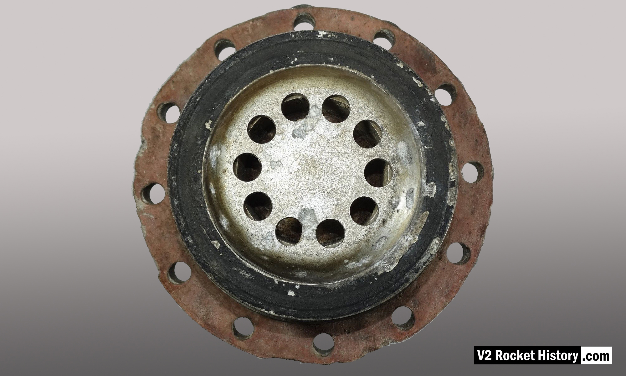
Anatomy of the V2: 18-pot injector head
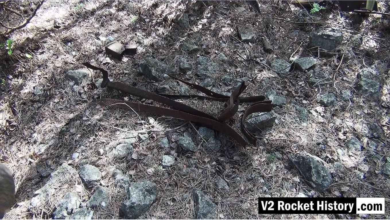
Picture shows parts of V2 missile fin structure laying on open ground near area between admin offices and F1 (near Admin. block railway platform, see map).
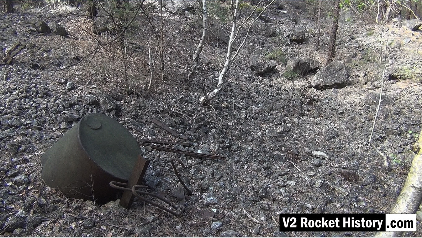
Picture shows metal debris within the F1 factory boundary walls. The purpose of the part buried liquid storage vessel in the foreground is unknown but it is not a vessel capable of being pressurised. Other assorted metal debris include pipe and cable wall cleats, as well as steel armature rods from reinforced concrete castings (powerful demolition explosions have freed the steel rods from the concrete). These reinforcement rods are a common sight in the environs of Fertigungshalle Eins (F1) and the nearby Repair & Maintenance Hall (R&MH).
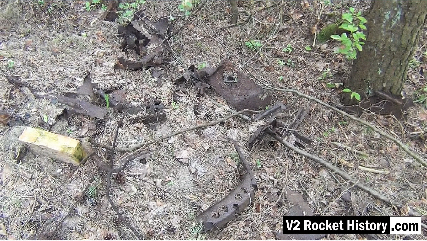
This picture shows a small debris field of steel fragments from the V2 missile 130m South-East of F1, and just 20m to the North East of the foundations of a small heat distribution building. Various body and frame parts can be seen and in the middle foreground a 350mm segment of curved missile body ring is visible. These parts have almost certainly been dug up and exposed by the action of metal detectorists. The metal fragments have been abandoned by their finders as they are perceived to have no financial value and hence are not worth removing from the site.
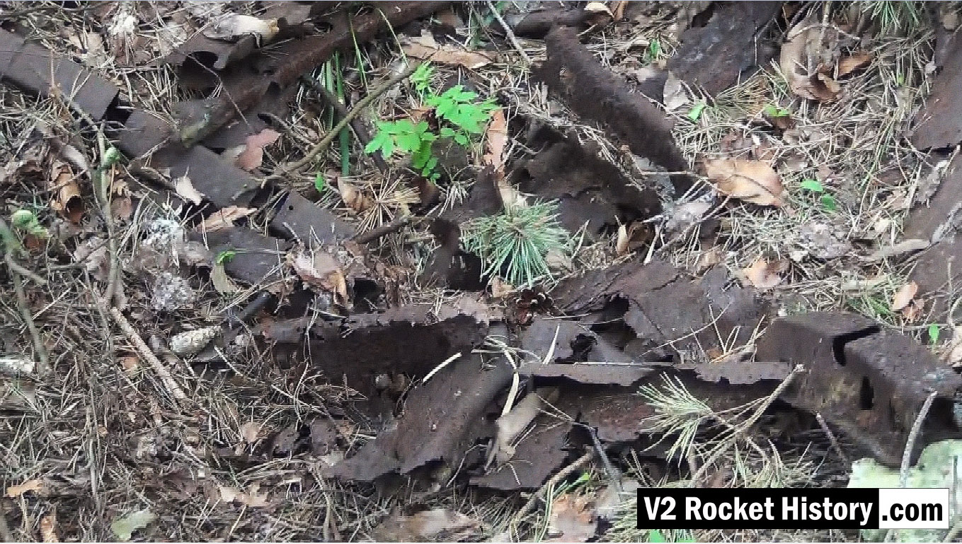
This picture shows a close up detail of parts in a small debris field of steel fragments from the V2 missile 130m South-East of F1, and just 20m to the North East of the foundations of a small heat distribution building. Various body and frame parts can be seen and in the upper left and two segments of curved missile body ring are visible. See previous.
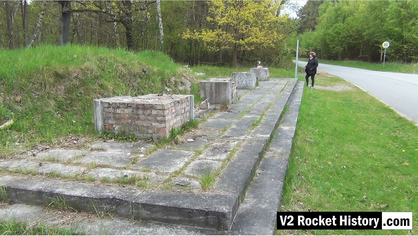
This picture shows the remains of the main South entrance to the Development Works. (also known as Station 7 – Die Hauptwache).
| Album | Development works |
| Category | Peenemünde-Usedom-locations |
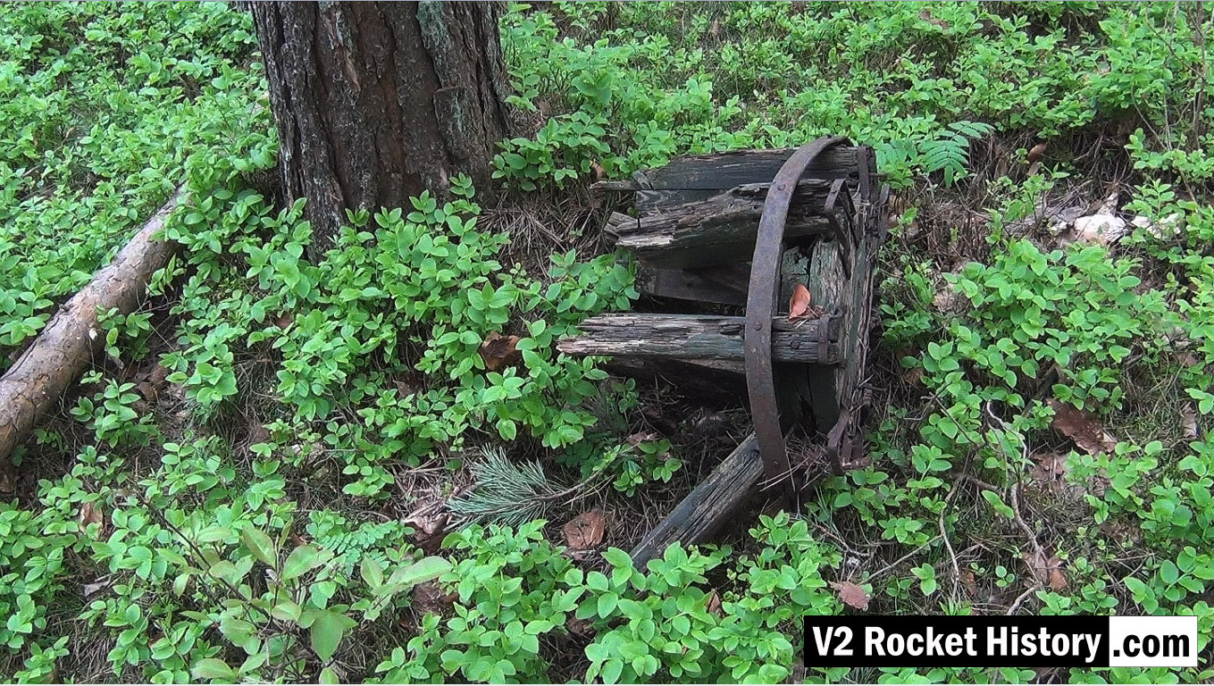
Wooden carboy frame from WW2 (possibly used for transporting small quantities of corrosive and dangerous liquids employed in the V2 steam plant, (such as T-Stoff) laying among trees 190m East of F1 in a location used as an emergency rail freight loading area to F1 due to damage caused by US air raids in August 1944.
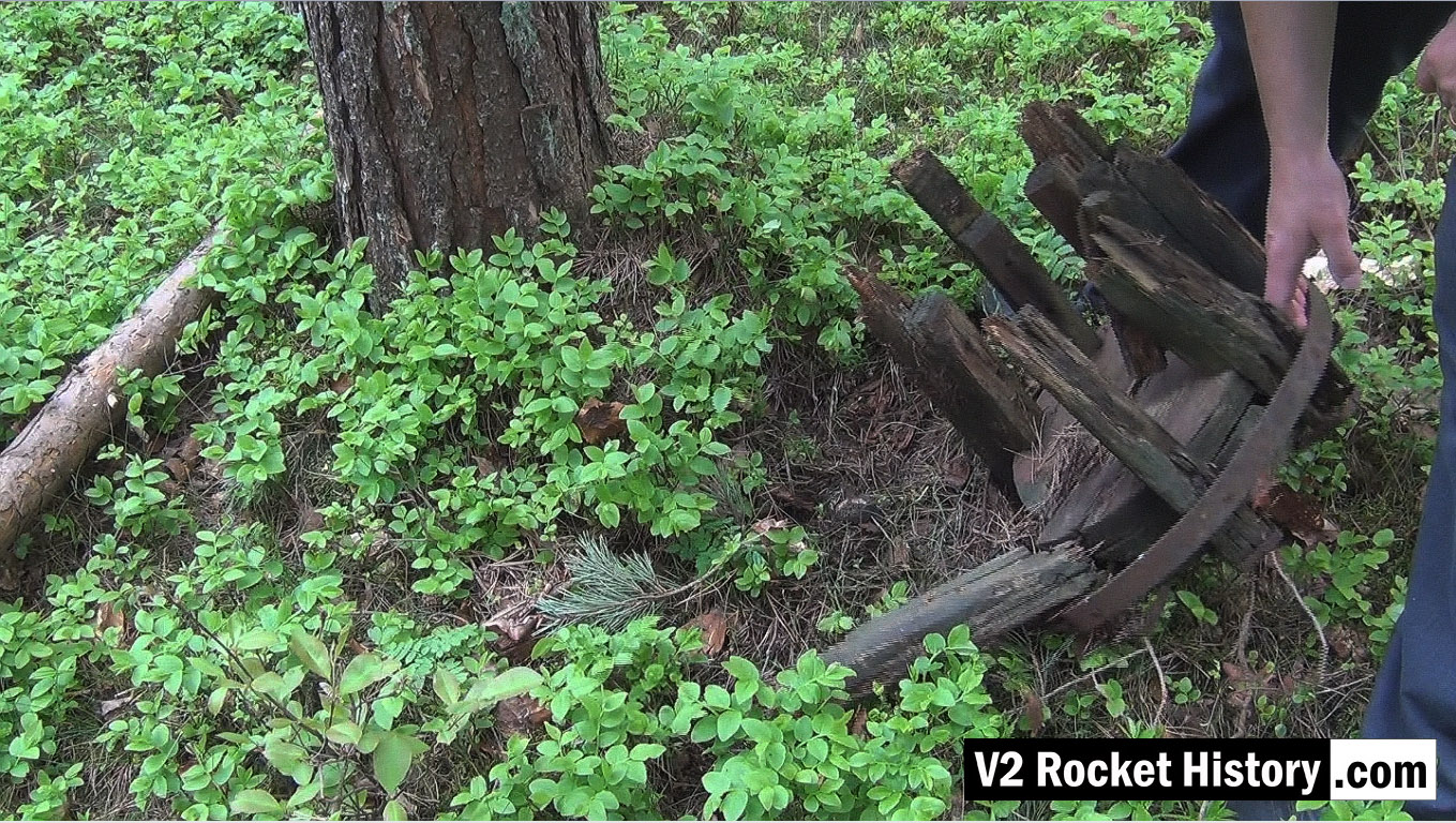
Wooden carboy frame from WW2 (possibly used for transporting small quantities of corrosive and dangerous liquids employed in the V2 steam plant (such a T-Stoff) laying among trees 190m East of F1 in a location used as an emergency rail freight loading area for F1 due to damage caused to rail track by US air raids in August 1944.
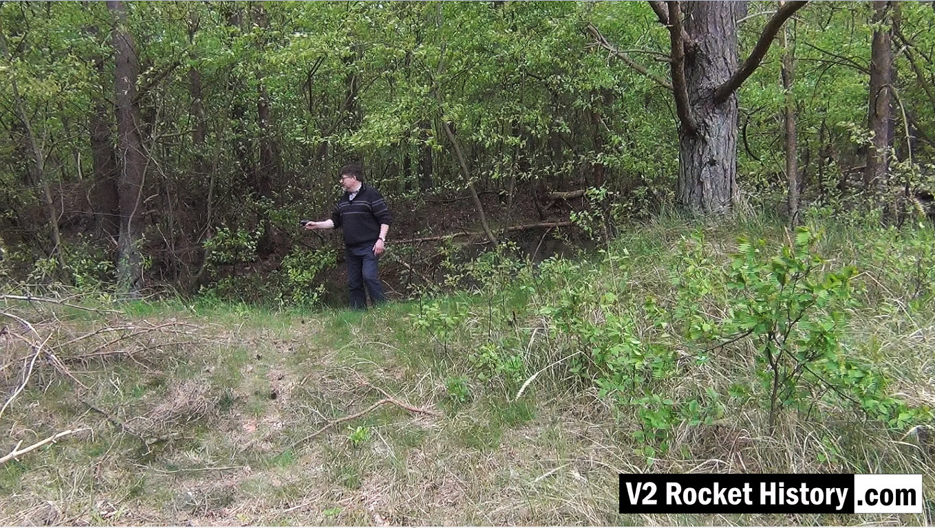
This picture shows Robert Dalby collecting GPS data with a mapping camera just North of the East end of the Admin office rail platform (near the ruins of the small admin/F1 heat distribution hub building). In all of our explorations we routinely collect GPS track and data points to be able to accurately locate finds and establish a precise correlation between areas of interest identified on historical reconnaissance photography and the modern ground terrain. In the picture Robert is pointing a Contour video camera at details of the terrain that automatically captures the camera’s GPS location information. This data can then be combined with satellite imagery, via Google maps, and provide a detailed graphic mapping track alongside the video footage.
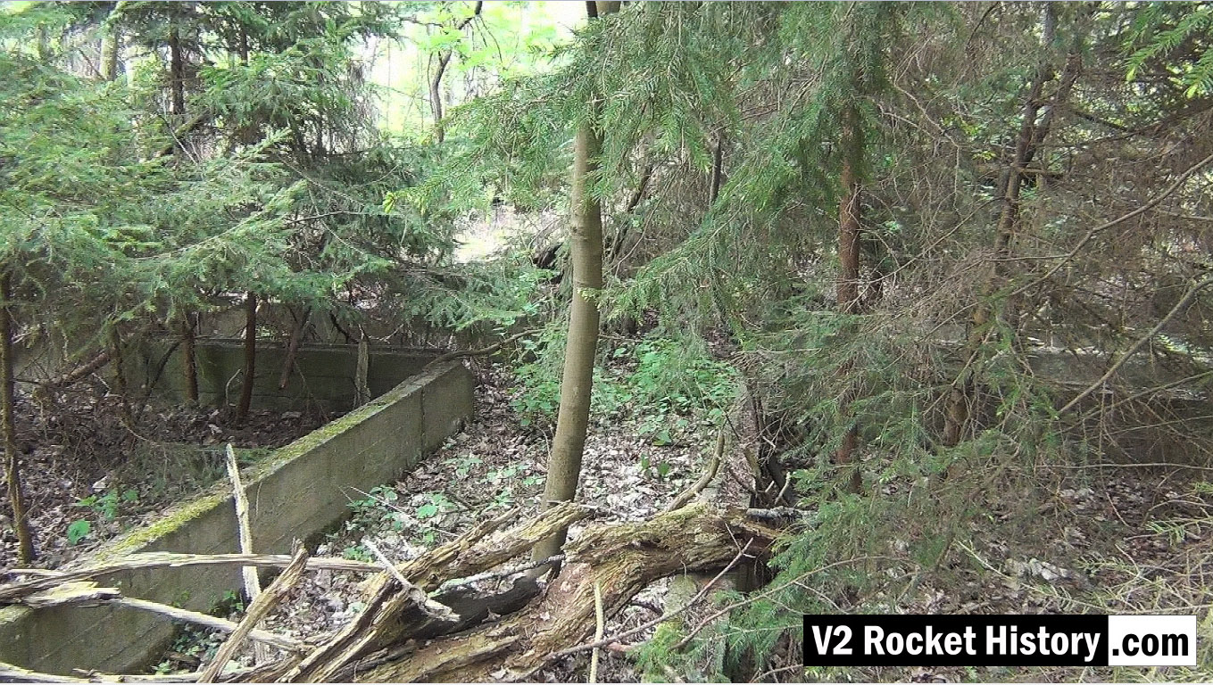
This picture shows some of the extensive ruins that were once part of the railway shed complex West of the railway lines heading to the Development Works. Screen grab from Karlshagen video.
| Album | Karlshagen |
| Category | Peenemünde-Usedom-locations |
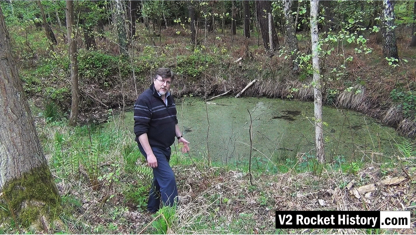
This video still shows Robert in front of a bomb crater on the West or opposite side of the rail lines and road that pass the Repair & Maintenance Hall (R&MH). The crater like so many others, created in a fraction of a second, in August 1944 during a US air raid, has developed in to a thriving eco-system that now teems with all kinds of life. After the passage of more than 70 years the crater is still deep and well defined. There are hundreds of craters like this in the area.
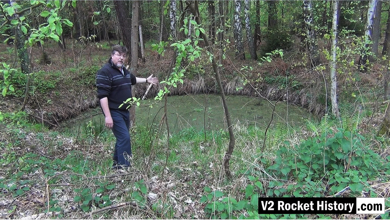
This video still shows the same bomb crater from a slightly different angle. The crater like so many others, created in a fraction of a second in August 1944 during a US air raid, has developed in to a thriving eco-system that now teems with all kinds of life. After the passage of more than 70 years the crater is still deep and well defined. There are hundreds of craters like this in the area.
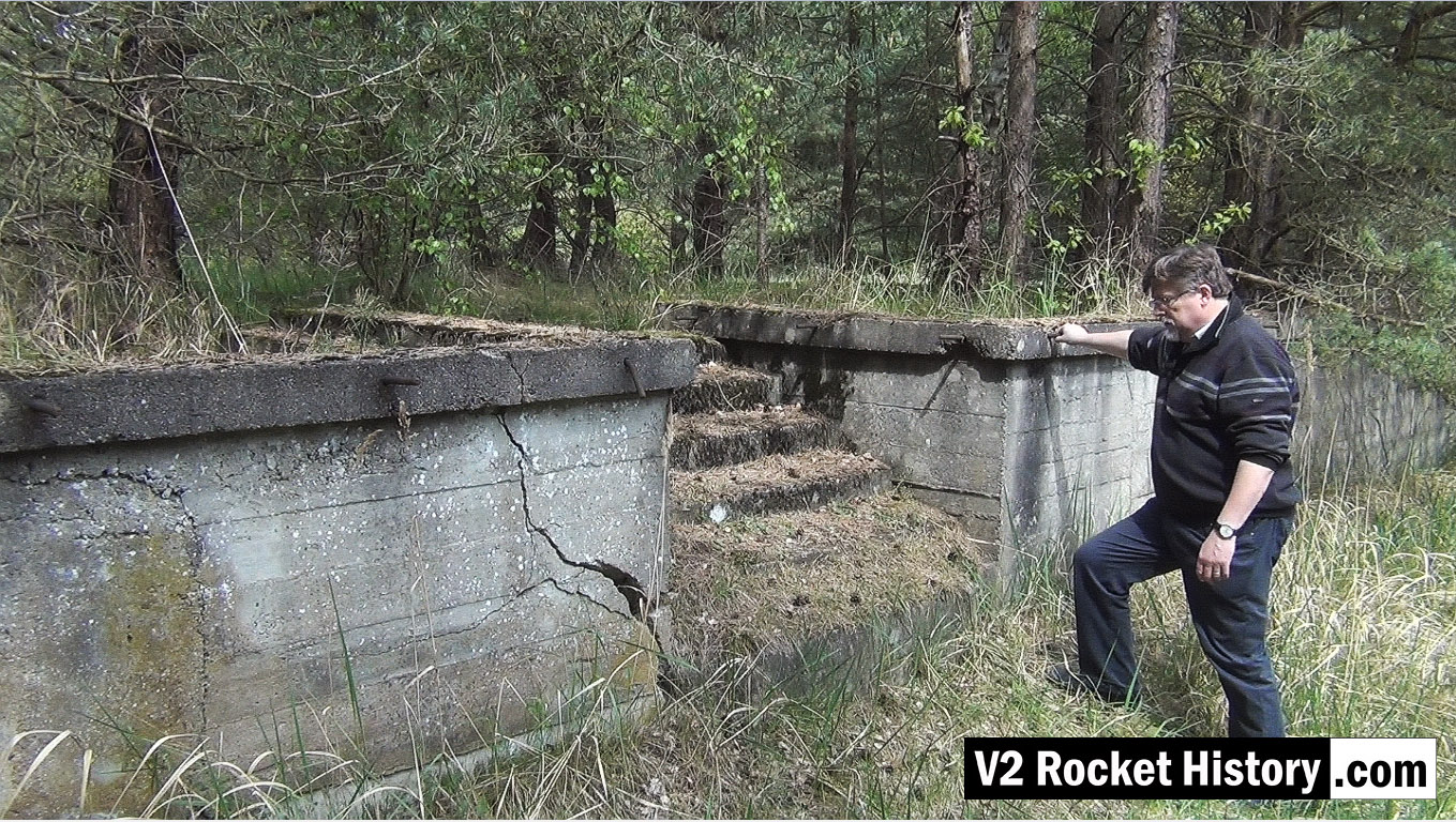
This video screen grab shows Robert about to climb the steps up onto the rail and road loading station 9 (also called Die Verladerampen or in English, The loading ramps). This storage and loading facility was never finished during the war and was intended to be a more elaborate with large storage buildings – but the pressure of war and constant use of the area prevented further development. The area is still surprisingly intact today with a strong correspondence between modern ground detail and historical reconnaissance photography.

Testing fuel injectors
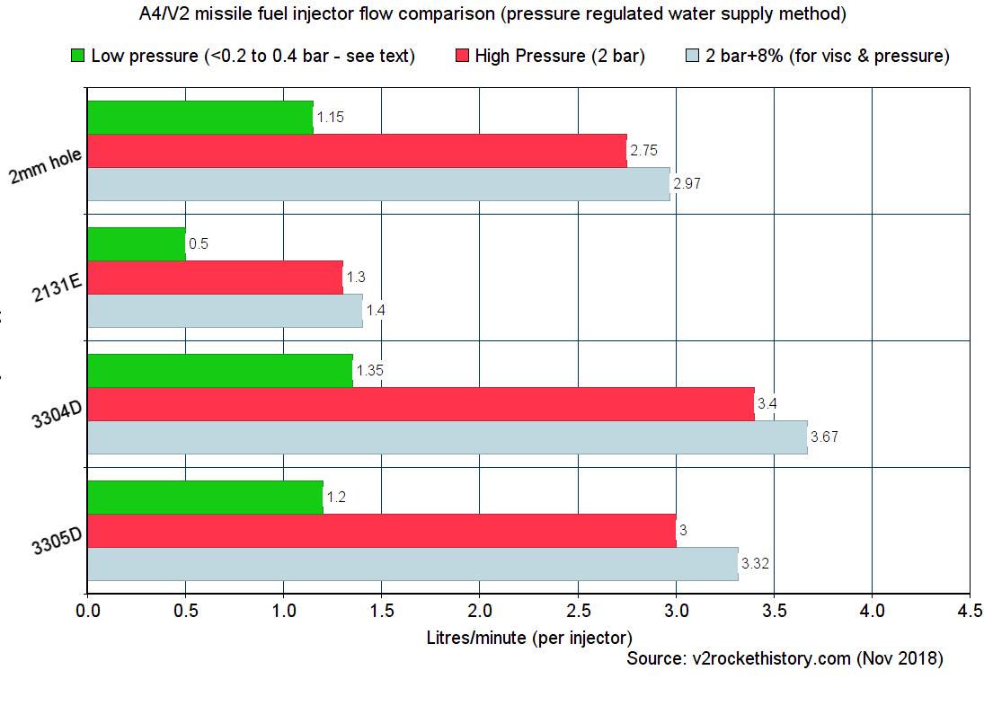
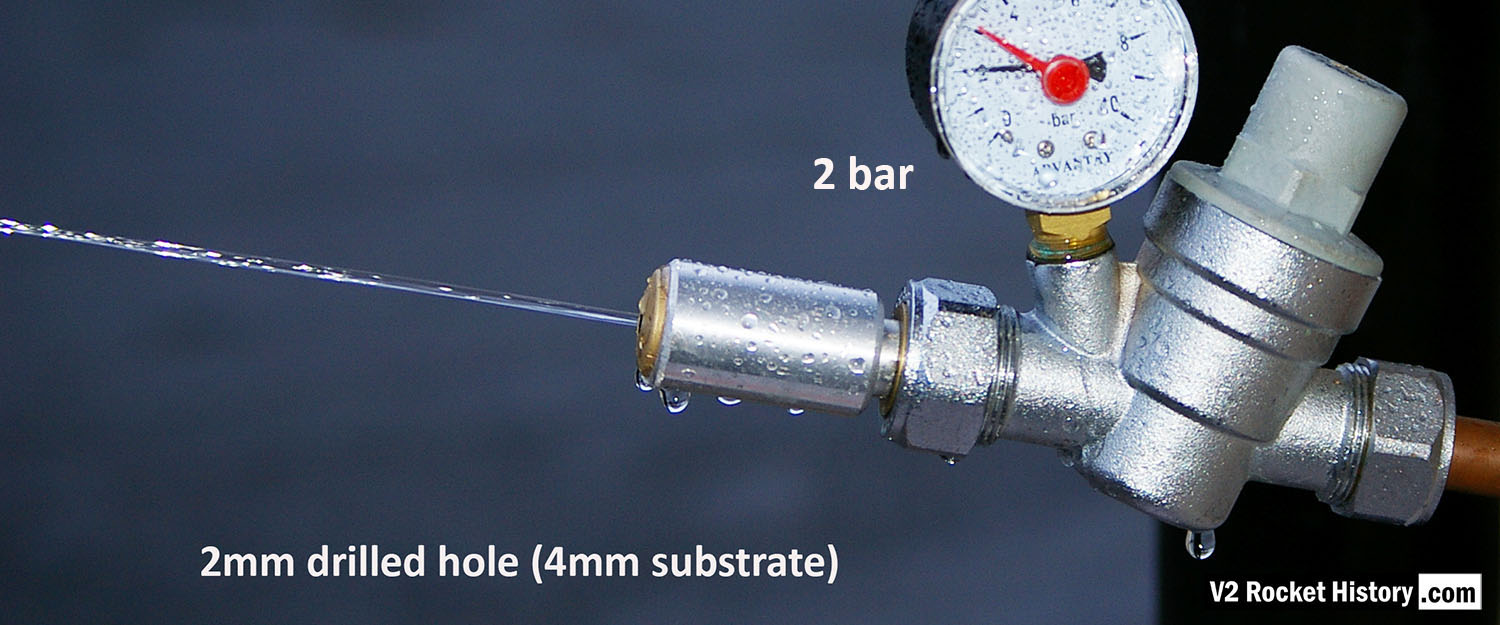
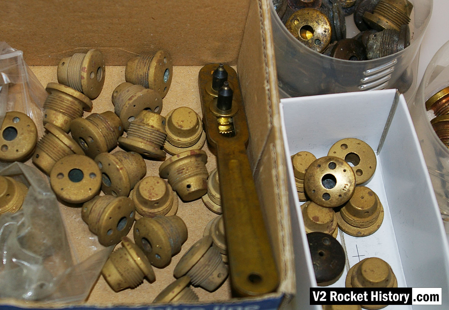
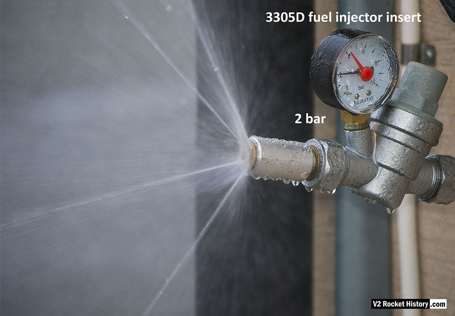
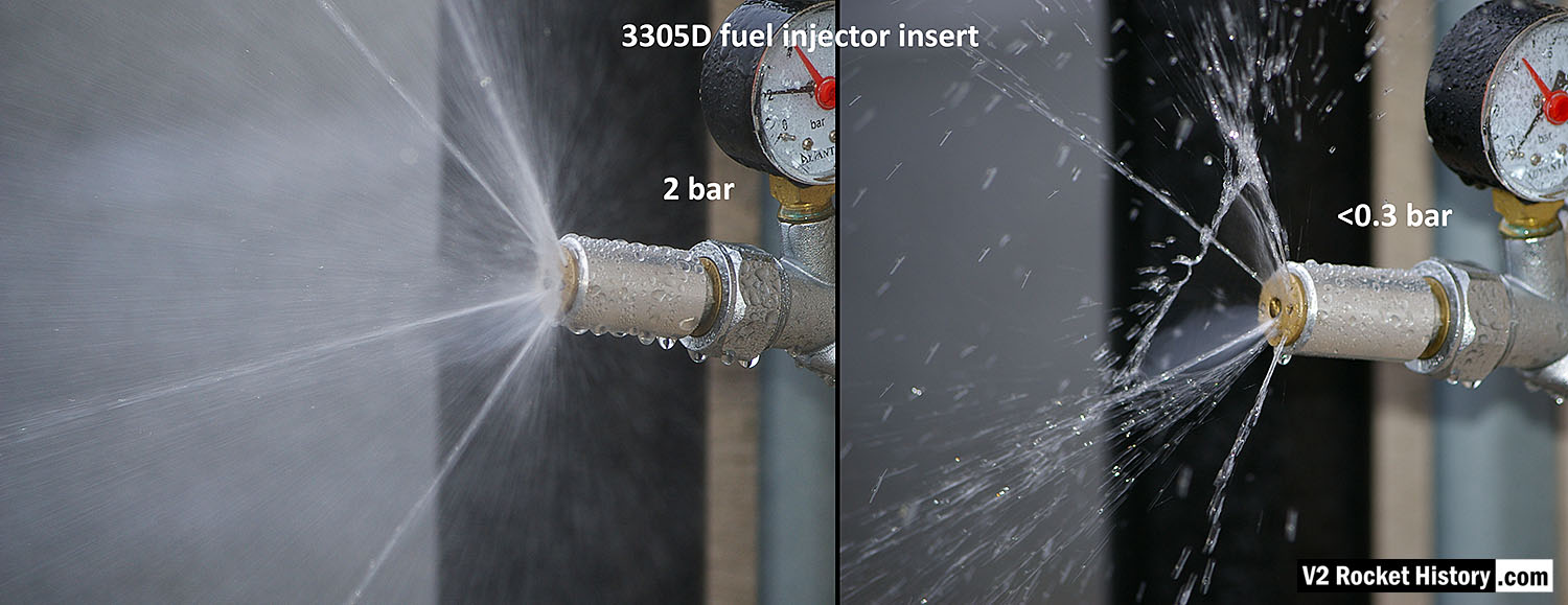
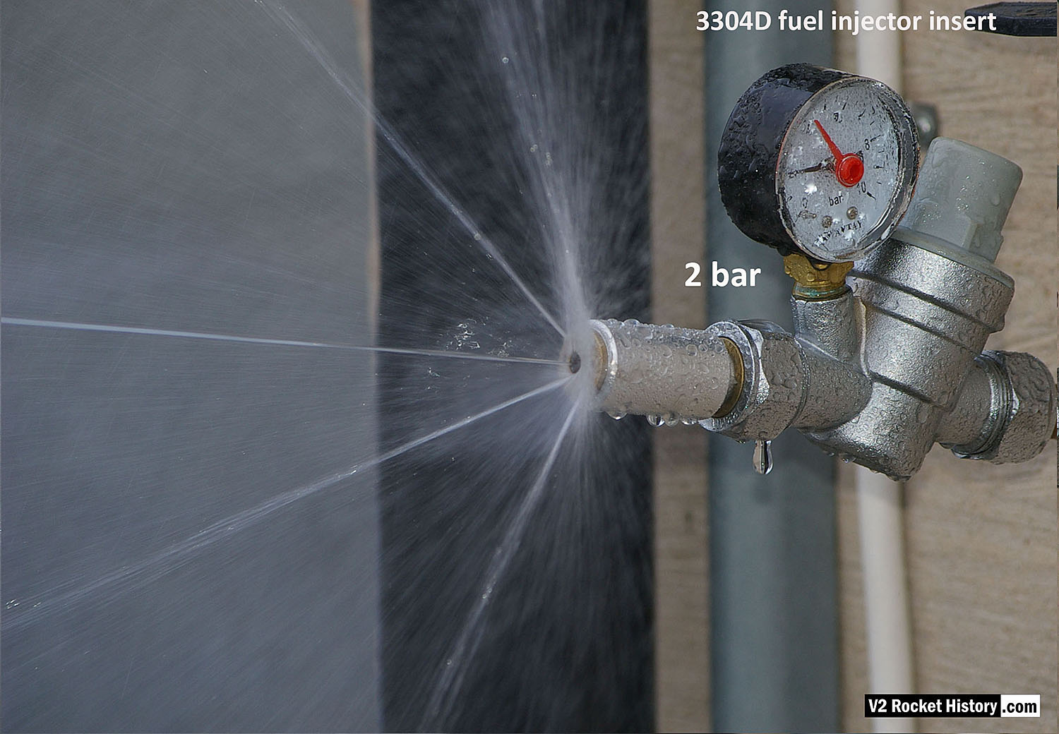
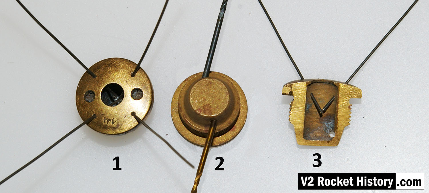
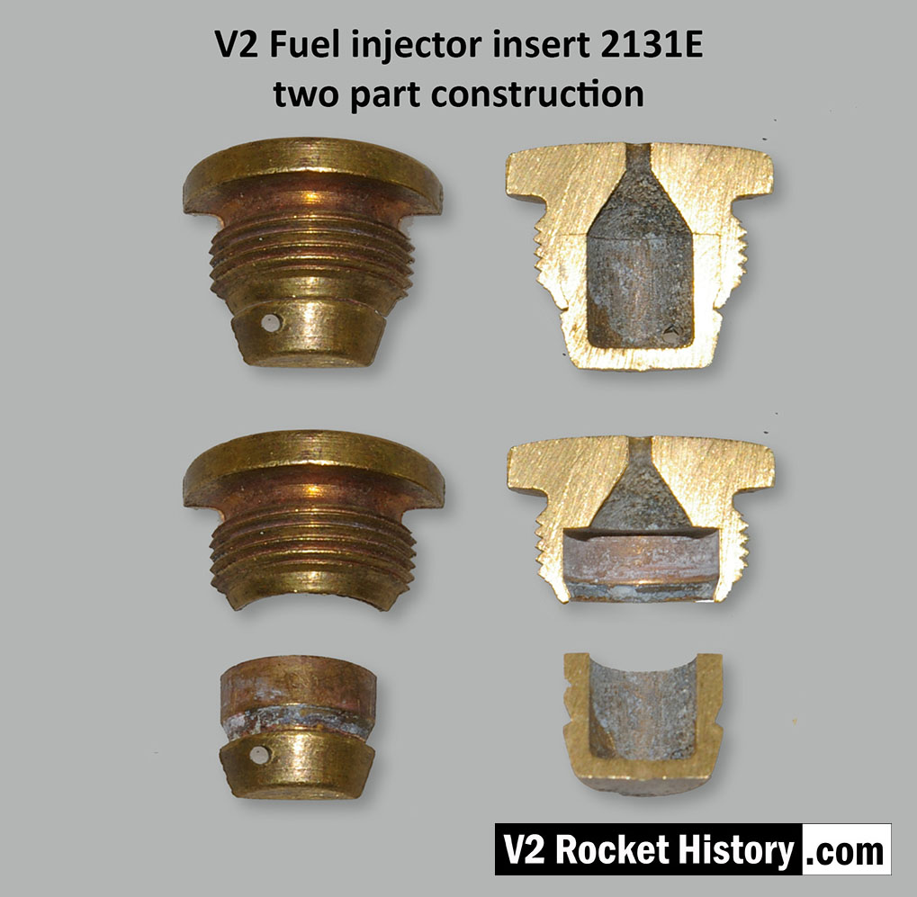
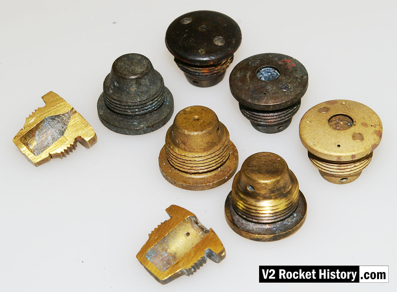
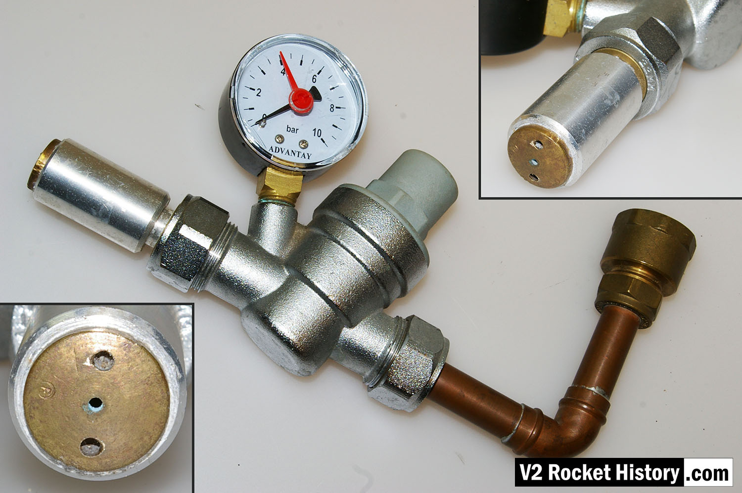

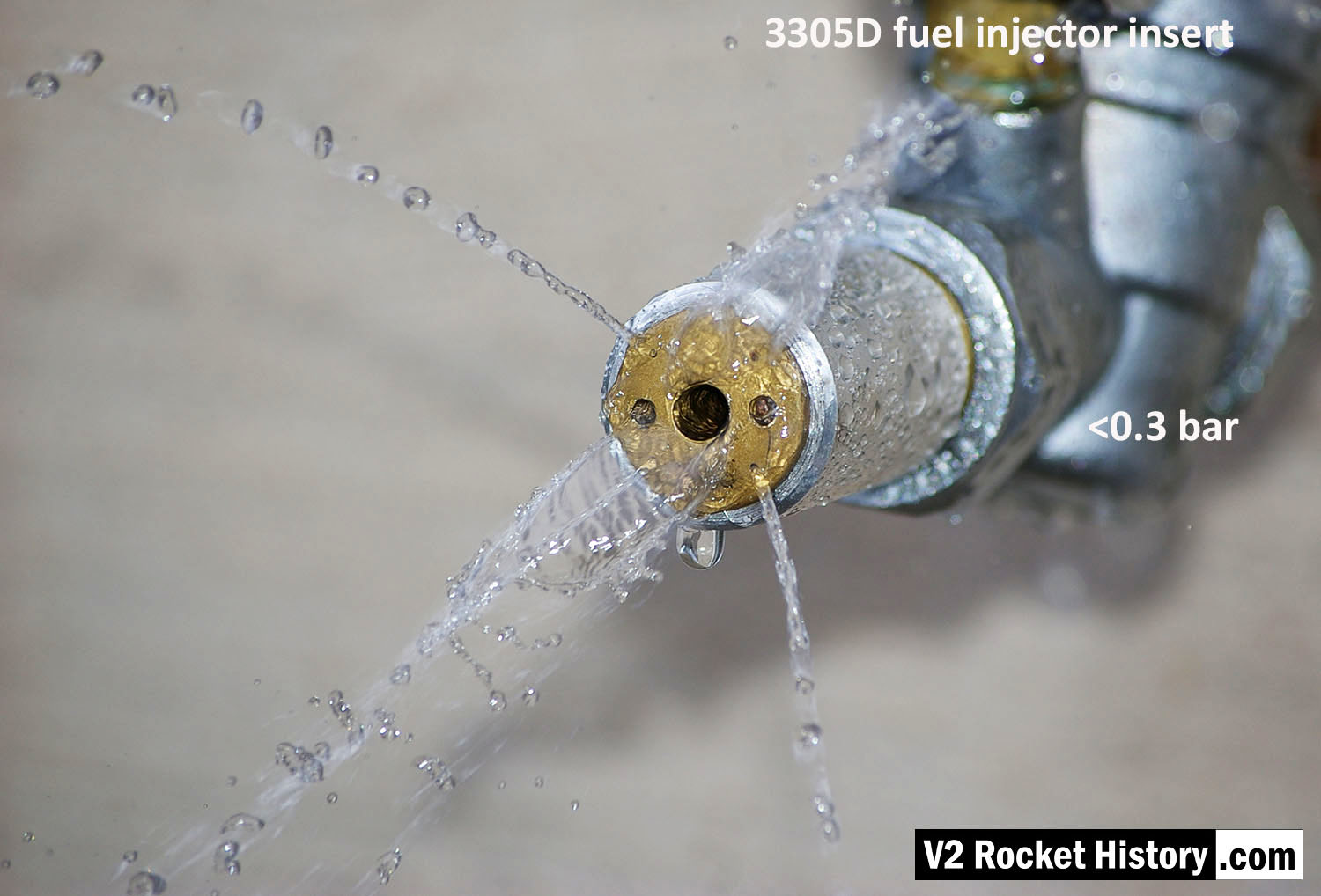
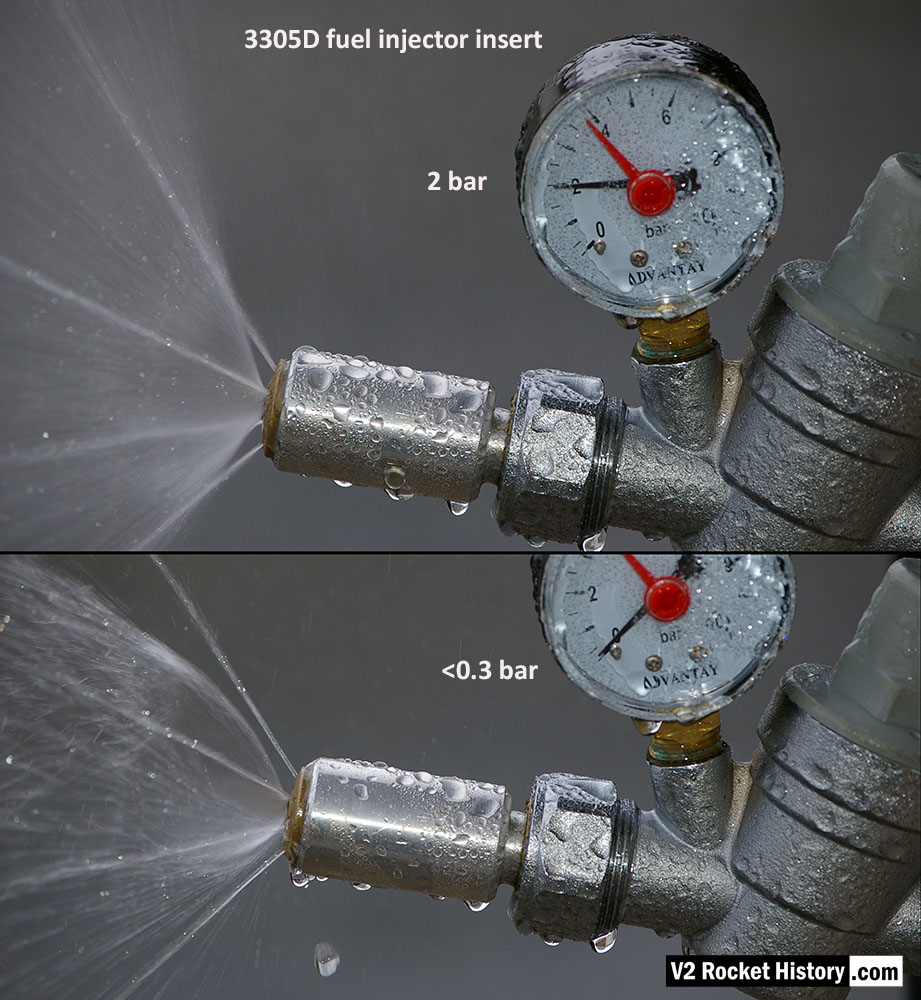
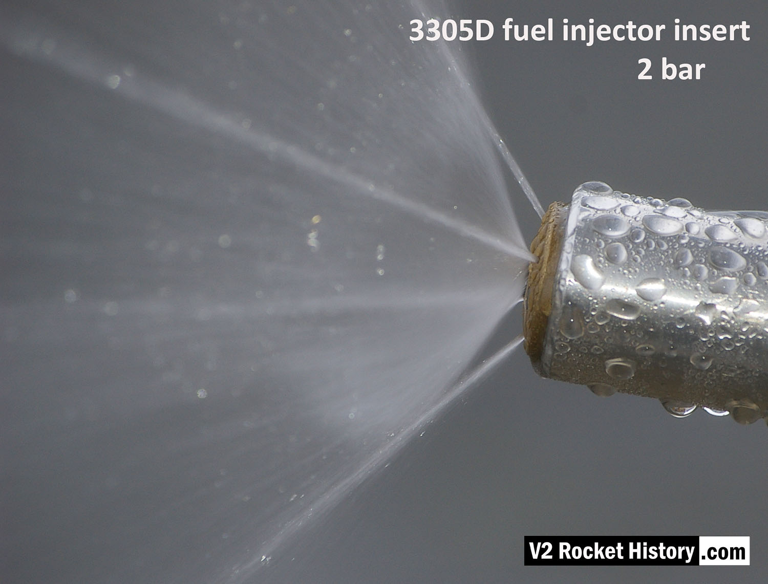
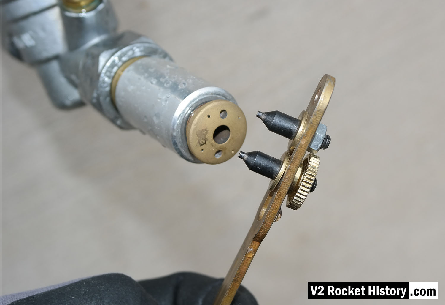
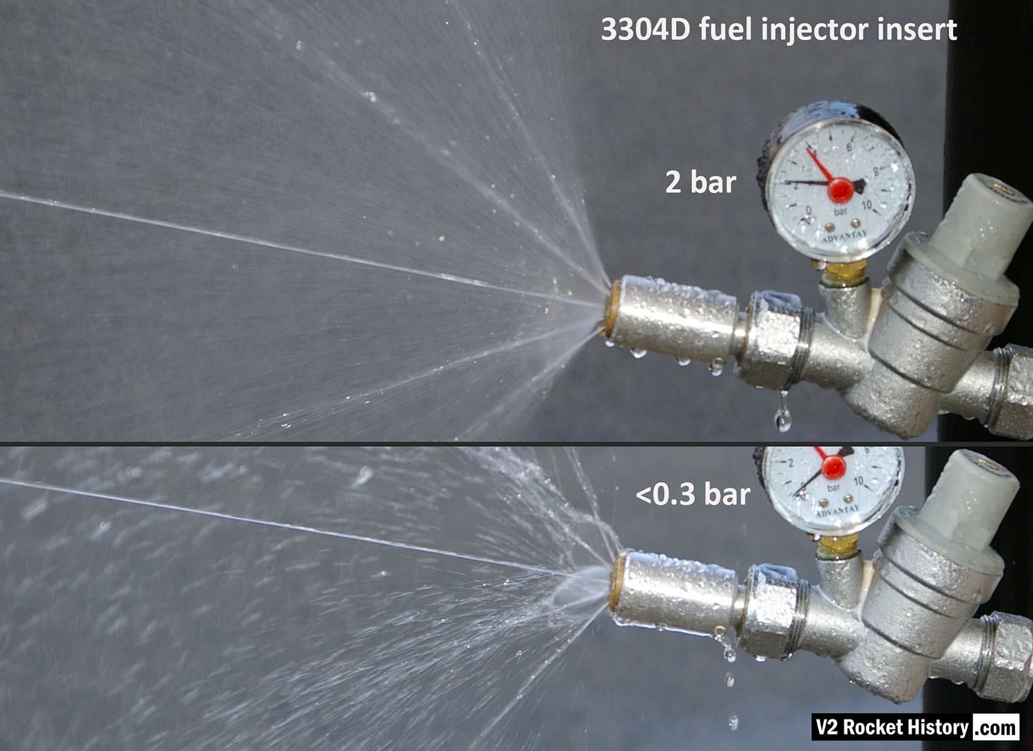
The chart shows water delivery in litres per minute per injector

