

Archives: Gmedia Albums
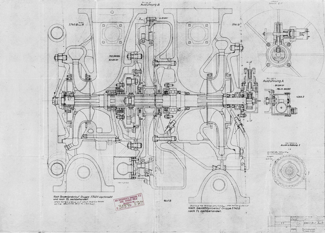
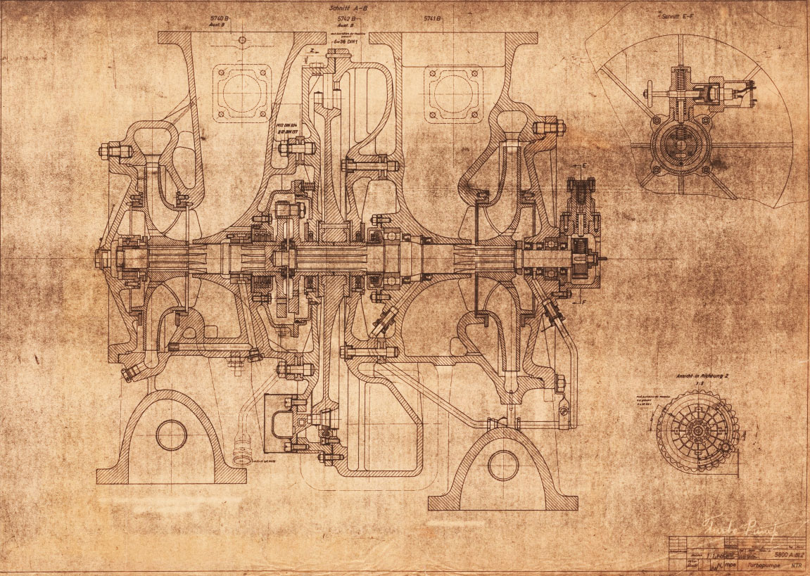
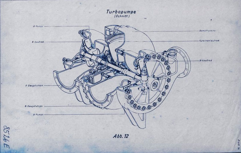
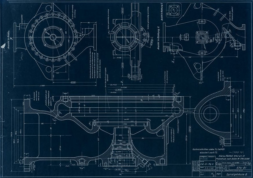
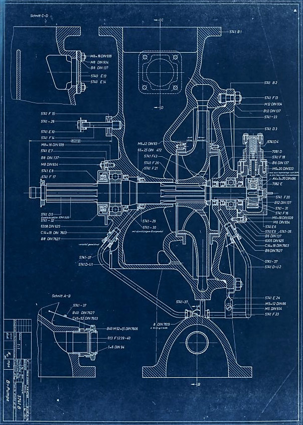
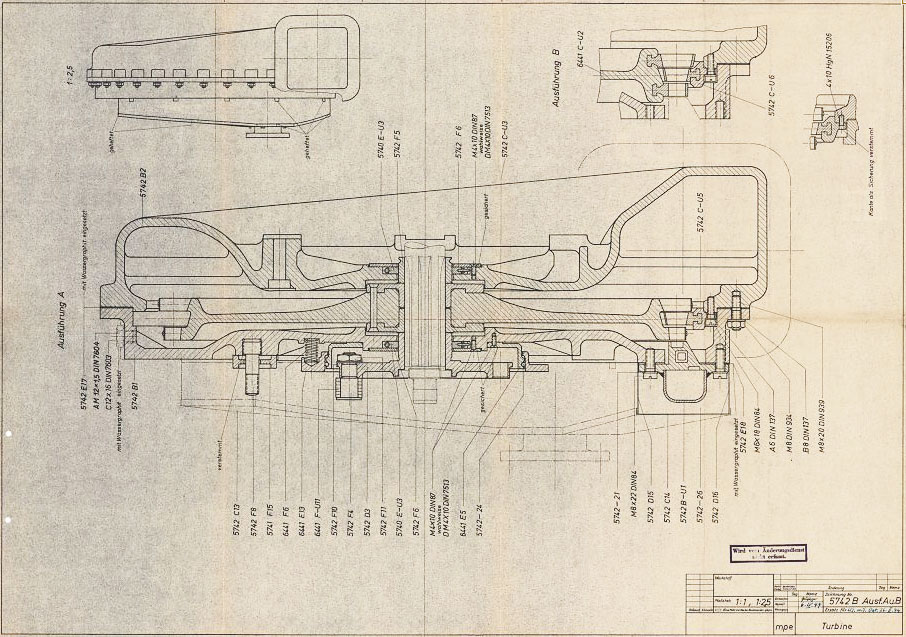
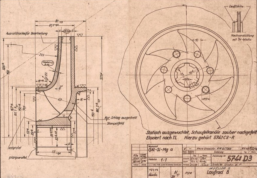


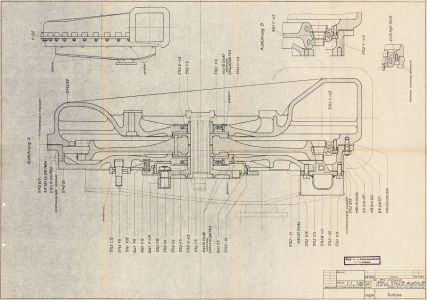

Turbopump 3D CAD
3D CAD model images of the A4/V2 rocket engine’s steam turbine powered propellent pumps – all images by Ray Matter. To see Ray Matter’s blog 3D CAD modelling the V2 rocket turbopump introducing these images, just click the link.
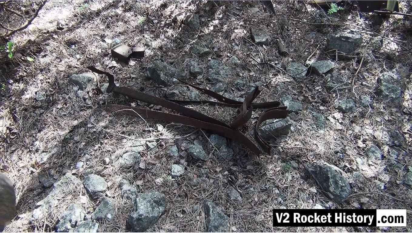
V2 fin relic near F1
V2 fin relic near F1
Picture shows parts of V2 missile fin structure laying on open ground near area between admin offices and F1 (near Admin. block railway platform, see map).
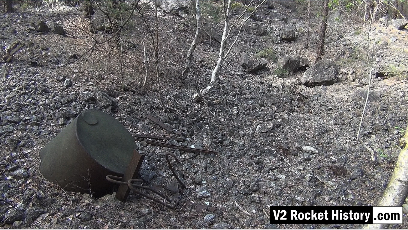
Storage vessel within F1 boundary
Storage vessel within F1 boundary
Picture shows metal debris within the F1 factory boundary walls. The purpose of the part buried liquid storage vessel in the foreground is unknown but it is not a vessel capable of being pressurised. Other assorted metal debris include pipe and cable wall cleats, as well as steel armature rods from reinforced concrete castings (powerful demolition explosions have freed the steel rods from the concrete). These reinforcement rods are a common sight in the environs of Fertigungshalle Eins (F1) and the nearby Repair & Maintenance Hall (R&MH).
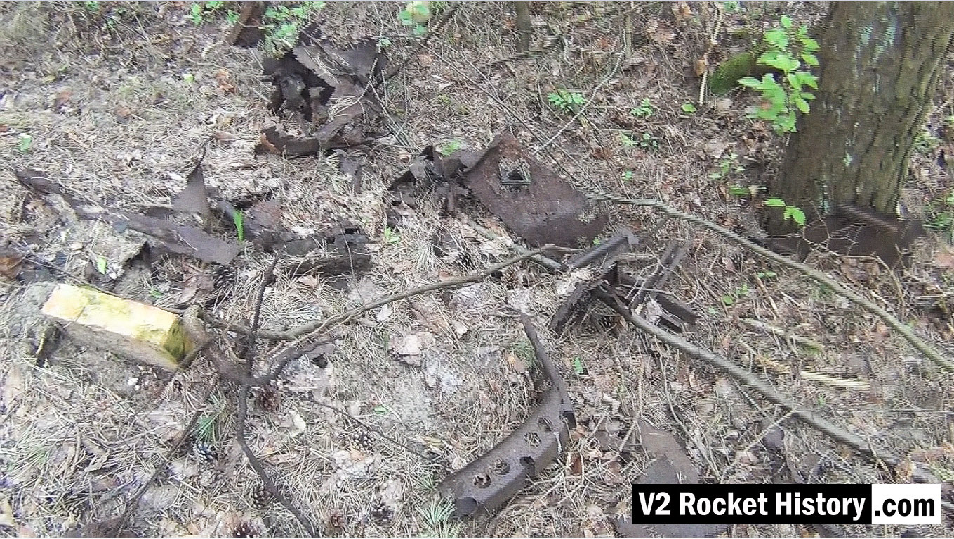
V2 missile debris field SE of F1
V2 missile debris field SE of F1
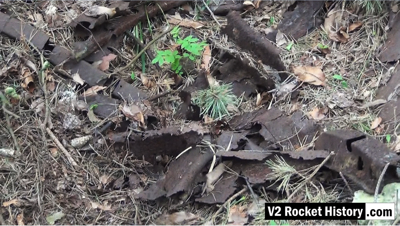
This picture shows a small debris field of steel fragments from the V2 missile 130m South-East of F1, and just 20m to the North East of the foundations of a small heat distribution building. Various body and frame parts can be seen and in the middle foreground a 350mm segment of curved missile body ring is visible. These parts have almost certainly been dug up and exposed by the action of metal detectorists. The metal fragments have been abandoned by their finders as they are perceived to have no financial value and hence are not worth removing from the site.
V2 missile debris near F1
V2 missile debris near F1
This picture shows a close up detail of parts in a small debris field of steel fragments from the V2 missile 130m South-East of F1, and just 20m to the North East of the foundations of a small heat distribution building. Various body and frame parts can be seen and in the upper left and two segments of curved missile body ring are visible. See previous.
Remains of main entrance guard house
Remains of main entrance guard house
This picture shows the remains of the main South entrance to the Development Works. (also known as Station 7 – Die Hauptwache).
| Album | Development works |
| Category | Peenemünde-Usedom-locations |
Wooden Carboy frame
Wooden Carboy frame
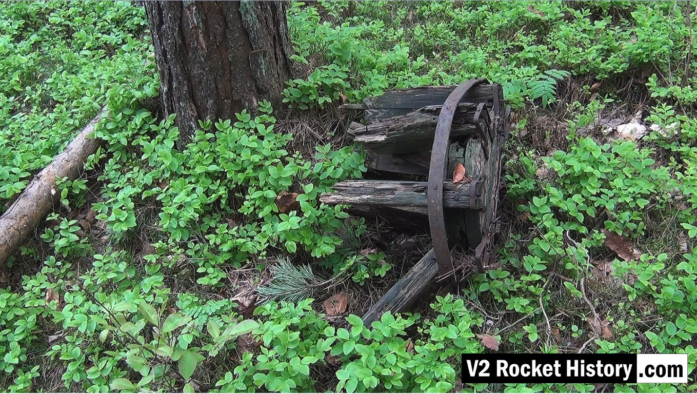
Wooden carboy frame from WW2 (possibly used for transporting small quantities of corrosive and dangerous liquids employed in the V2 steam plant, (such as T-Stoff) laying among trees 190m East of F1 in a location used as an emergency rail freight loading area to F1 due to damage caused by US air raids in August 1944.
Wooden carboy frame examined
Wooden carboy frame examined
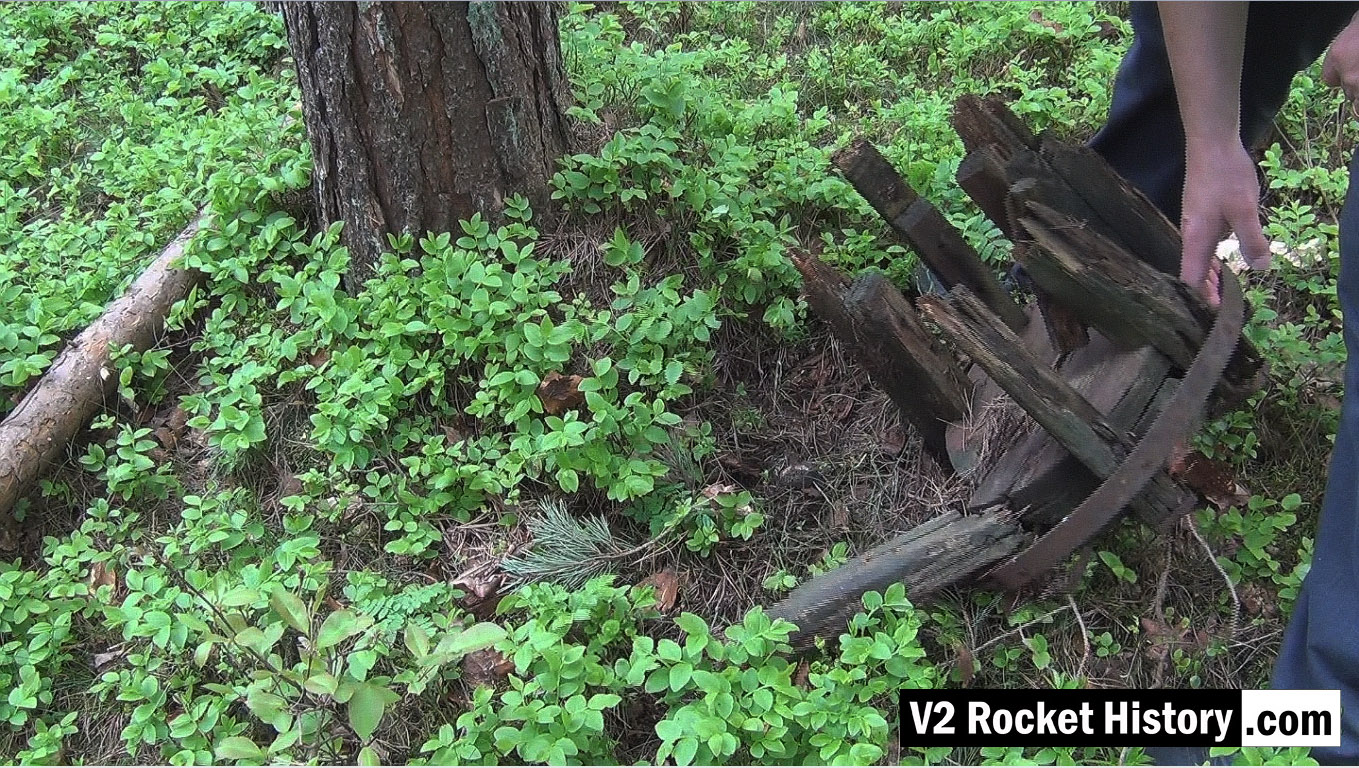
Wooden carboy frame from WW2 (possibly used for transporting small quantities of corrosive and dangerous liquids employed in the V2 steam plant (such a T-Stoff) laying among trees 190m East of F1 in a location used as an emergency rail freight loading area for F1 due to damage caused to rail track by US air raids in August 1944.
Collecting GPS data near F1
Collecting GPS data near F1
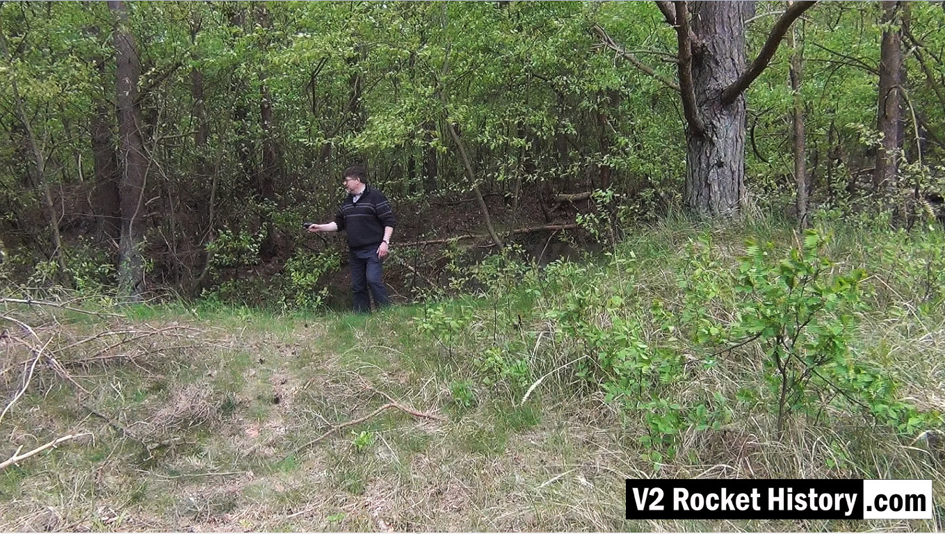
This picture shows Robert Dalby collecting GPS data with a mapping camera just North of the East end of the Admin office rail platform (near the ruins of the small admin/F1 heat distribution hub building). In all of our explorations we routinely collect GPS track and data points to be able to accurately locate finds and establish a precise correlation between areas of interest identified on historical reconnaissance photography and the modern ground terrain. In the picture Robert is pointing a Contour video camera at details of the terrain that automatically captures the camera’s GPS location information. This data can then be combined with satellite imagery, via Google maps, and provide a detailed graphic mapping track alongside the video footage.
Karlshagen West, railway sheds ruins
Karlshagen West, railway sheds ruins
This picture shows some of the extensive ruins that were once part of the railway shed complex West of the railway lines heading to the Development Works. Screen grab from Karlshagen video.
| Album | Karlshagen |
| Category | Peenemünde-Usedom-locations |
1944 bomb crater near R&MH
1944 bomb crater near R&MH
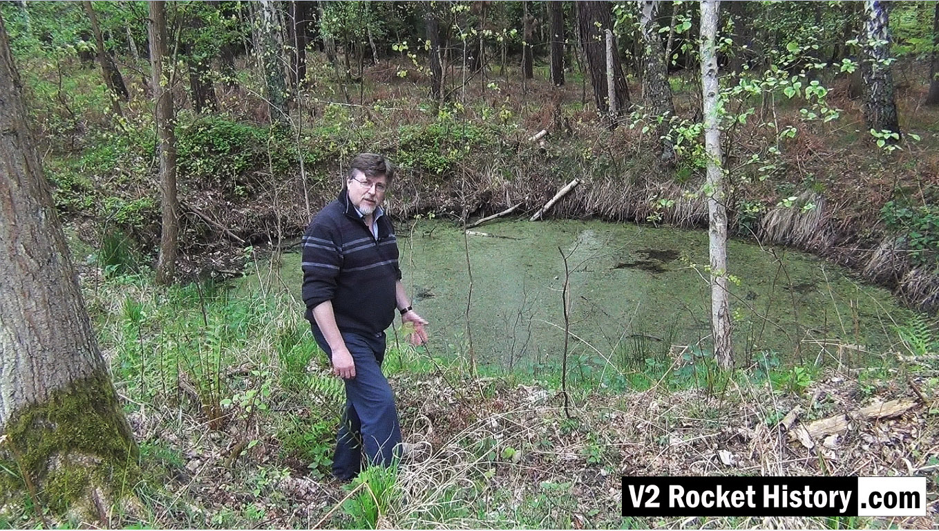
This video still shows Robert in front of a bomb crater on the West or opposite side of the rail lines and road that pass the Repair & Maintenance Hall (R&MH). The crater like so many others, created in a fraction of a second, in August 1944 during a US air raid, has developed in to a thriving eco-system that now teems with all kinds of life. After the passage of more than 70 years the crater is still deep and well defined. There are hundreds of craters like this in the area.
1944 bomb near R&MH – 2nd view
1944 bomb near R&MH – 2nd view
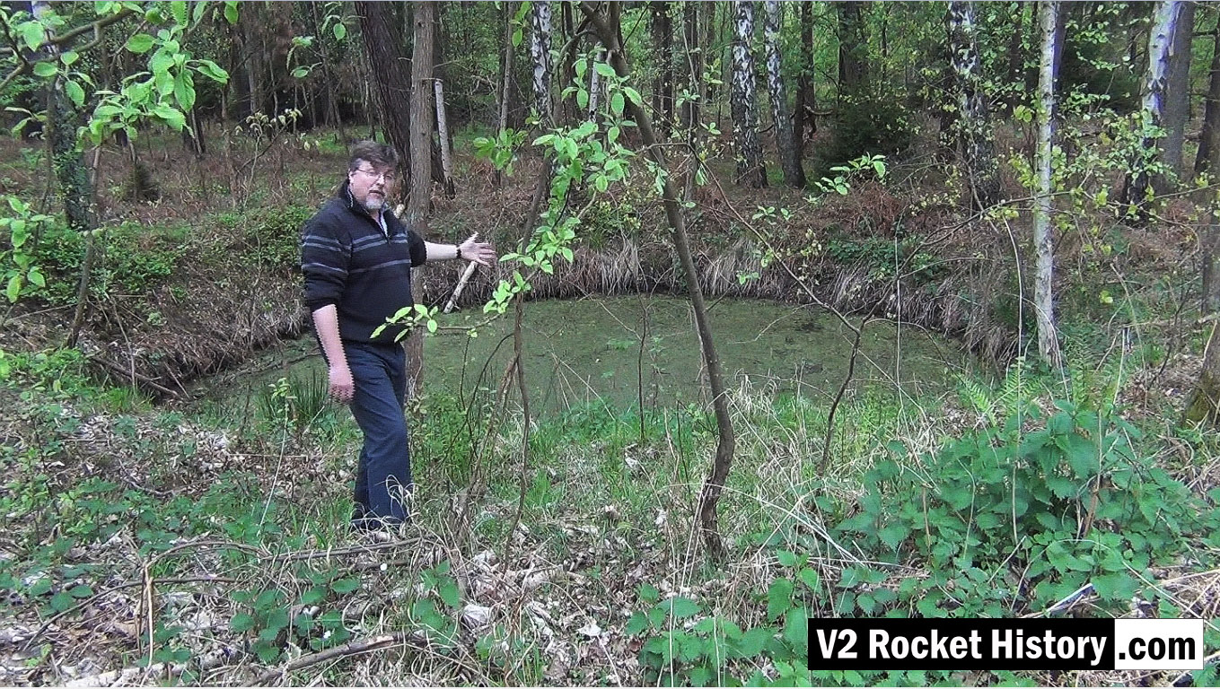
This video still shows the same bomb crater from a slightly different angle. The crater like so many others, created in a fraction of a second in August 1944 during a US air raid, has developed in to a thriving eco-system that now teems with all kinds of life. After the passage of more than 70 years the crater is still deep and well defined. There are hundreds of craters like this in the area.
Ruins of materials storage station No 9 next to F1
Ruins of materials storage station No 9 next to F1
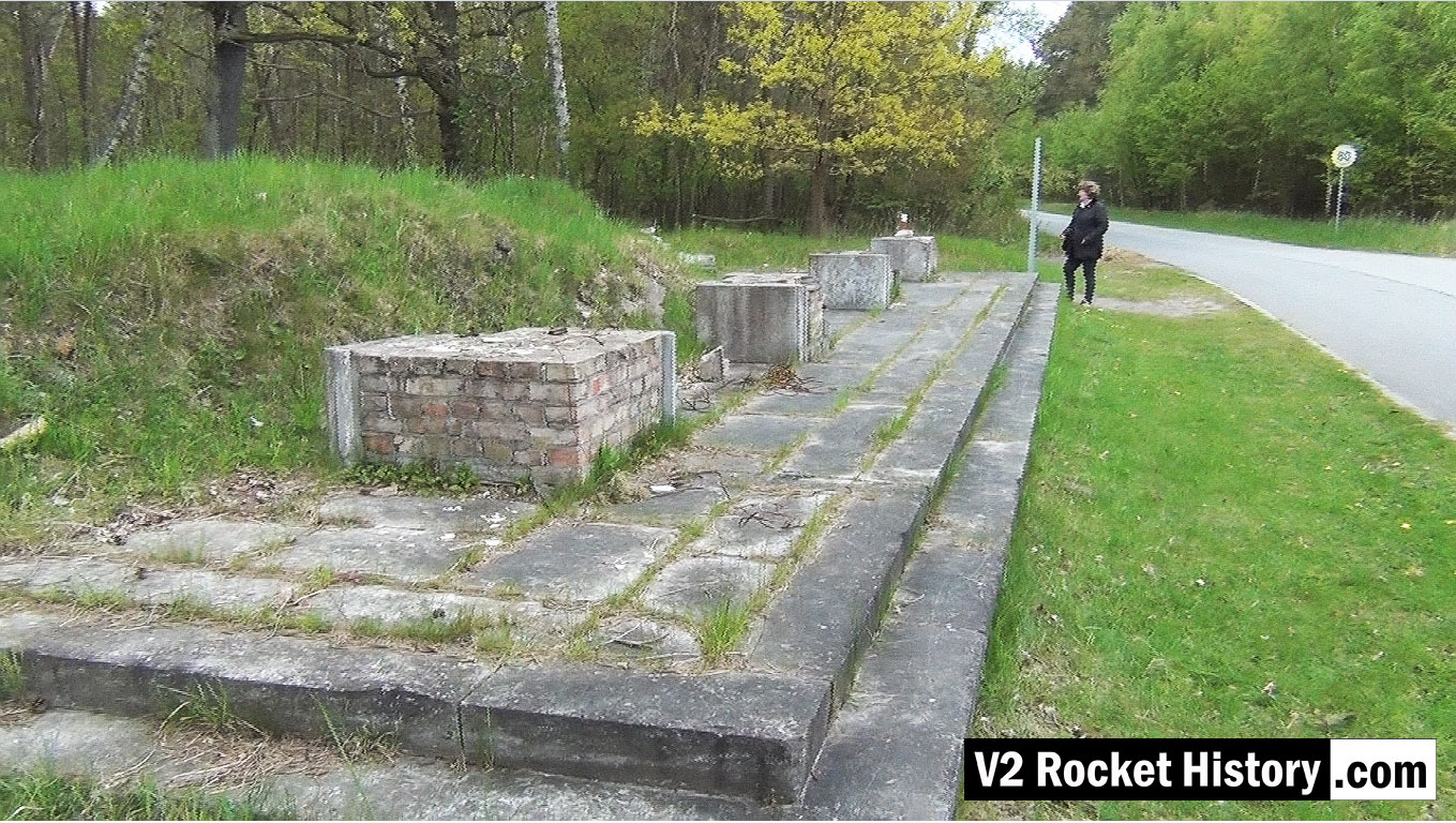
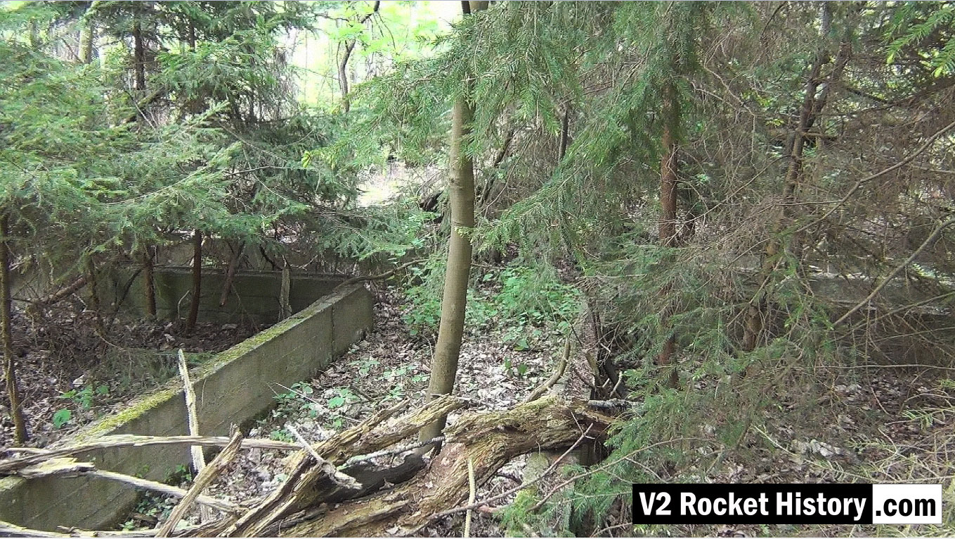
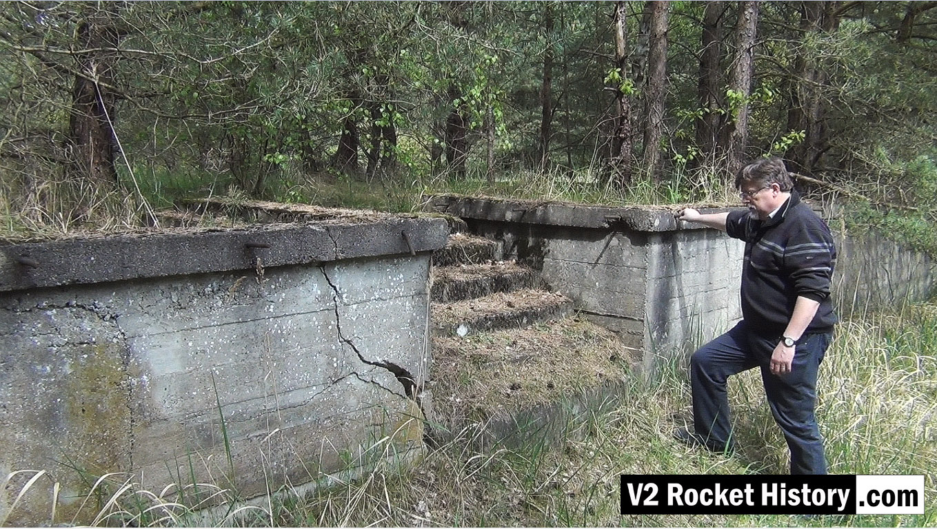
This video screen grab shows Robert about to climb the steps up onto the rail and road loading station 9 (also called Die Verladerampen or in English, The loading ramps). This storage and loading facility was never finished during the war and was intended to be a more elaborate with large storage buildings – but the pressure of war and constant use of the area prevented further development. The area is still surprisingly intact today with a strong correspondence between modern ground detail and historical reconnaissance photography.
Valves
Images of the main valves involved in the propellant flow of the A4 / V2 liquid fuelled rocket engine

Valves
Images of the main valves involved in the propellant flow of the A4 / V2 liquid fuelled rocket engine


Description
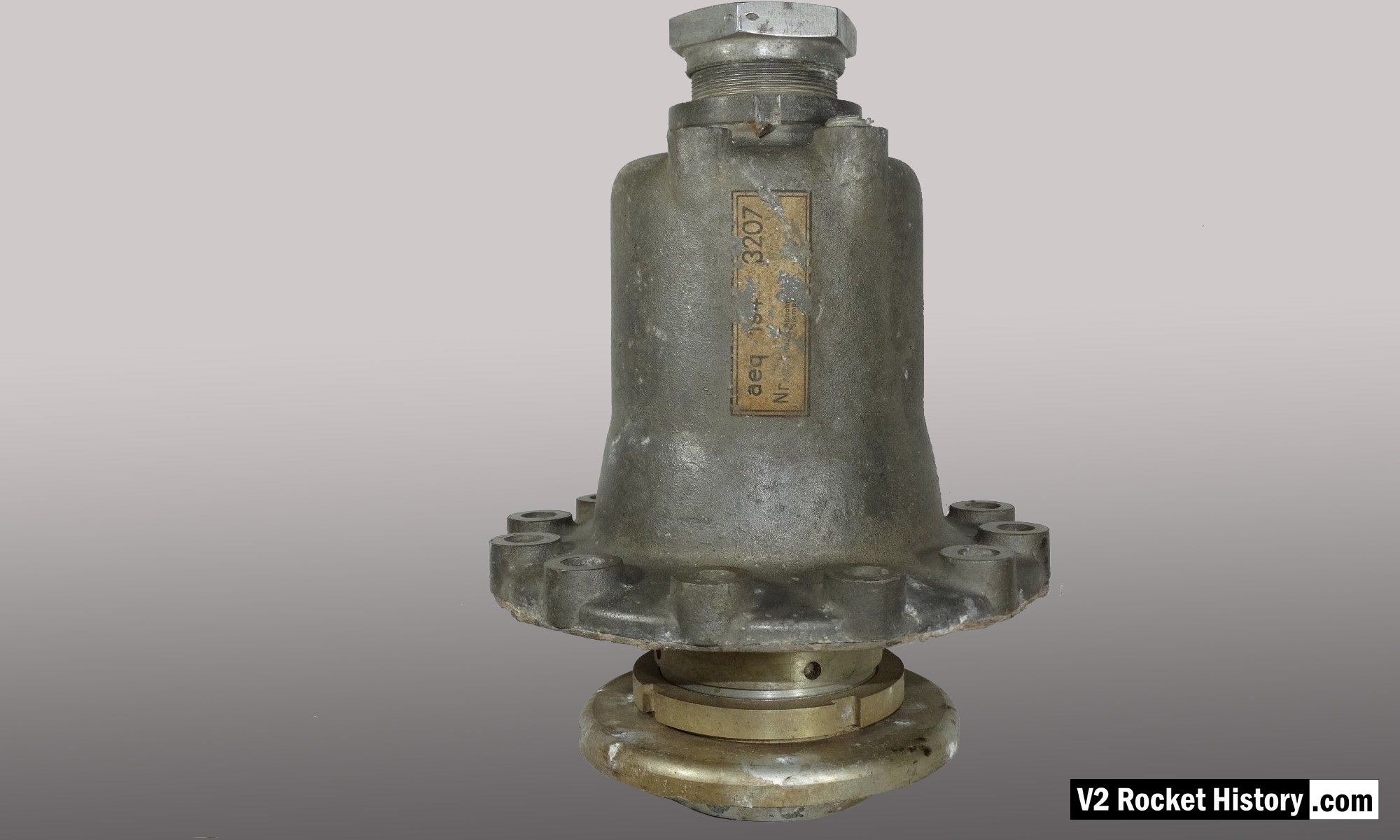
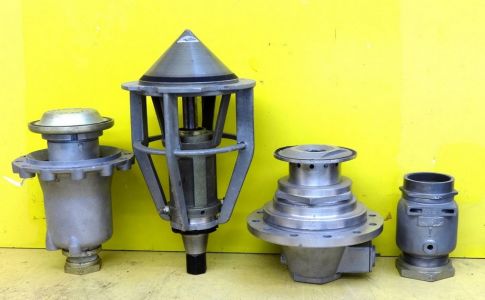
Relic of main alcohol valve with manufacturer code aeq (aeq = Bartoc & Co., Maschinenfabrik u. Giesserei Hedwikow,bei Caslau (Caslav) Czech Republic). An air (nitrogen) inlet pressure of 440 to 530 psi (30 to 36 Bar) was required to close this valve against its internal spring and the force of the turbo-pump. The large nut at the top is the connection for the fuel return (or ‘revolving’line) pipe, and the air and electrical input ports can be seen to the right (air), and left (elec.) just below this point. V2RH image
Location
Anatomy of the V2: 18-pot injector head
18-pot Upper Veil Manifold detail
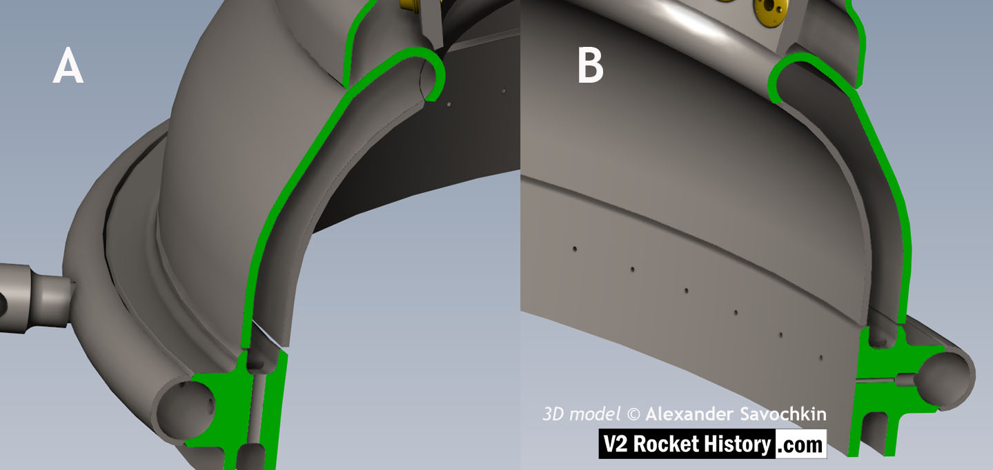
18-pot Upper Veil Manifold detail
Close-up detail showing independent pathway for fuel passing into injector head and fuel passed down from the head to be used for veil cooling system. Fig. A shows vertical passages for overall fuel feed to the head and Fig.B shows horizontal pathway for veil coolant fed from the head via the veil coolant distributor ring or manifold. 3D model by Alexander Savochkin
V2 rocket 18-pot Head: Top
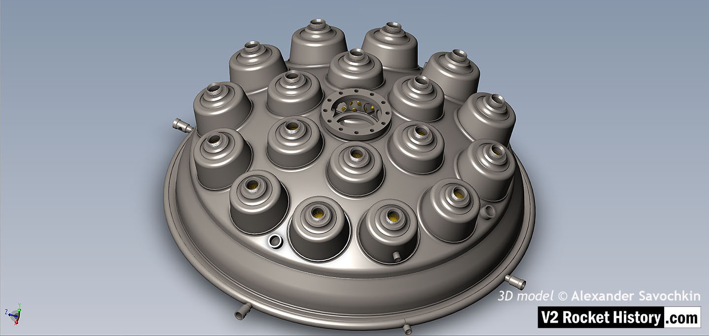
V2 rocket 18-pot Head: Top
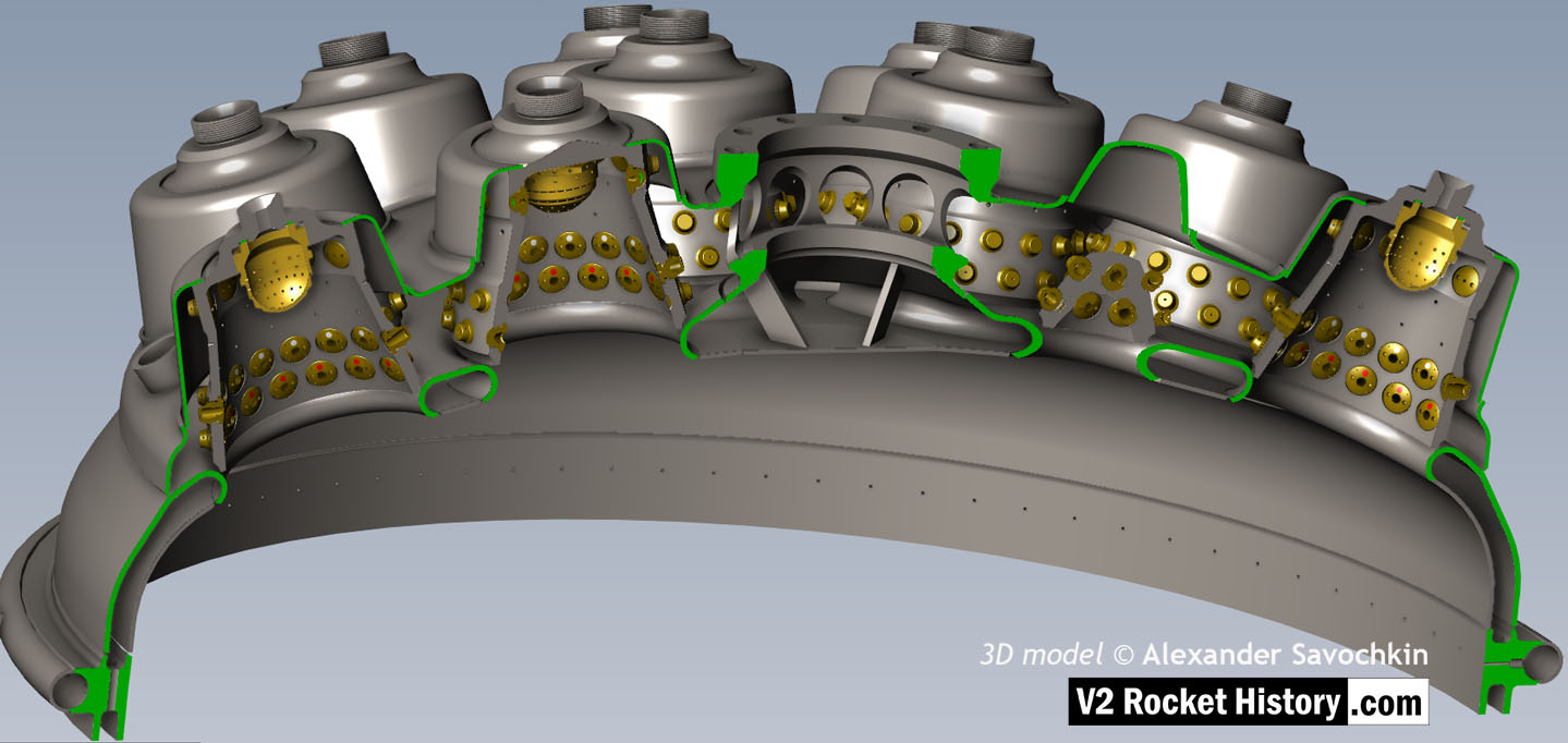
View of injector head showing 18 liquid propellant (LOX and fuel) diffuser cups and head fuel valve seating ring at centre, (see other images for insert and position nomenclature). Visible immediately below the valve seat are the large connecting holes that allow fuel to flow from the inlet manifold and cooling jacket to the injector space (some brass injector inserts can be seen through the holes) after the head fuel valve is released to be opened by the turbo-pump supply pressure. The four veil cooling inlet connectors are well shown as are two of the outlet connection holes immediately above them. 3D model by Alexander Savochkin
18-pot Head Fuel Valve Seat close-up
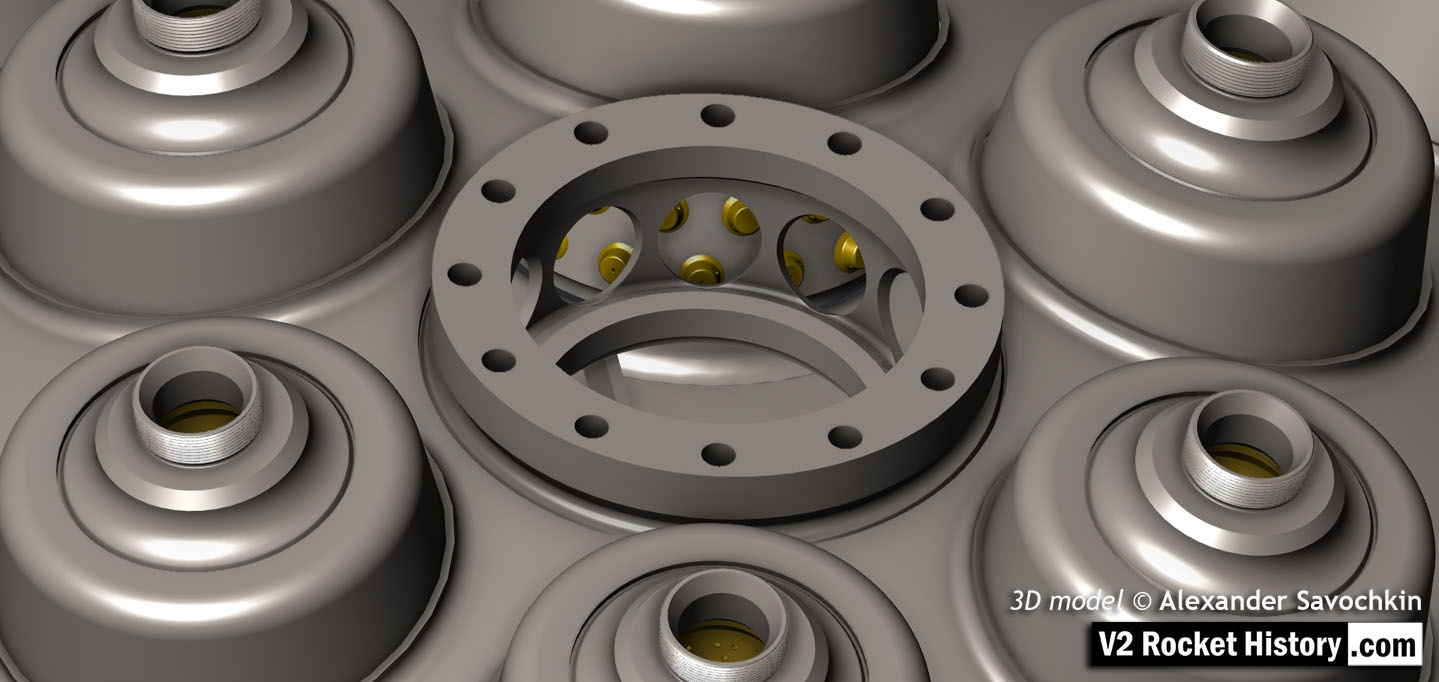
18-pot Head Fuel Valve Seat close-up
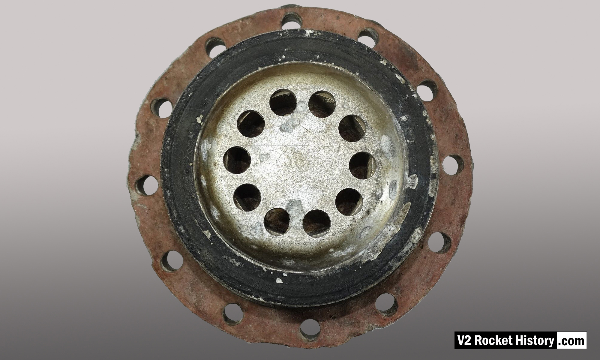
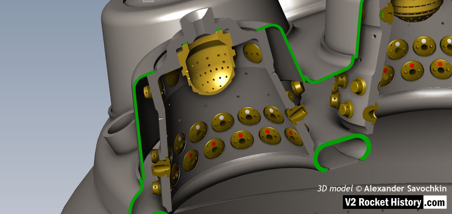
A close-up view of the head fuel valve mounting flange (showing 12 fastener holes). Visible immediately below the top flange are the large connecting holes that allow fuel to flow from the inlet manifold and cooling jacket to the injector space (some brass injector inserts can be seen through the holes) after the head fuel valve is released to be opened by the turbo-pump supply pressure.
18-pot head: Cutaway 2
18-pot head: Cutaway 2
Here the 18-pot head model has been cutaway to show the fuel cooling and fuel delivery spaces. the cooling jacket layer can be seen in the lowermost area of the head – below the centrally positioned fuel valve seat, between each cup at the lowest point, and ruining down toward the first set of veil cooling pores and the topmost coolant distributor ring. Note that the veil cooling system does not communicate with the regenerative cooling jacket and has its own feed pipes drawing fuel from the head injector space and not the cooling space. Visible immediately above the valve seat are the large connecting holes that allow fuel to flow from the inlet manifold and cooling jacket to the injector space after the head fuel valve is released to be opened by the turbo-pump supply pressure. 3D model by Alexander Savochkin
18-pot Cutaway 1
18-pot Cutaway 1
Liquid propellent (LOX and fuel) diffuser cup, showing three rings or echelons (A,D,& E) of brass injector inserts as well as two rows of drilled fuel feed holes. The LOX spray head is shown in the centre. Note the simple ‘shower head or watering can’ design of the LOX diffuser. A sealing washer can be seen fitted between the LOX diffuser and the steel cup. 3D model by Alexander Savochkin
Testing fuel injectors


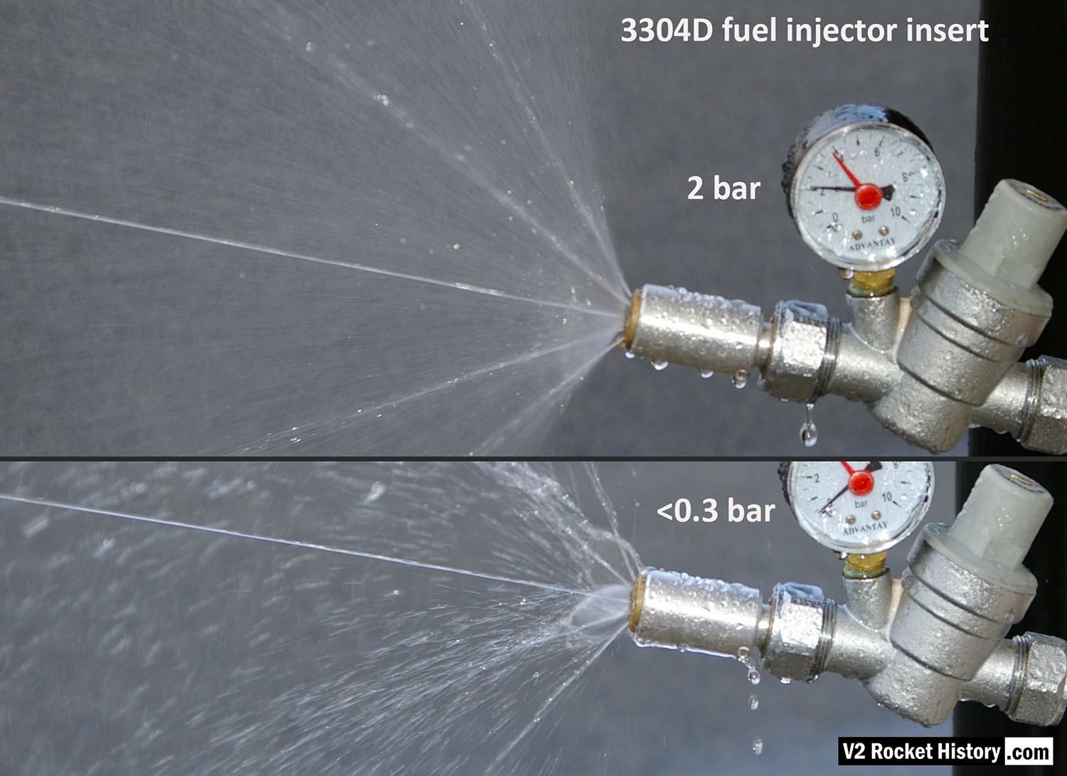
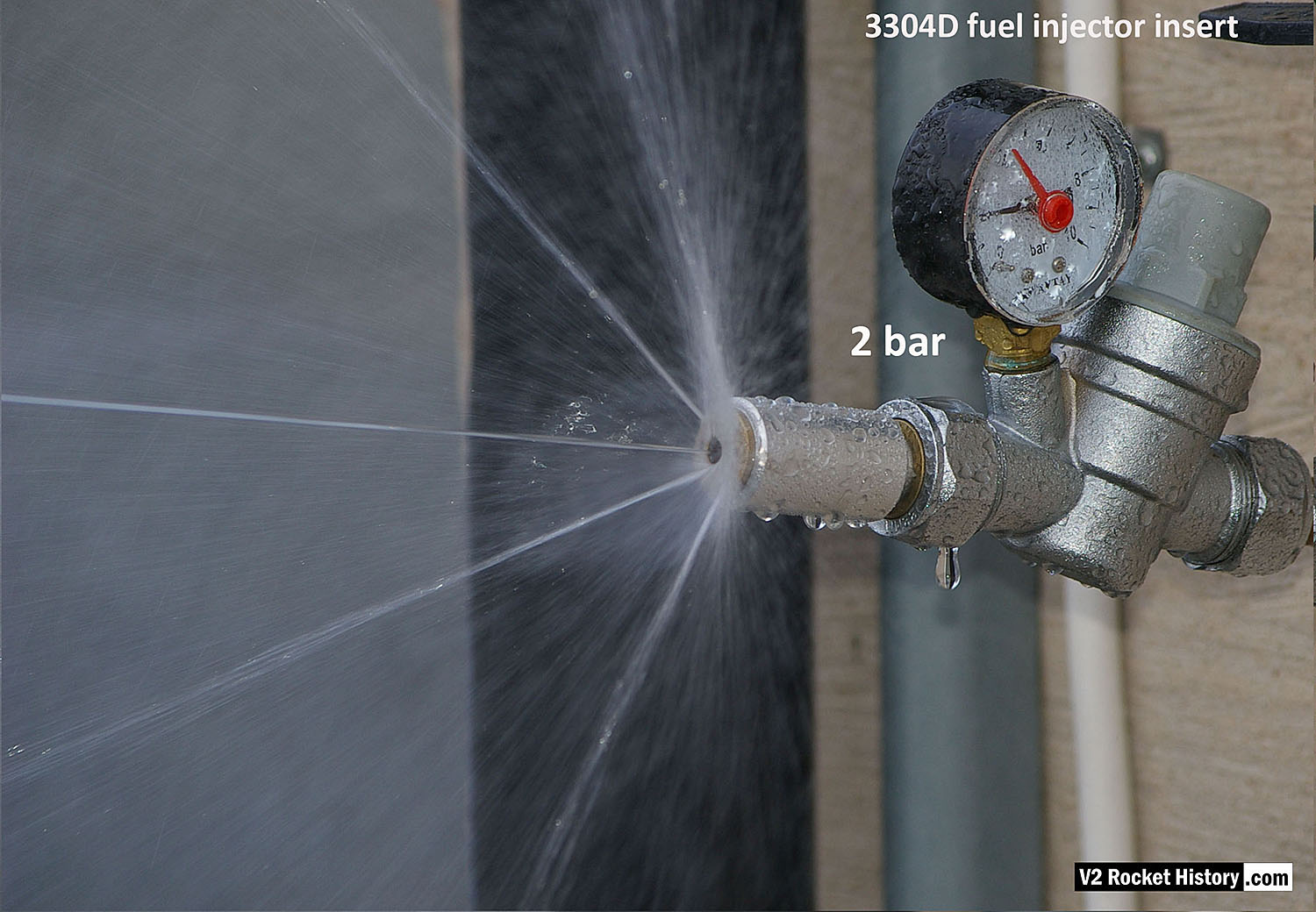

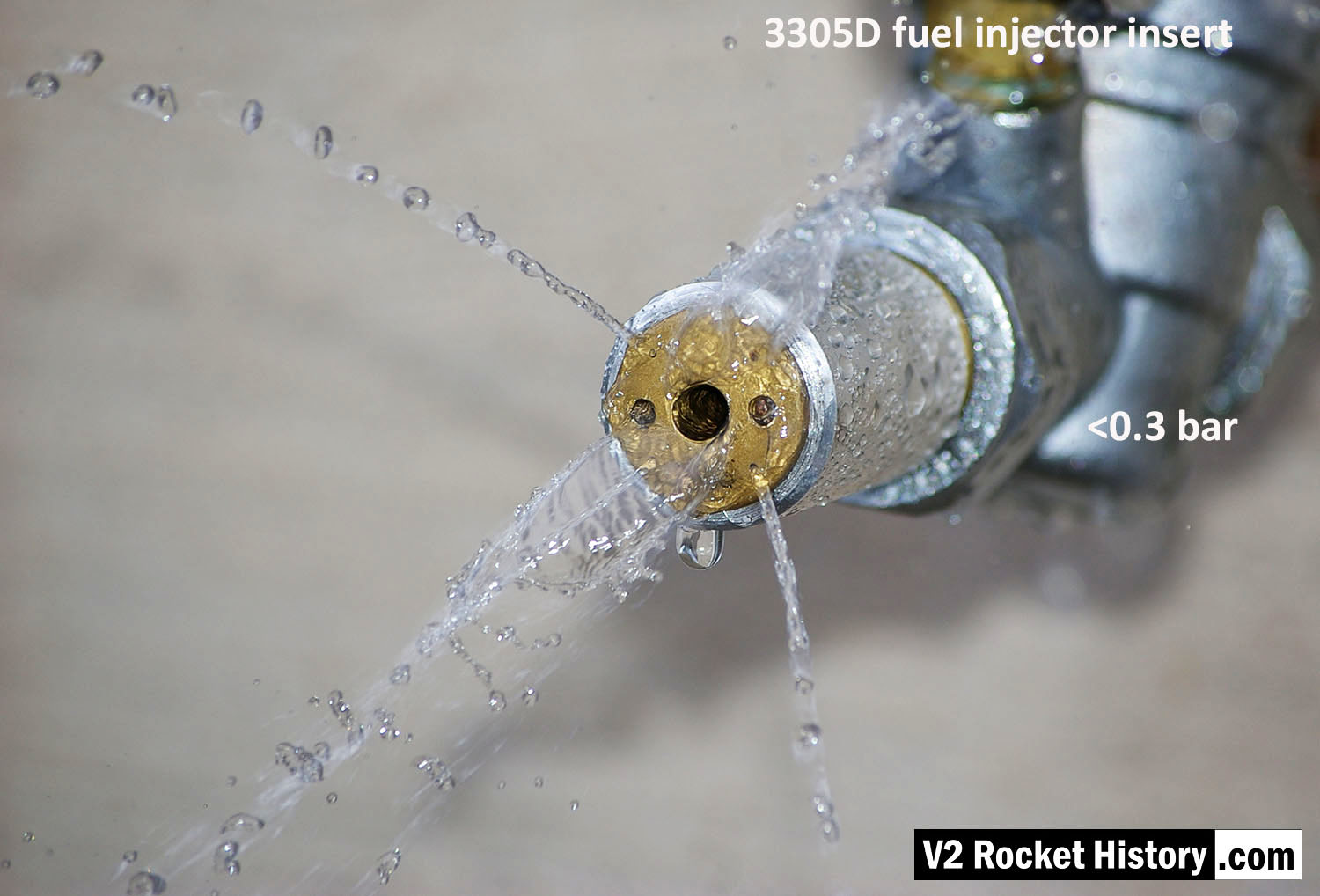
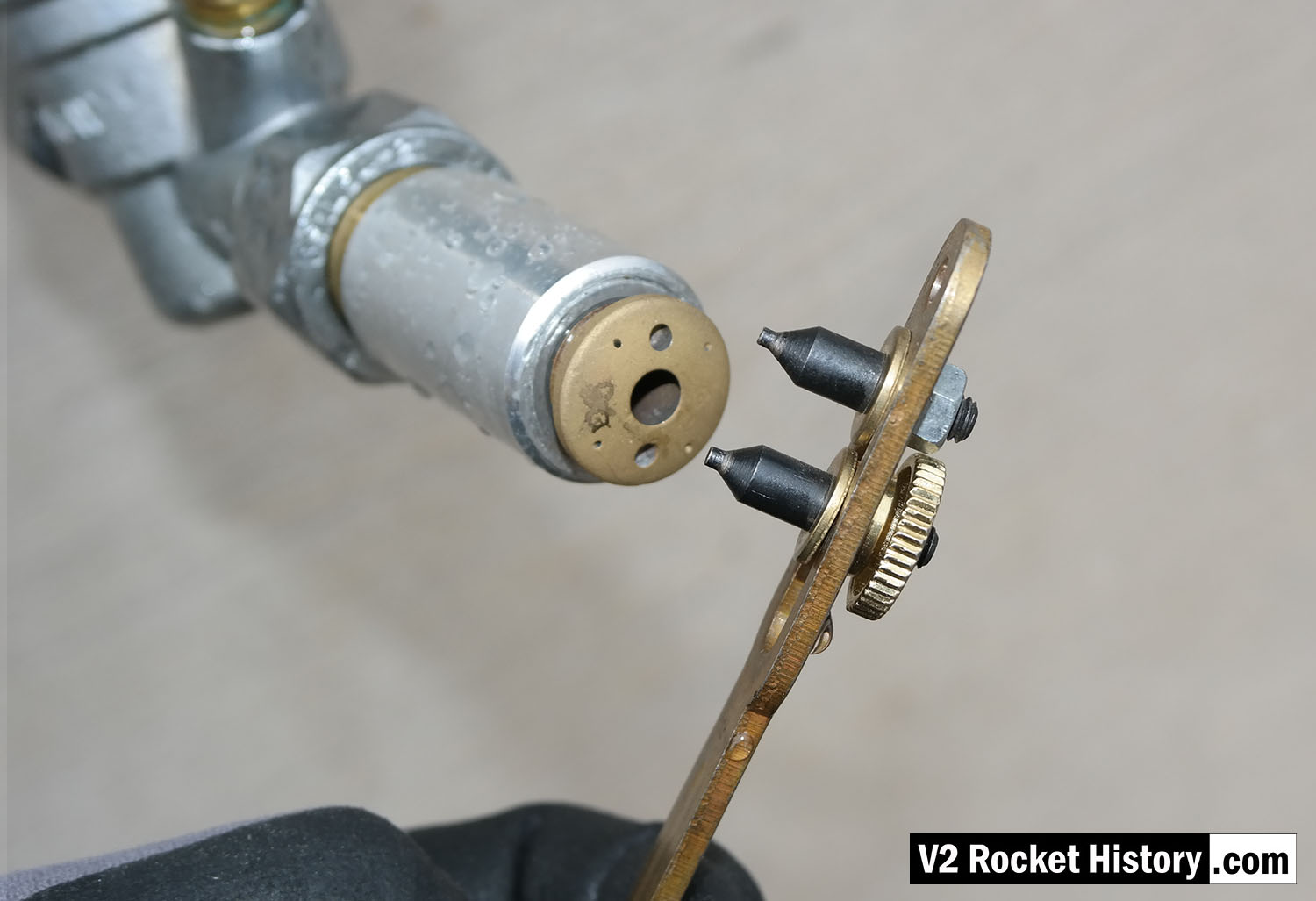


Testing fuel injectors


Description
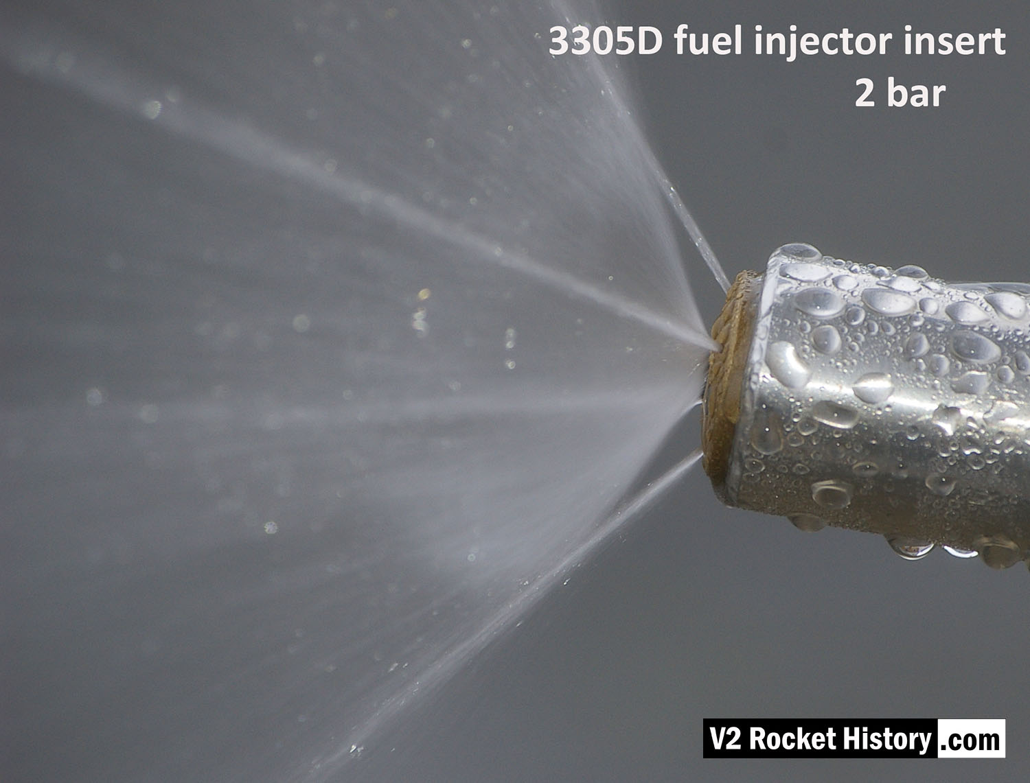
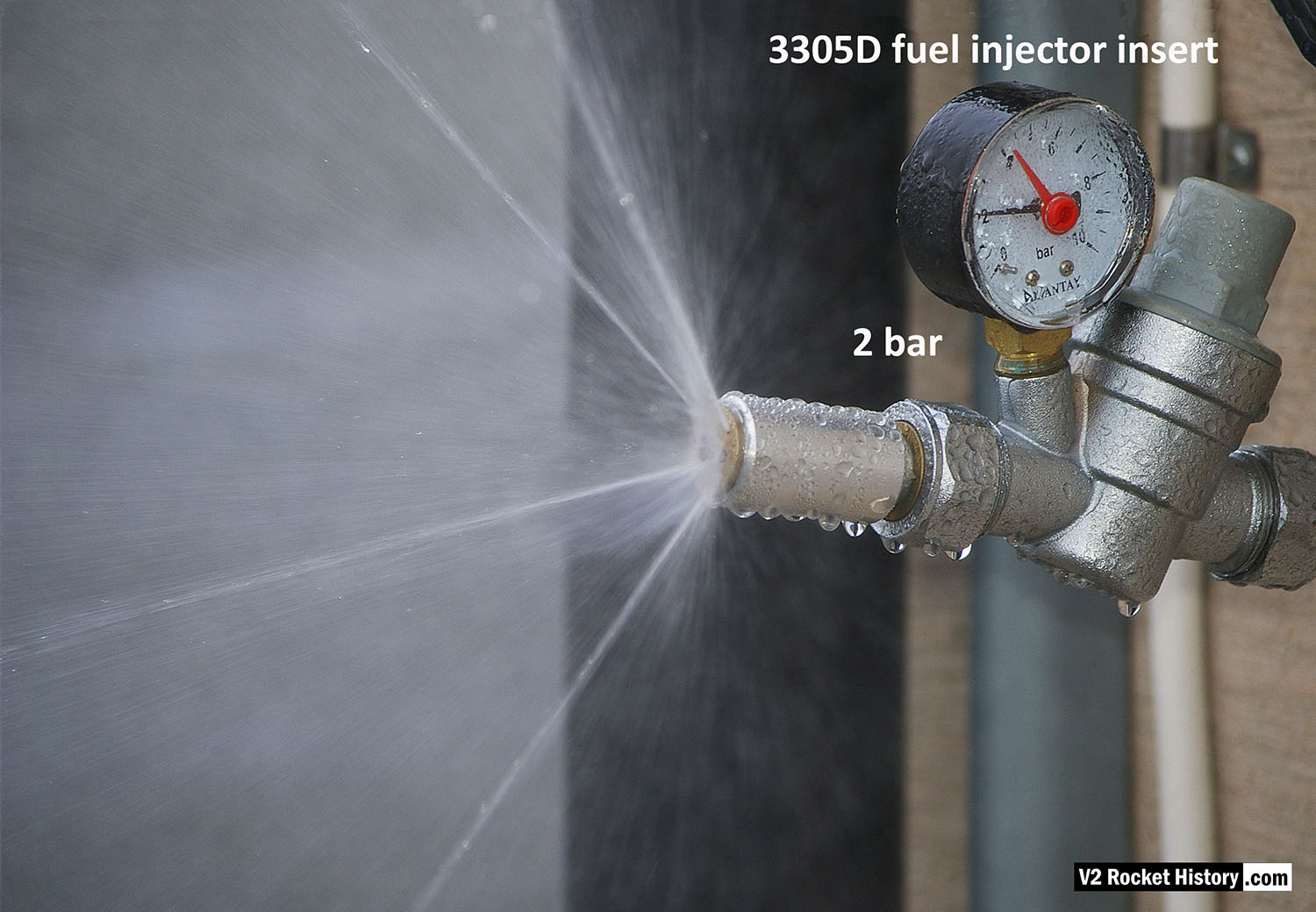
Image shows a correctly formed nebular cone attended by a fine mist. the four injector cooling jets are well shown, and although fluid beading can be seen on the face of the injector, there is insufficient liquid to cause dripping.
Location
