Archives: Gmedia Albums


Turbopump 3D CAD
3D CAD model images of the A4/V2 rocket engine’s steam turbine powered propellent pumps – all images by Ray Matter. To see Ray Matter’s blog 3D CAD modelling the V2 rocket turbopump introducing these images, just click the link.
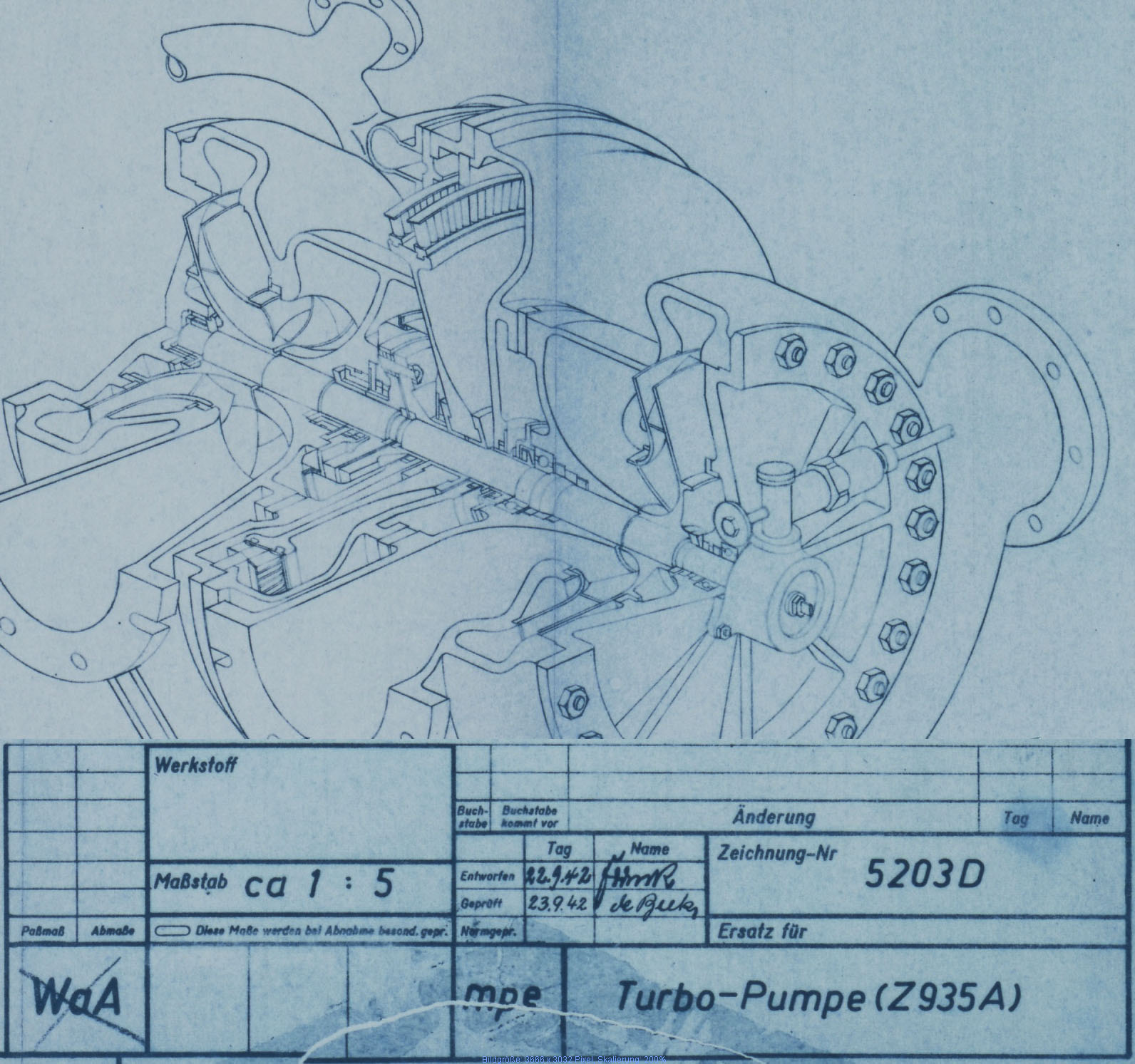
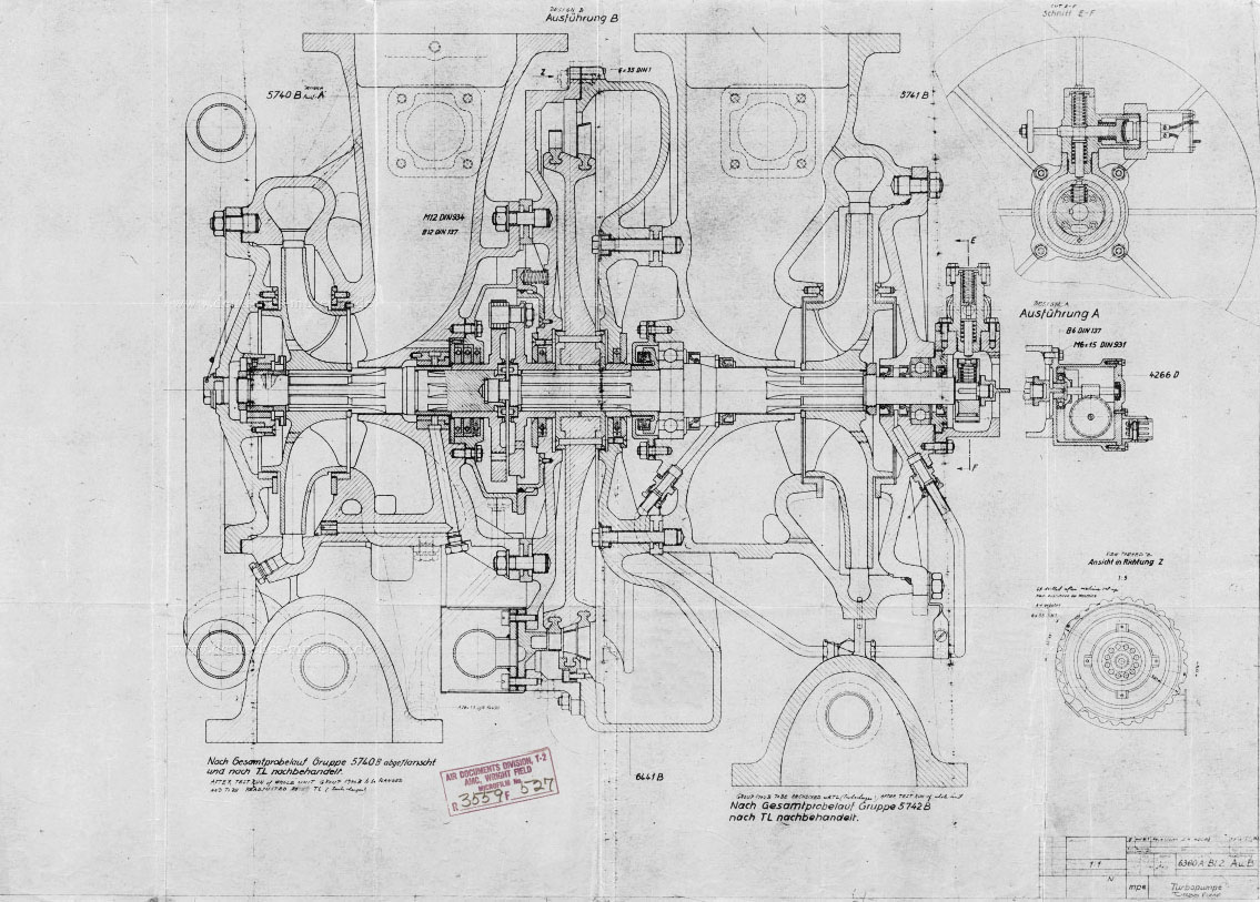
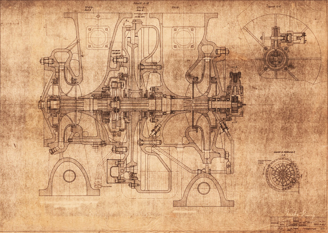
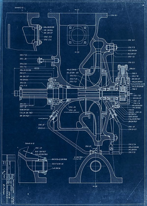
Sectioned general assembly view of the V2 turbo-pump (TP) dated September 1942. This image has been edited to show TP and document data closer together than the original.
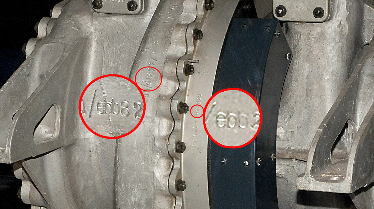
A complete V2 rocket turbo-pump on public display in the USA at the Smithsonian National Air and Space Museum in Washington DC showing Klein Schanzlin & Becker’s wartime contractor armament code – ebb. Smithsonian National Air and Space Museum exhibit.
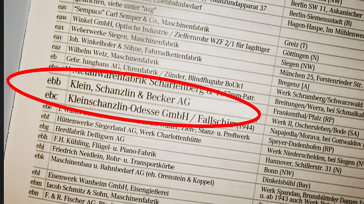
Page from the book, German Secret Armament Codes until 1945 by Michael Heidle (Visier Edition 2016) showing Klein Schanzlin & Becker’s wartime contractor armament code – ebb and Klein Schanzlin Odesse as ebc. ISBN: 978-3-944196-18-3
| Album | Turbopump parts and relics |
| Category | Turbo-pump |
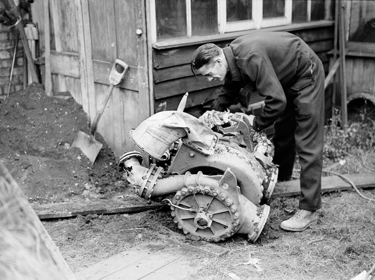
V2 rocket turbo-pump from a missile fired from Walcheren, Serooskerke, Vrederust, by battery no 444, at around 7am on September 17th 1944. The missile impacted East Ham with a direct hit on houses. Killing 6 people with 15 seriously injured. Much of the rocket debris was taken to the East Ham police station for examination by the military authorities. The serviceman in the picture is feeling the steam inlet manifold as it is still warm to the touch. Information porovided by www.v2rocket.com.
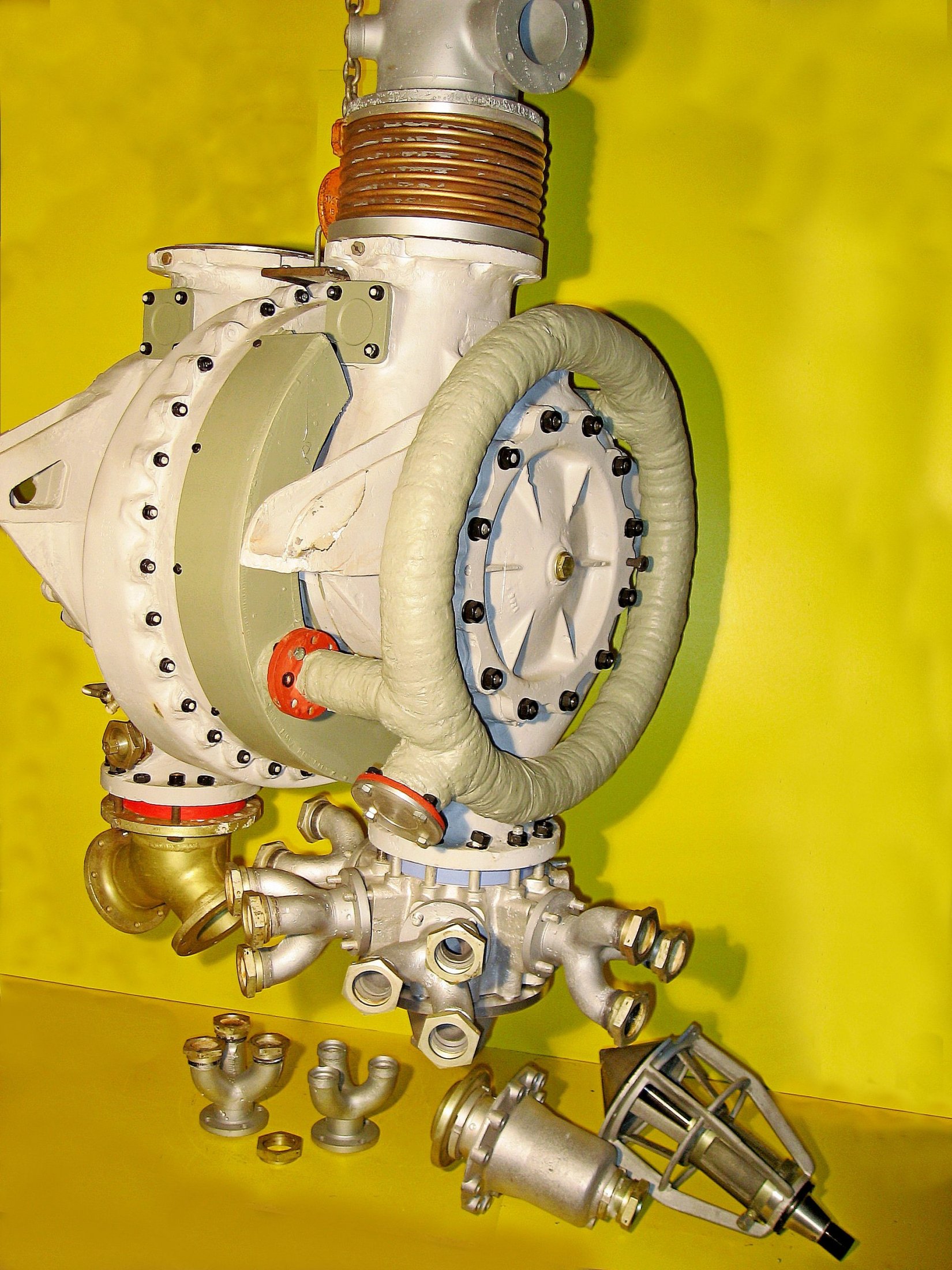
A4-V2 turbo-pump (TP) assembled from original unflown and refurbished flown parts by Horst Beck. Although this rebuilt TP is an accretion of parts from various origins and eras (from 1943 to 1945) the main cast parts of the TP, the turbine housing, and pump cases, were manufactured no earlier than December 1944.
The TP is orientated so that the LOX pump is to the right and the lagged steam inlet and distribution manifold is well shown, running around the circumference of the LOX pump face plate.
The manifold flange, that connects to the output of the steam generation plant, is shown capped off. One of the two TP steam inlet points can be seen above and to the left of this flange. The other inlet pipe can just be seen 180 degrees away on the other side of the manifold.
It is worth noting that he TP presented here is marked ebb (ebb = KSB) in various locations, if any demonstration was needed that KSB was still a primary supply contractor for this critical component in December 1944. See next image in this sequence for an explanation of the blue and red spacers that can be seen where the TP outlet flanges connect to the fuel and liquid oxygen (LOX) outlet splitters. Image courtesy Horst Beck Collection
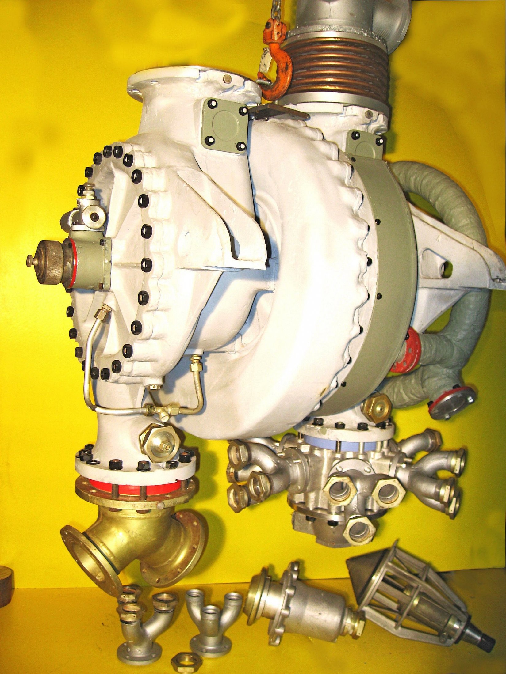
A4-V2 turbo-pump (TP) assembled from original and refurbished parts by Horst Beck. See previous image in this album for more details of TP.
The pale blue spacer that can be seen inserted between the lower LOX outlet flange (on the right of the TP) and the red spacer located in a similar position on the fuel outlet side (left) are critical adaptions to standardise the propellant flow on the basis of test runs performed on each TP. The red and blue spacers are chokes (essentially large washers) that were sized according to the needs of each individual pump. One or sometimes both spacer/washers would have a reduced holes to choke the flow volume to the correct rating relative to the other pump and the overall specifications.
The small pipe network, shown linking the underside of the fuel inlet case, with the bottom of the fuel pump (FP) case and the bearing area of the FP face plate, was used to allow a small continuous flow of propellant pass to the bearings as lubricant – the surplus was dumped overboard via the unconnected union in the middle of the pipework (and nearest viewer). A similar propellant lubrication system was used on the LOX pump – critically LOX can not be allowed to come into contact with conventional organic lubricants as there is a risk of an explosion. So using the material being pumped as the bearing lubricant is a good solution to this problem. Image courtesy Horst Beck Collection
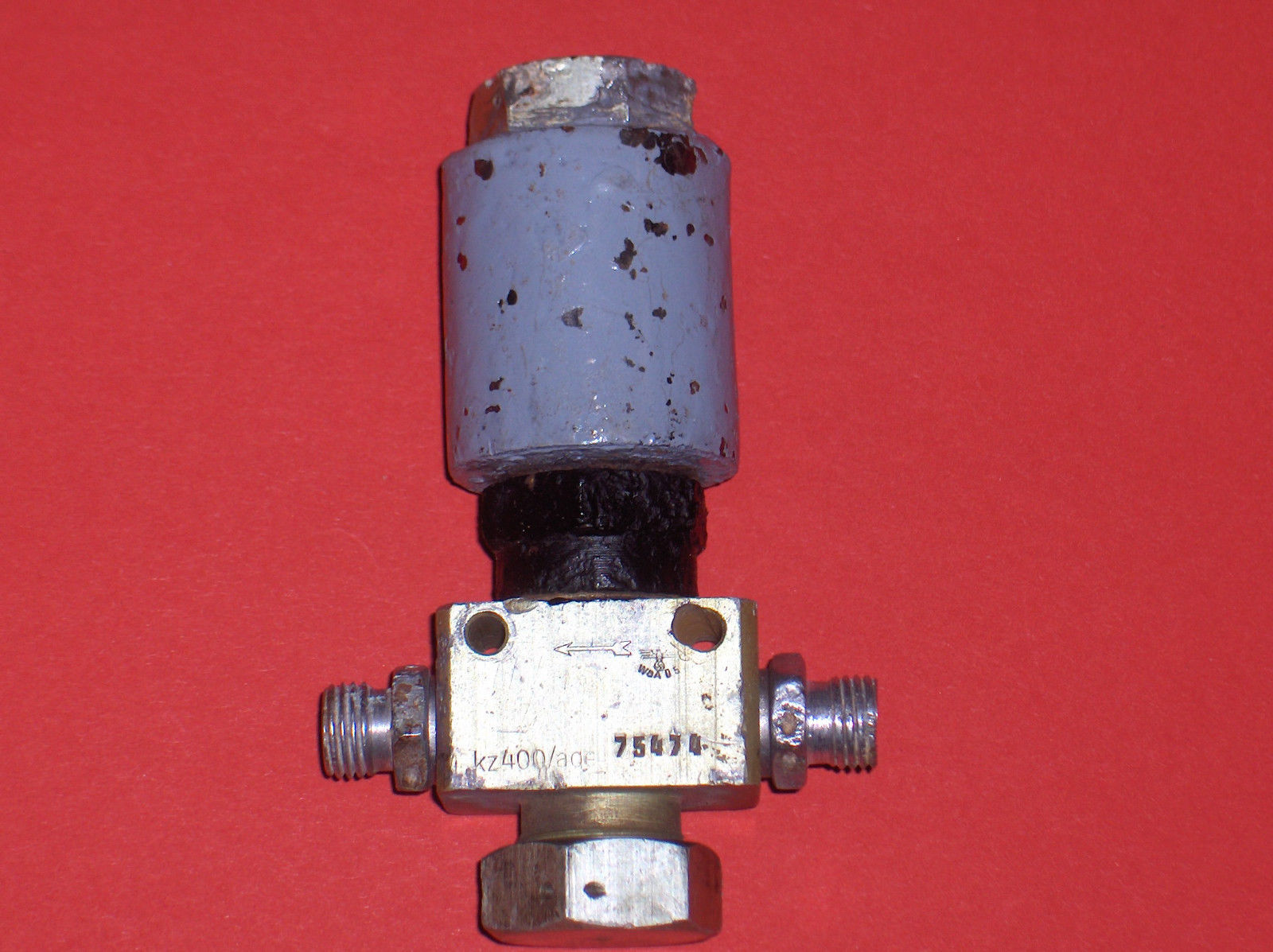
Solenoid electro-magnetic air valve. The This valve type is used numerous times to control equipment in the V2 missile. Variations of this electrically activated valve can be used to control high pressure air or fluids.
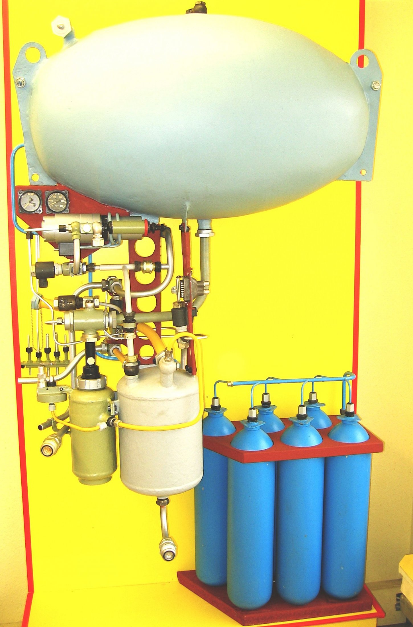
This photo shows an excellent presentation of the gas (steam) generation plant assembled from carefully refurbished flown and unflown V2 missile parts by Horst Beck.
The display shows the large elliptical H2O2 (80% test strength hydrogen peroxide) tank at the top of the assembly and the smaller sodium permangenate reservoir below. The smaller cylinder to the left of the sodium permanganate tank is the steam generation chamber sometimes referred to as ‘the disintegrator’. The rack of blue painted cylinders, that look and function just like ‘scuba’ tanks, are part of the V2’s on-board nitrogen gas (air) reservoir employed to power the missile’s various pneumatic control valves. A second nitrogen reservoir was held in the equipment bay near the top of the missile. Image courtesy Horst Beck Collection
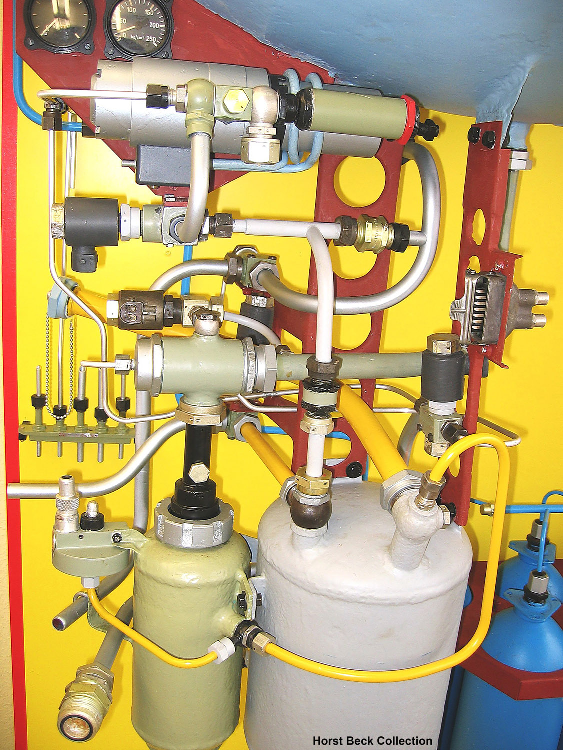
A4 missile steam generator detail. This excellent presentation was rebuilt from original refurbished parts by Horst Beck. See our video article The V2 Rocket Turbo-Pump for a technical exposition of the parts shown in this photo. Image courtesy The Horst Beck Collection
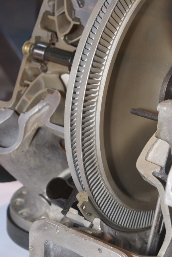
This image shows a cutaway of an A4-V2 turbo-pump. The section reveals the Curtis type 2-stage steam-turbine rotor and you can also see part of the stater inserted between the blades (bottom middle) and the adjacent steam distribution pipe (black open pipe on stater’s immediate left). Top left, a centrifugal pump rotor can be seen – cut through, it shows a multi-splined shaft running through the centre, simple bearing and end-cap.
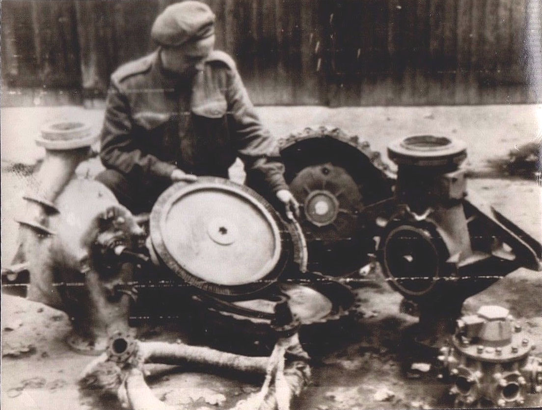
Image shows allied soldier examining remains of V2 rocket turbo-pump after impact. The soldier is holding the steam turbine rotor – the large size of this part is well shown in this photo. The still lagged steam inlet manifold can be seen in the left foreground and the LOX outlet manifold (and valve, topmost) can be seen in the lower right corner.
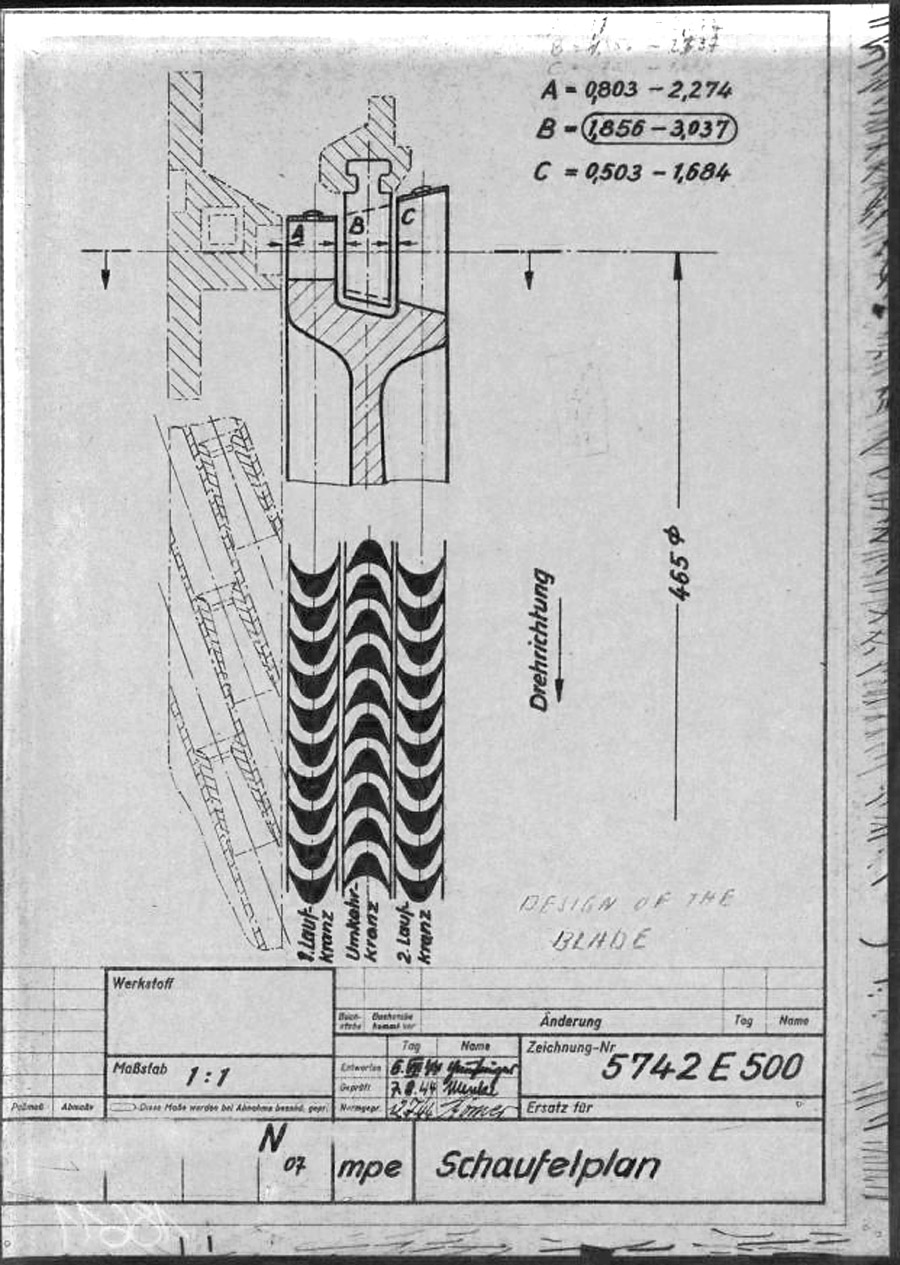
This mpe* drawing from 1945 shows the individual steam buckets or blades (labeled A and C) mounted to the rim of the rotor disk. As well as the fixed (i.e. stationary) stater blade B, positioned such that blades A & C can pass either side of it. The steam expansion is well shown by the increasing surface area of the blades from A to C, and growing larger, from left where the high pressure super heated steam enters the turbine, to right where it exits the blade pathway and passes in to the exhaust outlet. The lower graphic shows the way the super-heated high pressure steam is passed from the initial A blade and deflected by the reversed B stator blade for its energy to to be harvested for a second time by the C rotor blade. * mpe is the secret three letter armament code for Karlshagen, Werk Nord (North Works).
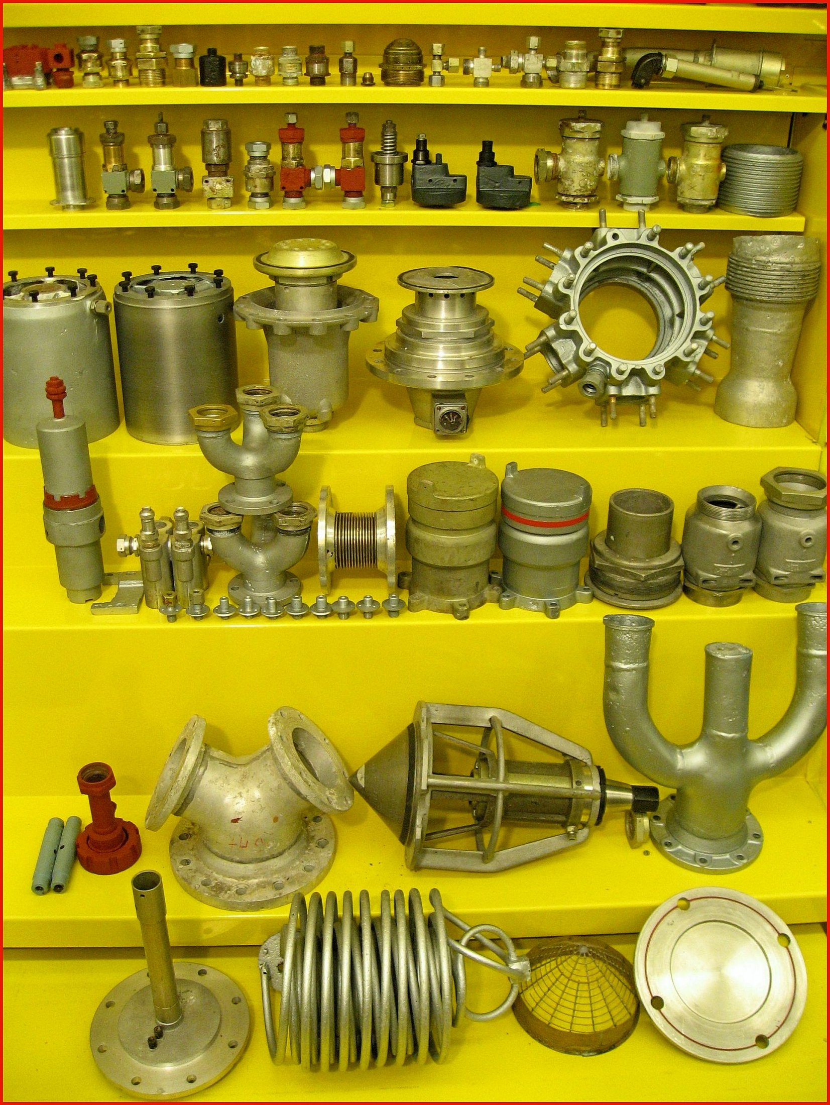
Looking rather like a a display in a V2 rocket shop window, this terrific display, centered on propellant supply parts, is part of the Horst Beck Collection and provides an unparalleled opportunity to view original A4-V2 missile components in a near-new condition and isolated from other equipment. Rare items include: a heat exchanger coil, for the volatilisation of LOX (2nd from left bottom shelf). An H²O² choke pipe and steam generator pot cap, (in red oxide paint, 2nd shelf up from bottom) Alcohol tank valve (2nd from right on the same shelf). Alcohol down-pipe 3-way splitter (1st item on right same shelf). LOX manifold 3 to 1 splitter (two with one resting on the other, 3rd shelf up on left). Two LOX main tank valves, (4th shelf up, first two item from left). Injector head main alcohol valve (same shelf, 3rd item from left). And on its right, a main Lox dual valve, and on its right LOX distribution body, minus valve. A ‘Preshona’ non-return valve can be seen (2nd shelf from top, 5th item from left). The two same shape black items (2nd shelf from top, middle) are two Sodium Permanganate diaphragm contact switches (Backfile code D2R). The next 3 items to the right of these are all H²O² 25ton valves. The large brass item in the middle of the top shelf is a LOX spray cap. Image courtesy Horst Beck Collection
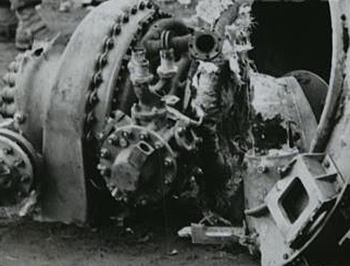
Picture shows tubo-pump debris from impact site. LOX manifold clearly seen (3 in 1 outlet pipes, upper center of image – the one to its right, 2 o’clock position, and left, 11 o’clock position are both broken off).The LOX flow electric control valve is also well displayed in this image (LOX valve head is slightly low and left of center, part nearest camera). The electrical connection to the LOX valve has broken away leaving its empty socket pointing upwards and to the right.
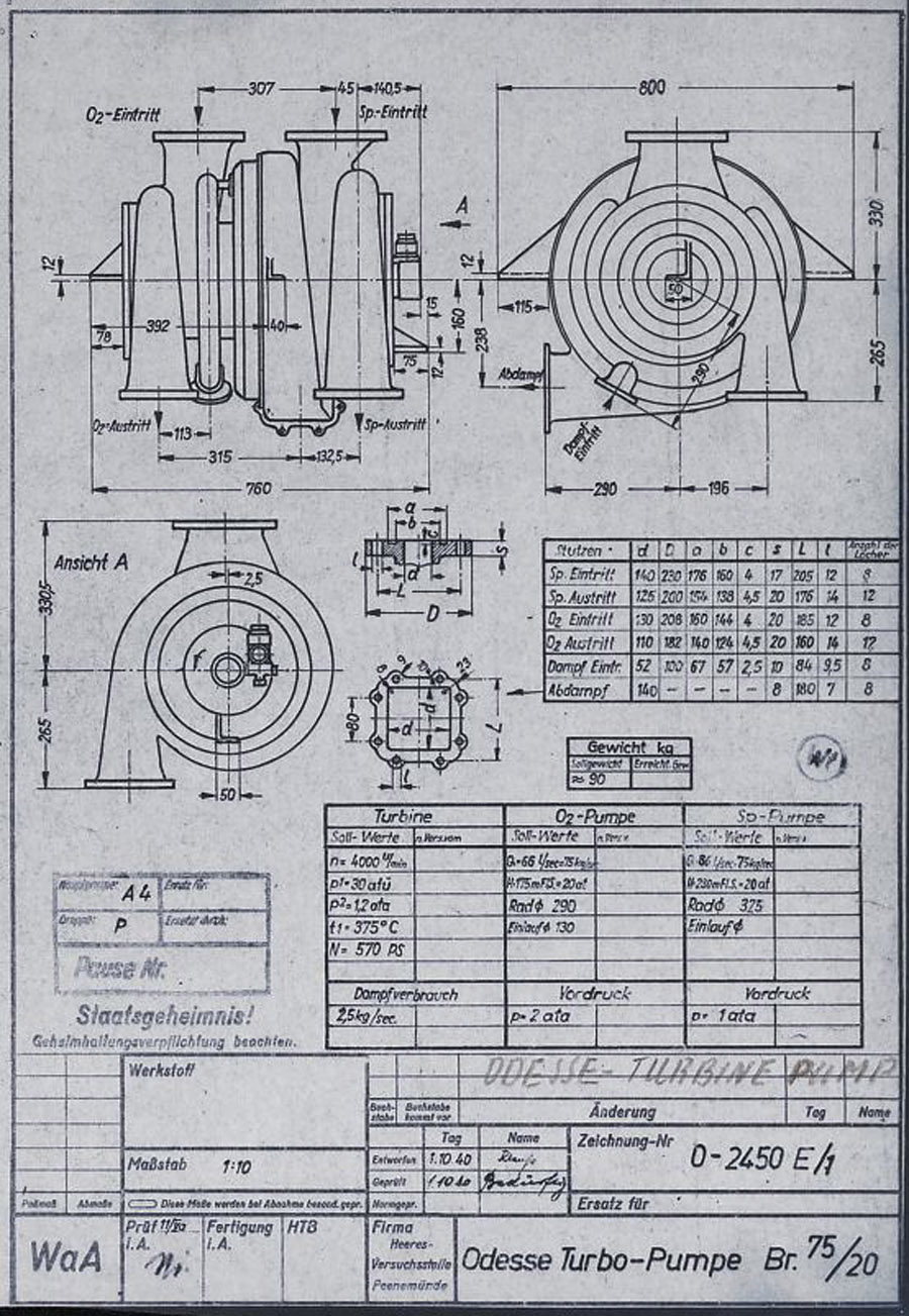
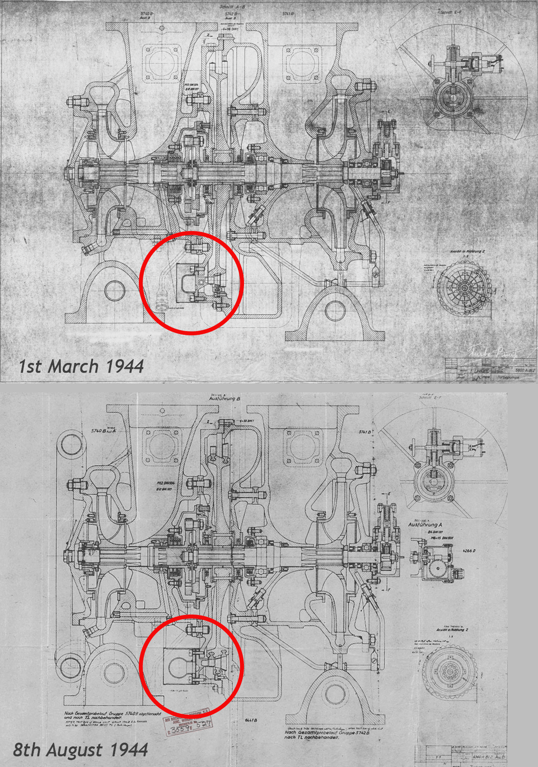
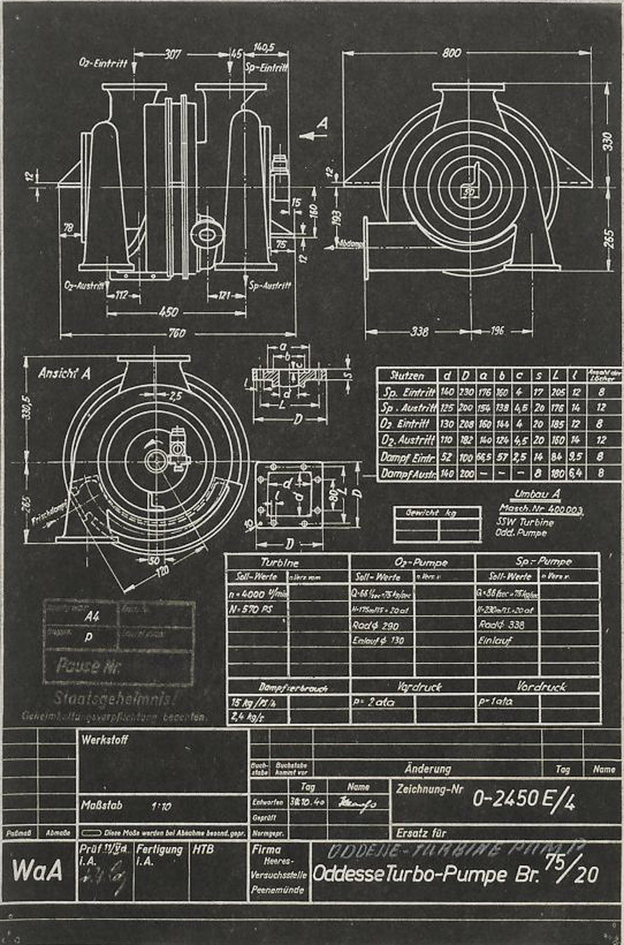
This HVP technical drawing from October 1940, shows a proposal from the Oddesse company – the full title of this company is KLEIN SCHANZLIN ODDESSE GmbH. Klein, Schanzlin & Becker A.G. (waffenamt code: ebb) took over Oddessa in 1929 and the company became formally known as KLEIN SCHANZLIN-ODDESSE GmbH (code ebc) in 1939. (NB: The company name has nothing to do with a similar sounding place name Odessa. The Oddesse trading name was formed from the partnership of English engineer Oddie, and German businessman Hesse.). The dual centrifugal turbo-pump shown in the drawing is a variant of a high pressure fire-fighting pump manufactured by Oddesse. Note the off-center outflow ports – not also that the outlet flanges are still level at this stage. Note also the incorrect spelling of the company name in the details panel lower right. (Digipeer.de image)
Another HVP technical drawing from later in October 1940, shows further data from the KLEIN SCHANZLIN ODDESSE (ebc) company A4-V2 turbo-pump project. See previous image for company details. The dual centrifugal turbo-pump shown in the drawing is a variant of a high pressure fire-fighting pump manufactured by Oddesse. Note the off-center outlet ports. Note also the corrected spelling of the company name in the details panel lower right (see previous Oddesse image) and the small note below the top table that indicates that the pumps are from Oddesse (ODD) and the turbine from a company indicated as SSW. (Digipeer.de image)
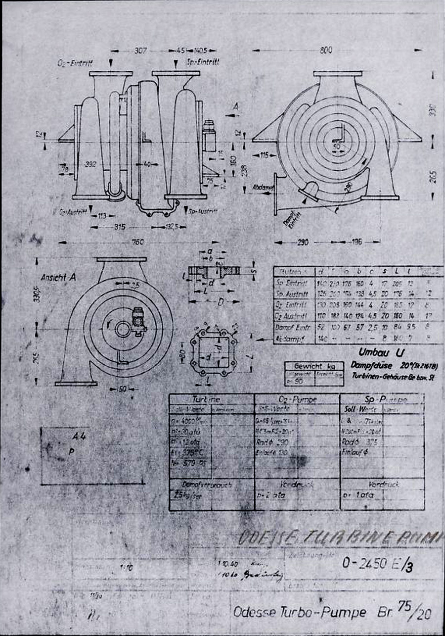
Signatur FA 014/21241 (Digipeer.de image)
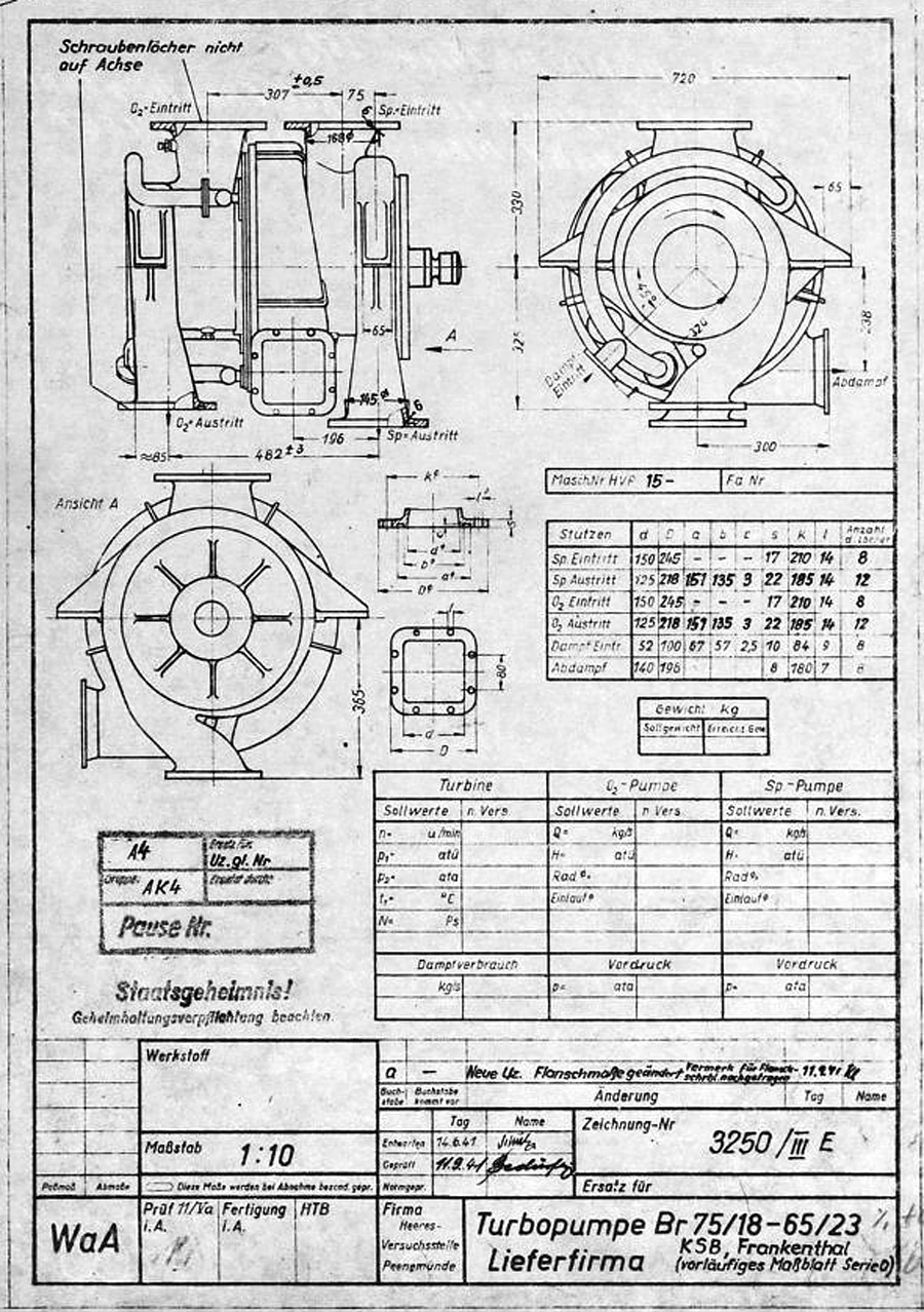
V2 rocket turbo-pump preliminary dimension sheet for O series, drawing. Many of the final elements of the turbo-pump design can be seen in this ‘preliminary’ drawing and table form 1941. The word lieferfirma in the data box btm right mean supply company – and this is indicated to be KSB or Klein Schanzlin & Becker AG, Frankenthal. Signatur FA 014/14769
(Digipeer.de image)
Signatur FA 014/02537
Abmessungen: 42,9×59,8
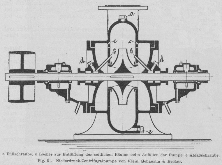
Early belt powered centrifugal pump by Klein Schanzlin & Becker. This schematic shows an early 20th century centrifugal pump designed and manufactured by KSB. The drawing appears to show auto-purge pathways at points marked C as well continuous lubrication pathways at B. Both of these important ideas would later feature in the propellant pump of the A4-V2 missile.
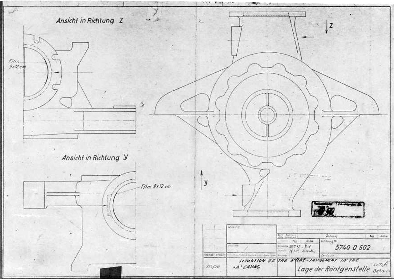
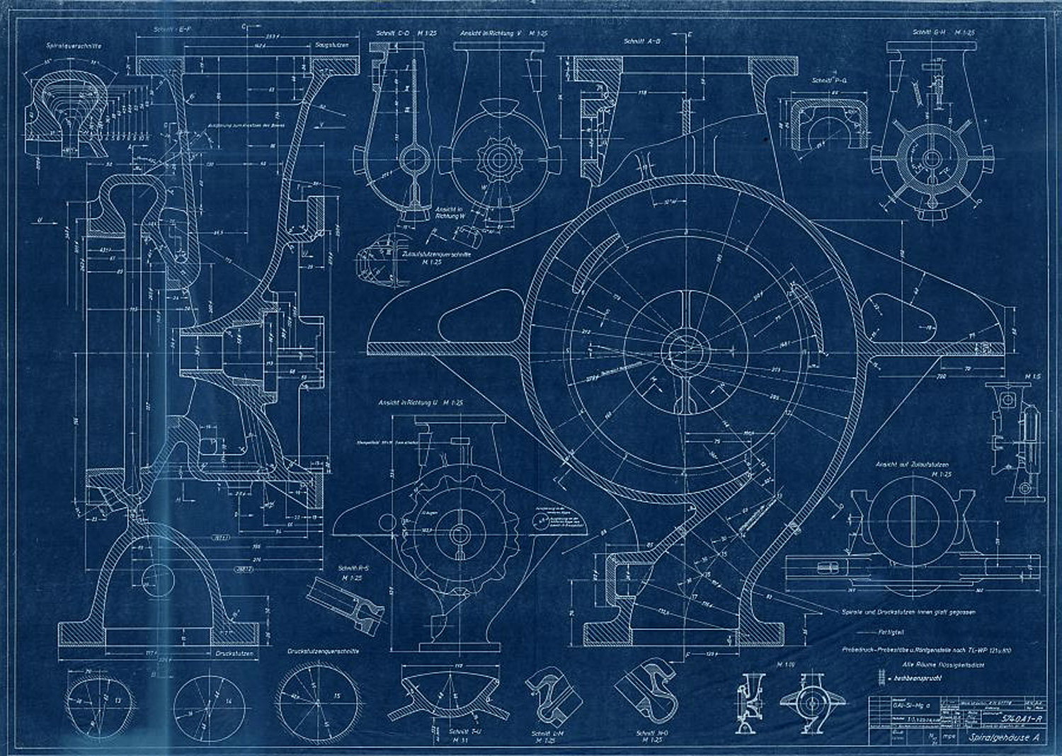
A Stoff (liquid oxygen) pump casing diagram showing stress points that require X ray quality control photography before use. The diagram shows the specific locations where photographic film is to be placed for X-ray analysis.
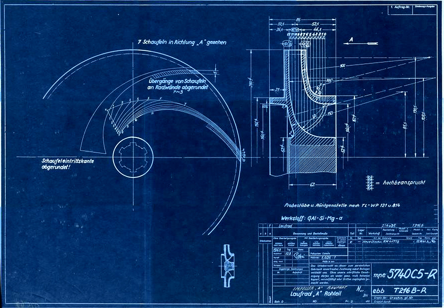
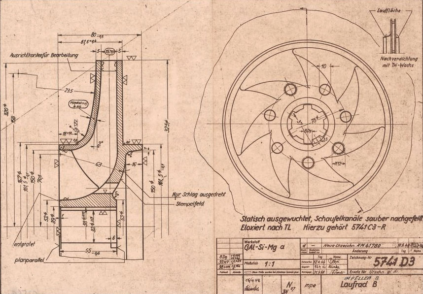
Centrifugal impeller for A or liquid oxygen (LOX) pump. The drawing originated in Aug 1943 and was superseded in December 1944. A key to the image hatching can be seen with the label ‘Hochbeansprucht’ which in English means Highly Stressed. Next to the drawing numbers two secret three letter armament codes can be seen indicating the ‘origination’ of the document. The top one mpe = Heimat Artillerie Park 11 (HAP or Army Artillery Range). The lower code ebb = Klein Schanzlin & Becker AG, Frankenthal.
Signatur FA 014/02542 (Digipeer.de image)
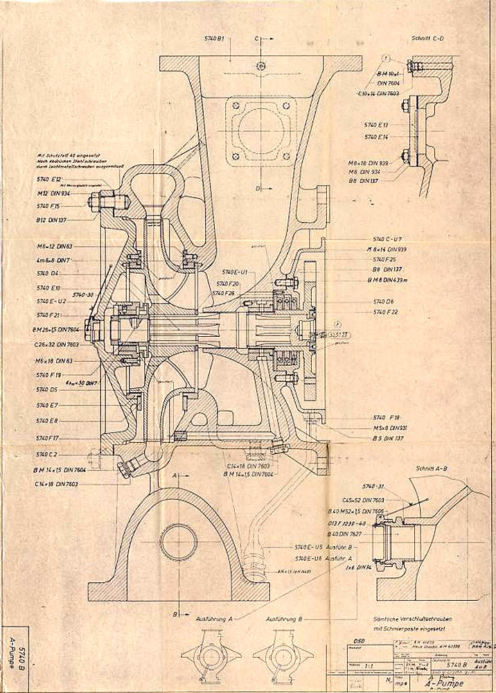
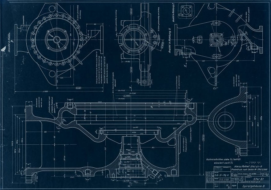
Signatur FA 014/02534
Abmessungen: 60,5×82,9
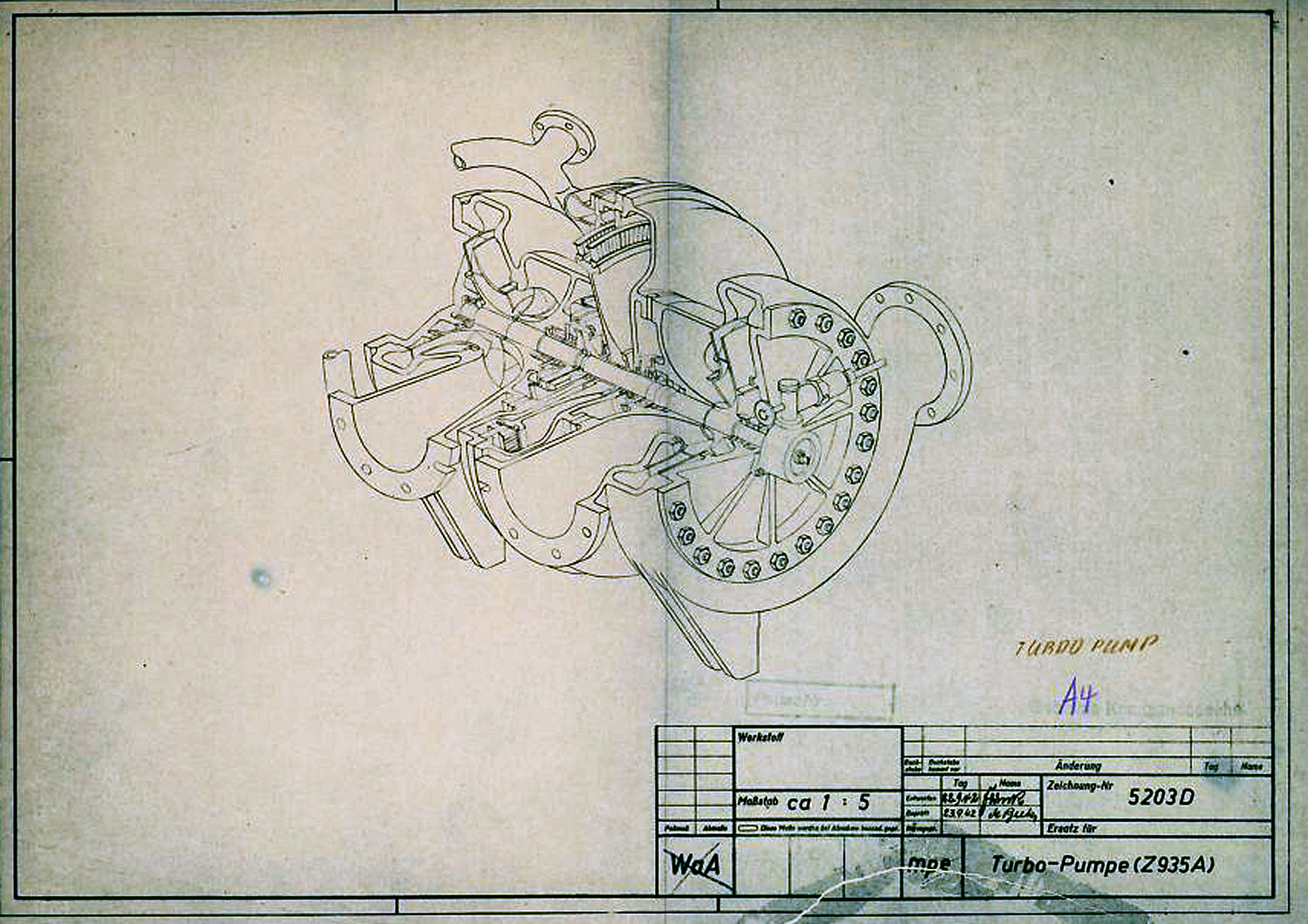
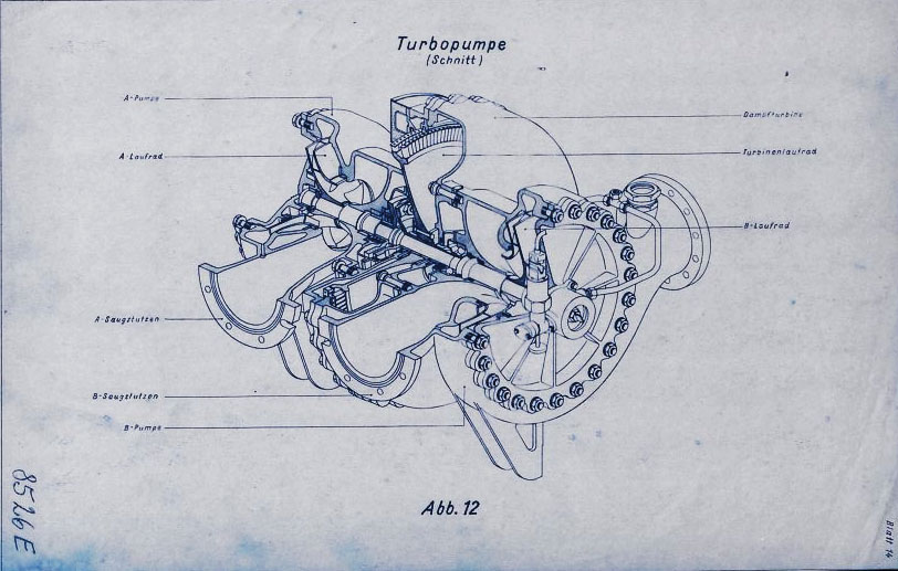
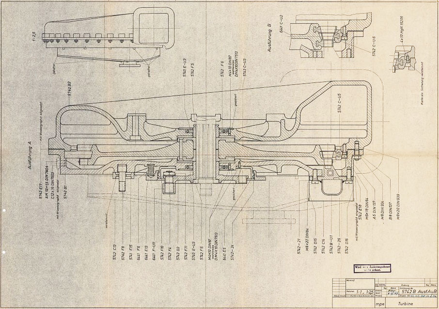
In this diagram the V2 Turbo-pump is shown in a cutaway presentation and rotated 90 degrees counter clockwise. The B stoff (fuel) pump is nearest the viewer – the over-speed device can be seen on the B stoff pump’s case end-plate. The low pressure inlet ports our shown to the left, and high-pressure outlet ports are on the right. The steam distribution manifold can be seen at the furthest point from the viewer – the steam inlet pipe flange can also be seen. The feed pipe from the steam generator attaches to thus flange.
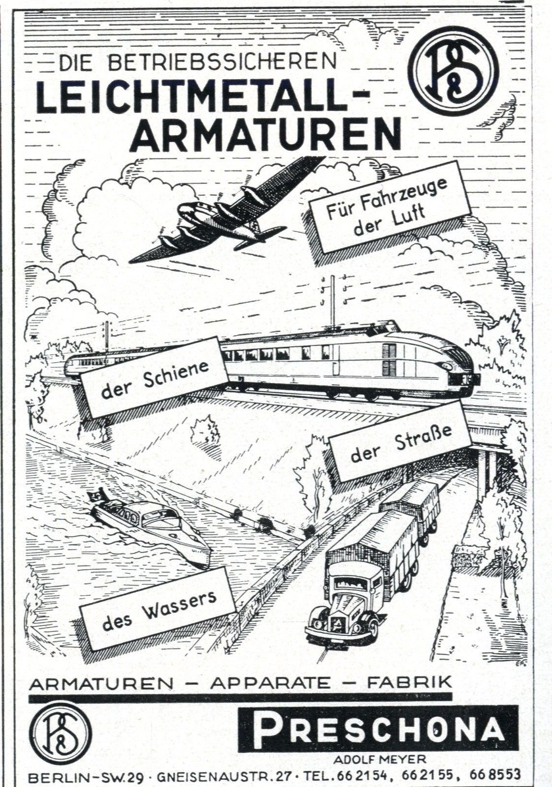
Trade literature advert for the Preschona company (Adolf Meyer) in Berlin, Germany. The company was a supply contractor and (among other items) manufactured the non-return valve for the steam turbine exhaust heat exchanger, employed to volatilise a small portion of liquid oxygen (LOX) to pressurise the LOX tank to maintain critical flow volume to the LOX turbo-pump.
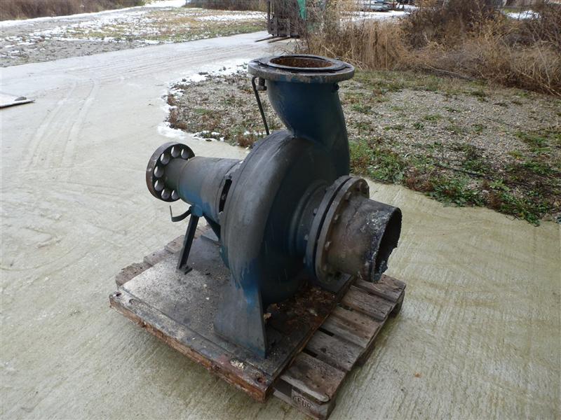
Large industrial volute case centrifugal pump by Klein Schanzlin & Becker. This image highlights the ‘genetic’similarity and family resemblance between KSB’s current and historical product range and the visible features of the A4-V2 missile Turbo-Pump (TP). Apart from the general shape of the cast spiral-volute case and its connection flanges, the ‘soft’ shaft connection (disk with holes on the extreme left of the pump) is very reminiscent of the semi-flexible shaft connection point linking one side the steam turbine rotor shaft to the shaft carrying a propellent pump rotor seen in the A4-V2 missile TP. Family photo? Industrial volute case centrifugal pump by KSB
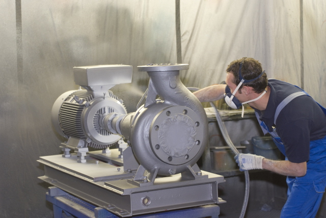
Electric industrial volute case centrifugal pump by Klein Schanzlin & Becker. This image highlights the ‘genetic’similarity and family resemblance between KSB’s current and historical product range and the visible features of the A4-V2 missile Turbo-Pump (TP). Assembly is shown being spray painted.
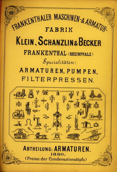
Cover of catalogue published in 1880 showing the KSB product range
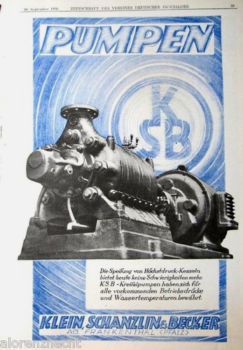
Klein Schanzlin & Becker electric centrifugal-pump advert.

Valves
Images of the main valves involved in the propellant flow of the A4 / V2 liquid fuelled rocket engine
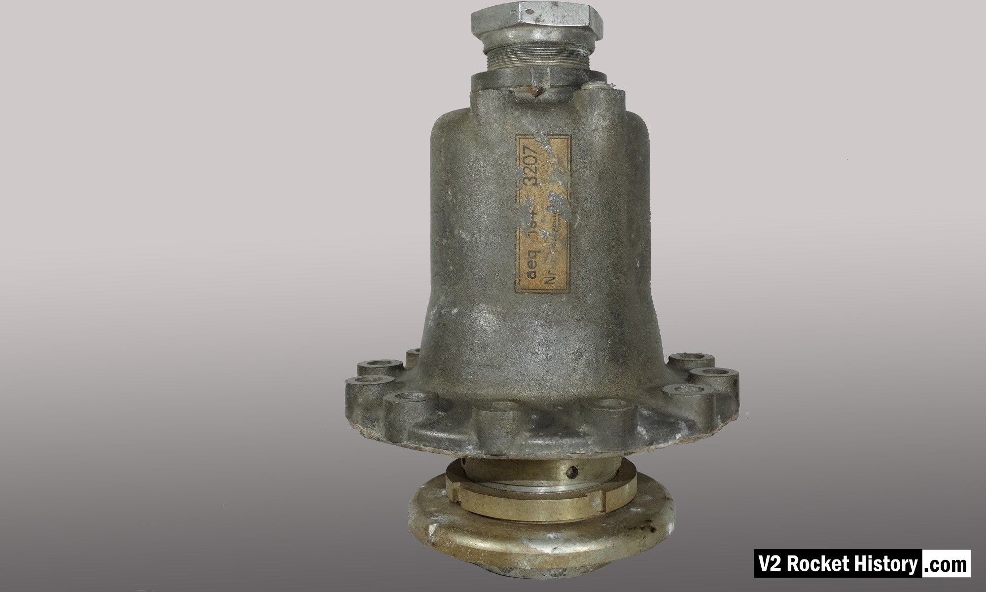
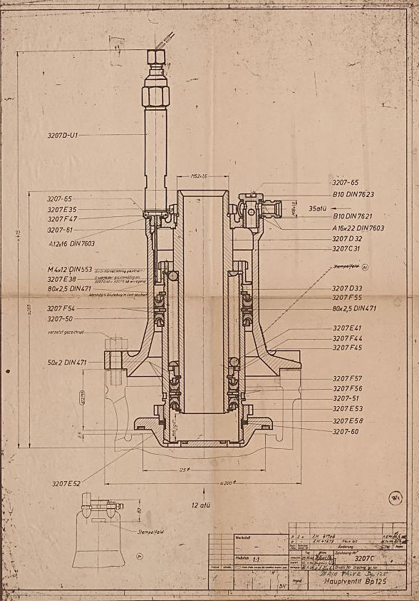
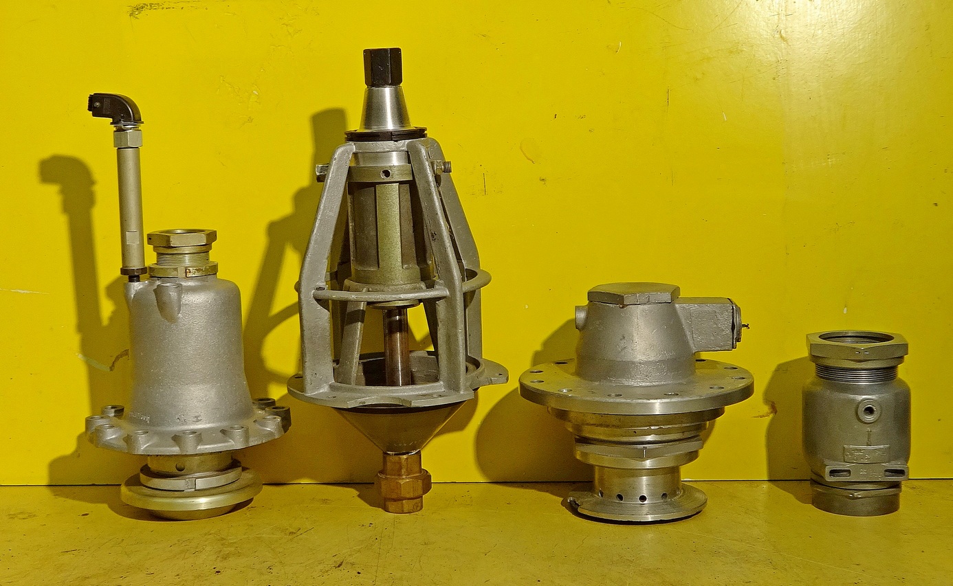
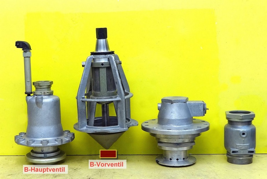
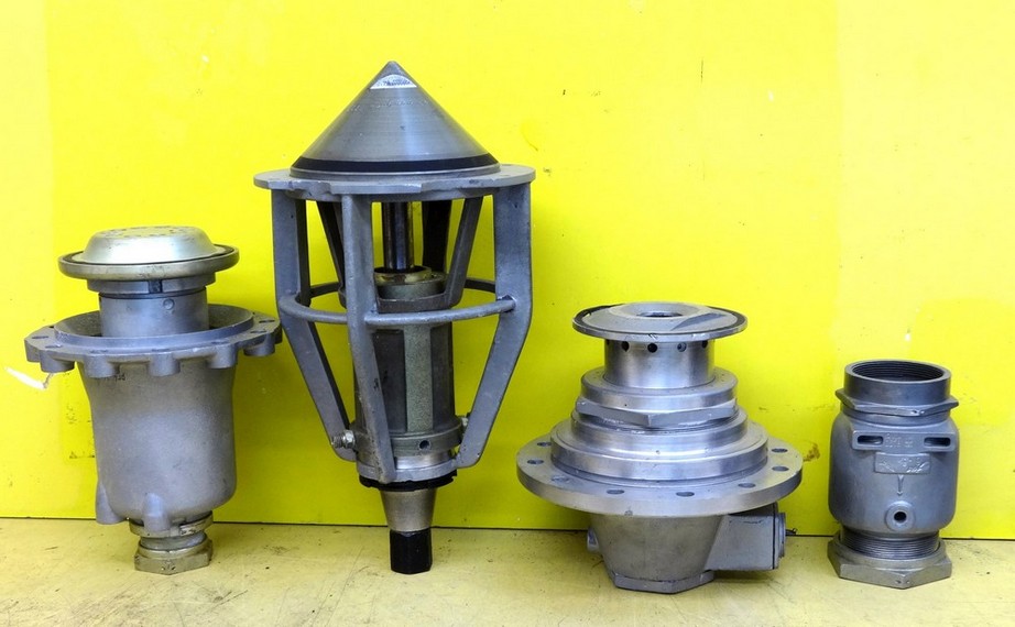
Images of the main valves involved in the propellant flow of the A4 / V2 liquid fuelled rocket engine
Relic of main alcohol valve with manufacturer code aeq (aeq = Bartoc & Co., Maschinenfabrik u. Giesserei Hedwikow,bei Caslau (Caslav) Czech Republic). An air (nitrogen) inlet pressure of 440 to 530 psi (30 to 36 Bar) was required to close this valve against its internal spring and the force of the turbo-pump. The large nut at the top is the connection for the fuel return (or ‘revolving’line) pipe, and the air and electrical input ports can be seen to the right (air), and left (elec.) just below this point. V2RH image

Anatomy of the V2: 18-pot injector head
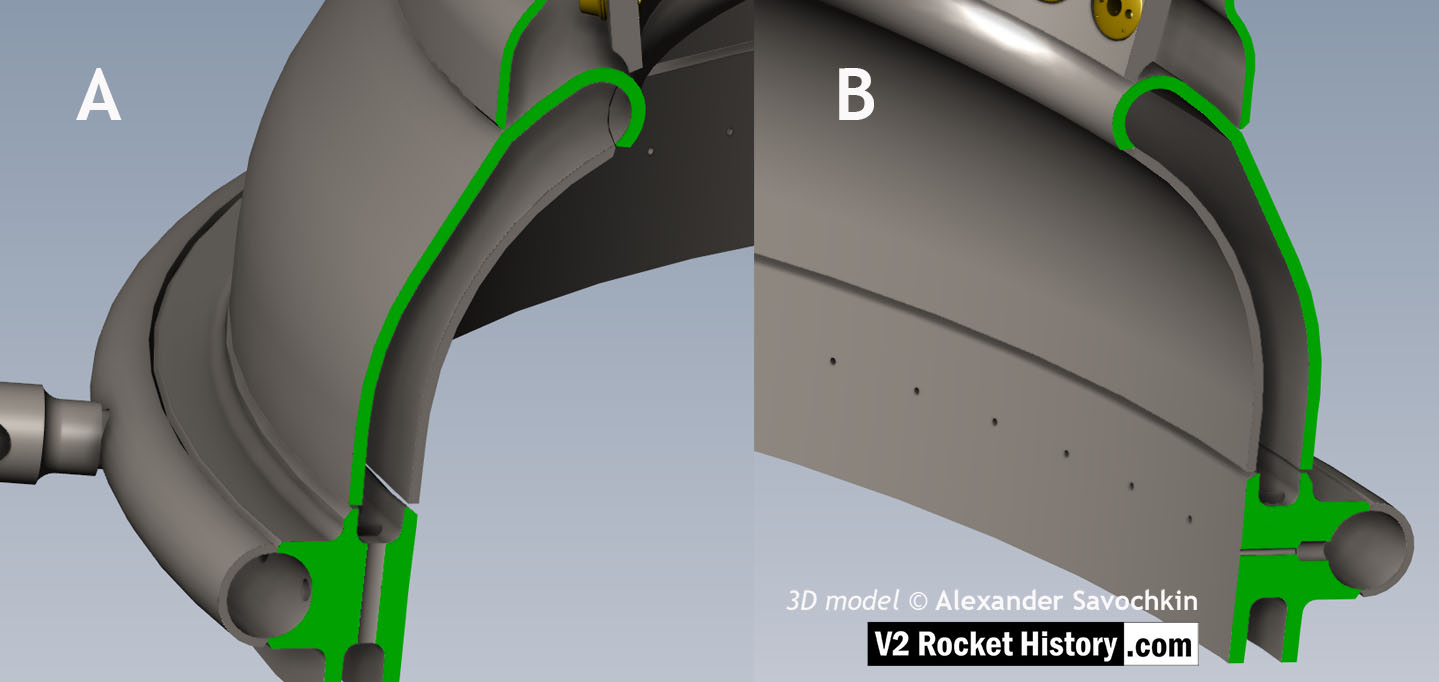
Close-up detail showing independent pathway for fuel passing into injector head and fuel passed down from the head to be used for veil cooling system. Fig. A shows vertical passages for overall fuel feed to the head and Fig.B shows horizontal pathway for veil coolant fed from the head via the veil coolant distributor ring or manifold. 3D model by Alexander Savochkin
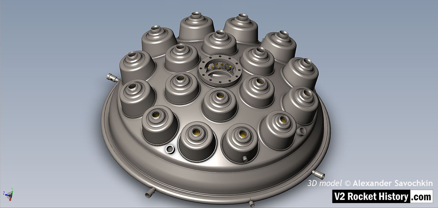
View of injector head showing 18 liquid propellant (LOX and fuel) diffuser cups and head fuel valve seating ring at centre, (see other images for insert and position nomenclature). Visible immediately below the valve seat are the large connecting holes that allow fuel to flow from the inlet manifold and cooling jacket to the injector space (some brass injector inserts can be seen through the holes) after the head fuel valve is released to be opened by the turbo-pump supply pressure. The four veil cooling inlet connectors are well shown as are two of the outlet connection holes immediately above them. 3D model by Alexander Savochkin
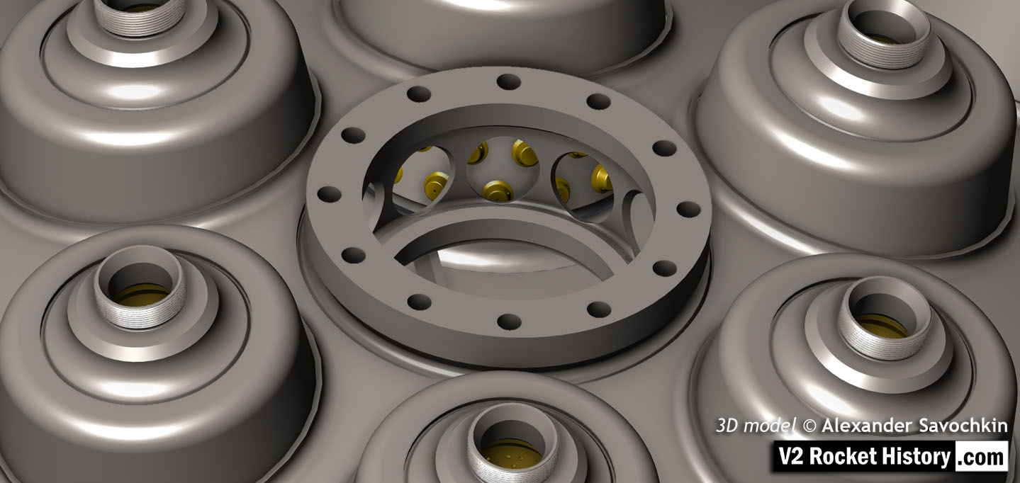
A close-up view of the head fuel valve mounting flange (showing 12 fastener holes). Visible immediately below the top flange are the large connecting holes that allow fuel to flow from the inlet manifold and cooling jacket to the injector space (some brass injector inserts can be seen through the holes) after the head fuel valve is released to be opened by the turbo-pump supply pressure.
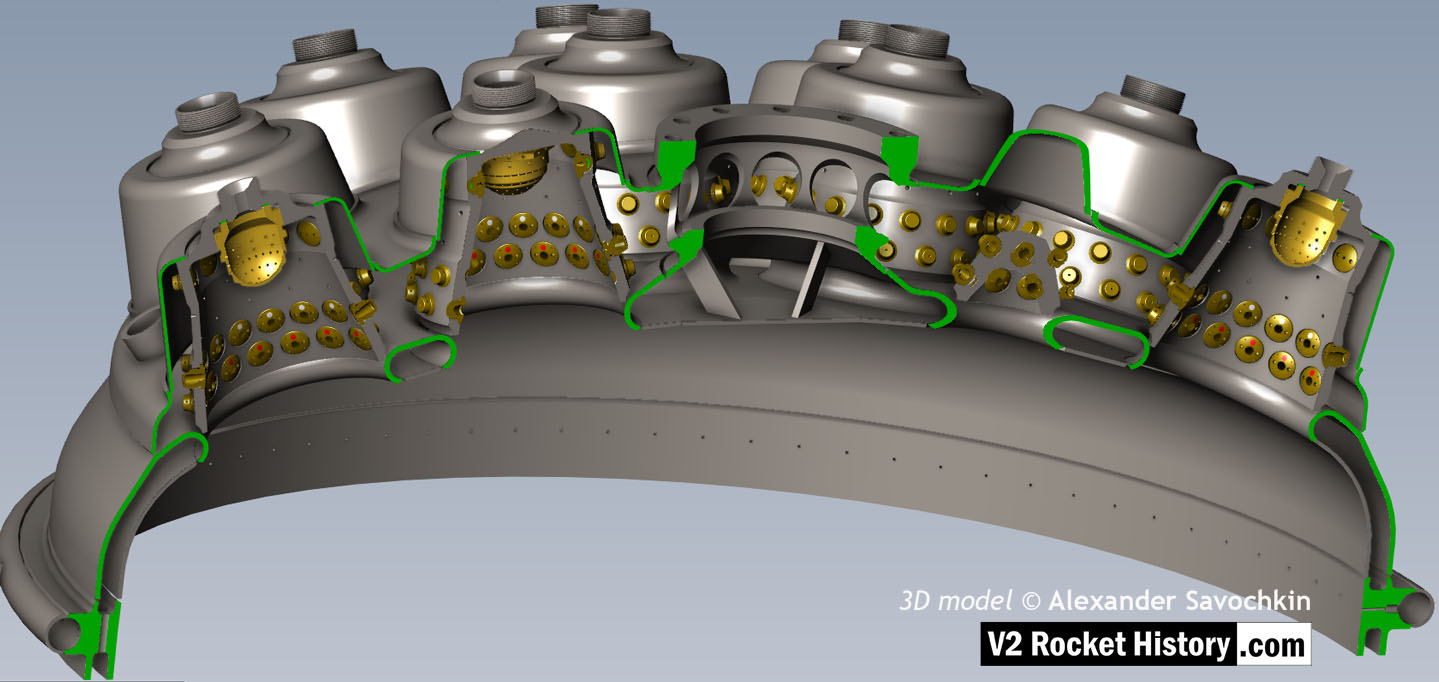
Here the 18-pot head model has been cutaway to show the fuel cooling and fuel delivery spaces. the cooling jacket layer can be seen in the lowermost area of the head – below the centrally positioned fuel valve seat, between each cup at the lowest point, and ruining down toward the first set of veil cooling pores and the topmost coolant distributor ring. Note that the veil cooling system does not communicate with the regenerative cooling jacket and has its own feed pipes drawing fuel from the head injector space and not the cooling space. Visible immediately above the valve seat are the large connecting holes that allow fuel to flow from the inlet manifold and cooling jacket to the injector space after the head fuel valve is released to be opened by the turbo-pump supply pressure. 3D model by Alexander Savochkin
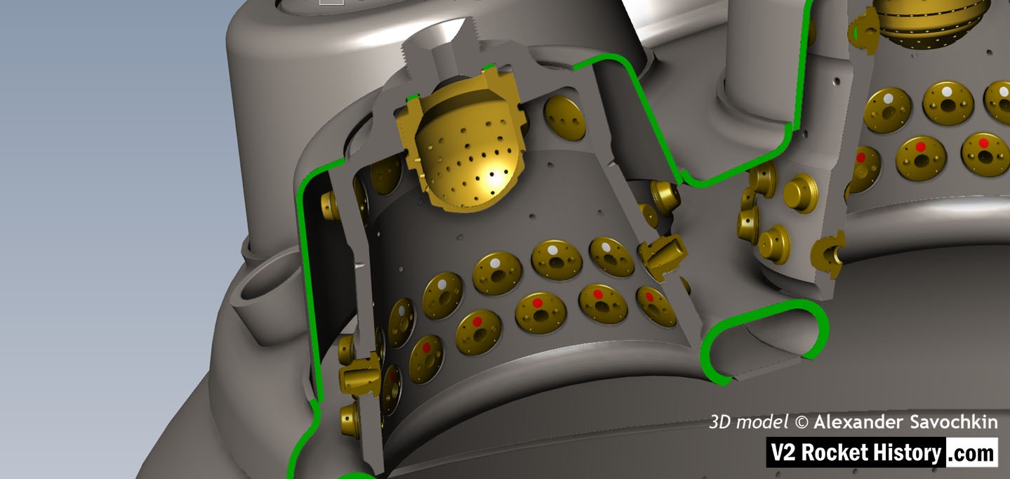
Liquid propellent (LOX and fuel) diffuser cup, showing three rings or echelons (A,D,& E) of brass injector inserts as well as two rows of drilled fuel feed holes. The LOX spray head is shown in the centre. Note the simple ‘shower head or watering can’ design of the LOX diffuser. A sealing washer can be seen fitted between the LOX diffuser and the steel cup. 3D model by Alexander Savochkin

Testing fuel injectors
Categories: Peenemünde-Usedom-locations, V2 Missile relics

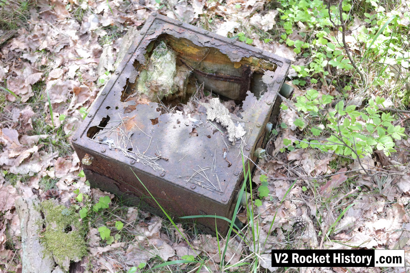
The photo shows a Lichtstrahl empfänger (In English: Light-beam receiver) environmental protection case, originally one of a group of 40 or so we first found in 2010 abandon in an area adjacent to the train platform for the administration block. On subsequent visits this number has declined to just ten or so, mostly very decayed examples. The environmental casing was vital to the Lorentz Light-Beam equipment on-board the V2 missile as the critical radio frequency would otherwise drift with the large change in temperature as the missile climbed into the stratosphere. The case was thickly insulated with rock wool or fibre-glass strands and designed to help maintain a stable temperature – indeed, the same temperature as the radio equipment was when at ground level when calibration and adjustment was completed before launch. The F1 pre-production hall is located about 200m North-West of the point where this photo was taken. Scroll down to see map below (click map and switch to ‘satellite view’ for clearer indication of location).

