Archives: Gmedia Albums


Turbopump 3D CAD
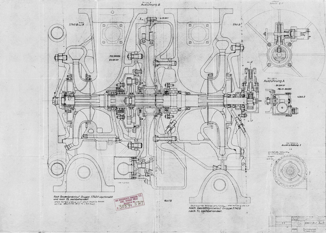
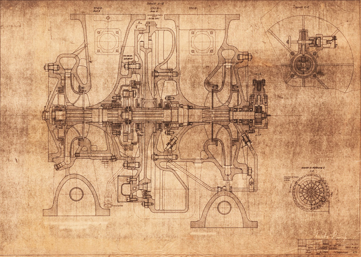
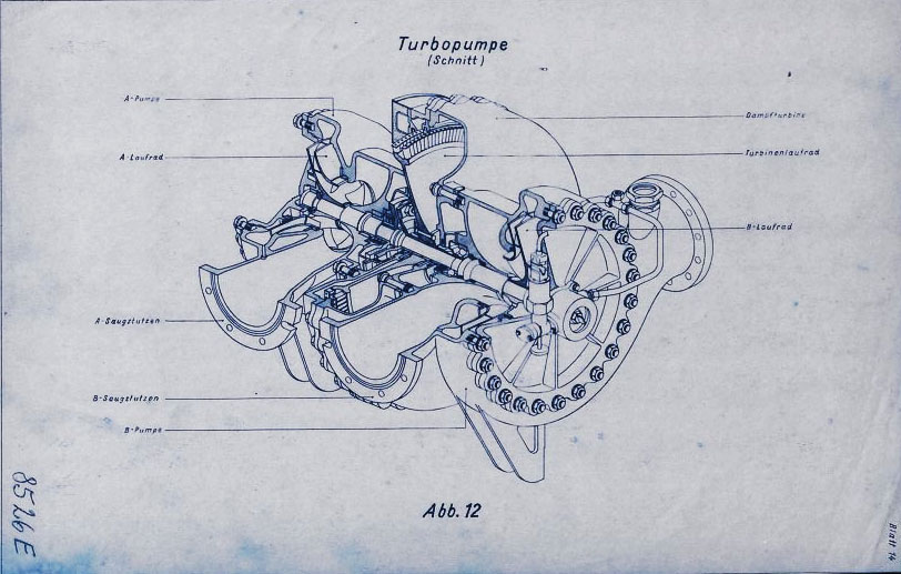
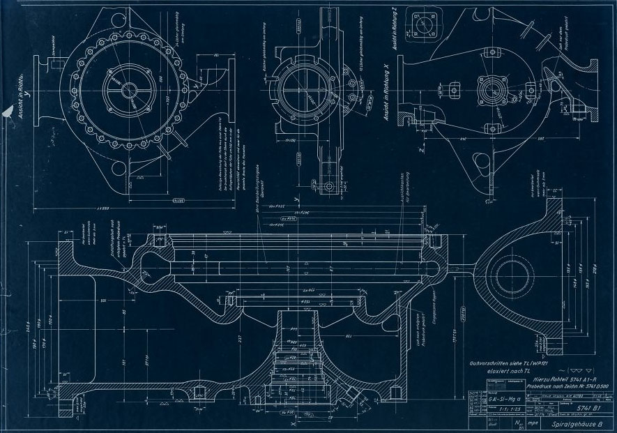
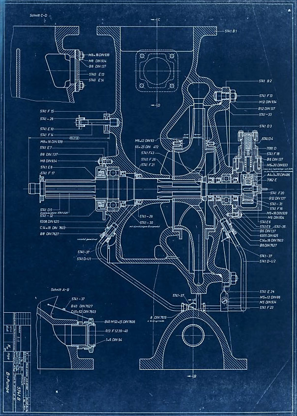
3D CAD model images of the A4/V2 rocket engine’s steam turbine powered propellent pumps – all images by Ray Matter. To see Ray Matter’s blog 3D CAD modelling the V2 rocket turbopump introducing these images, just click the link.
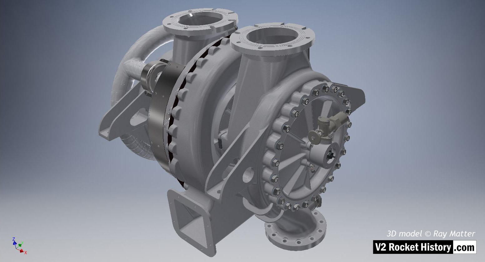
Turbine powered propellant pumps for A4/V2 rocket engine – fuel pump on right. Full perspective assembly showing tubular ring steam inlet manifold with asbestos bandage extreme left, inlet flanges at top, frame support brackets, steam exhaust outlet square shape lower center. The overspeed trip switch can be seen just above center on fuel pump face plate. The fuel outlet flange can also been seen btm right of center. 3D model by Ray Matter
| Album | Turbopump 3D CAD |
| Category | Turbo-pump |
Turbine powered propellant pumps for A4/V2 rocket engine – fuel pump on right. Full assembly showing steam inlet manifold on left, inlet flanges at top, support brackets, steam exhaust outlet square shape lower center. The over-speed trip switch can be seen just above center on fuel pump face plate. The fuel outlet flange can also been seen btm right of center. 3D model by Ray Matter
| Album | Turbopump 3D CAD |
| Category | Turbo-pump |
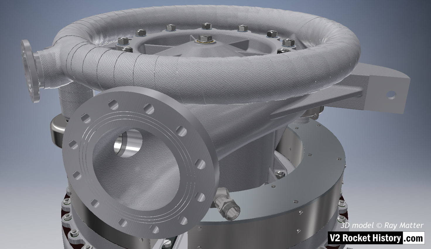
Full assembly showing, from top, steam inlet ring manifold, LOX pump and portion of steam turbine assembly. View shows outlet flange facing camera. Note the three fine rings milled into flange face. The rings were designed to improve keying for the sealing ‘putty’ that was used to seal the connection between the flange face and the inlet pipe. 3D model Ray Matter
| Album | Turbopump 3D CAD |
| Category | Turbo-pump |
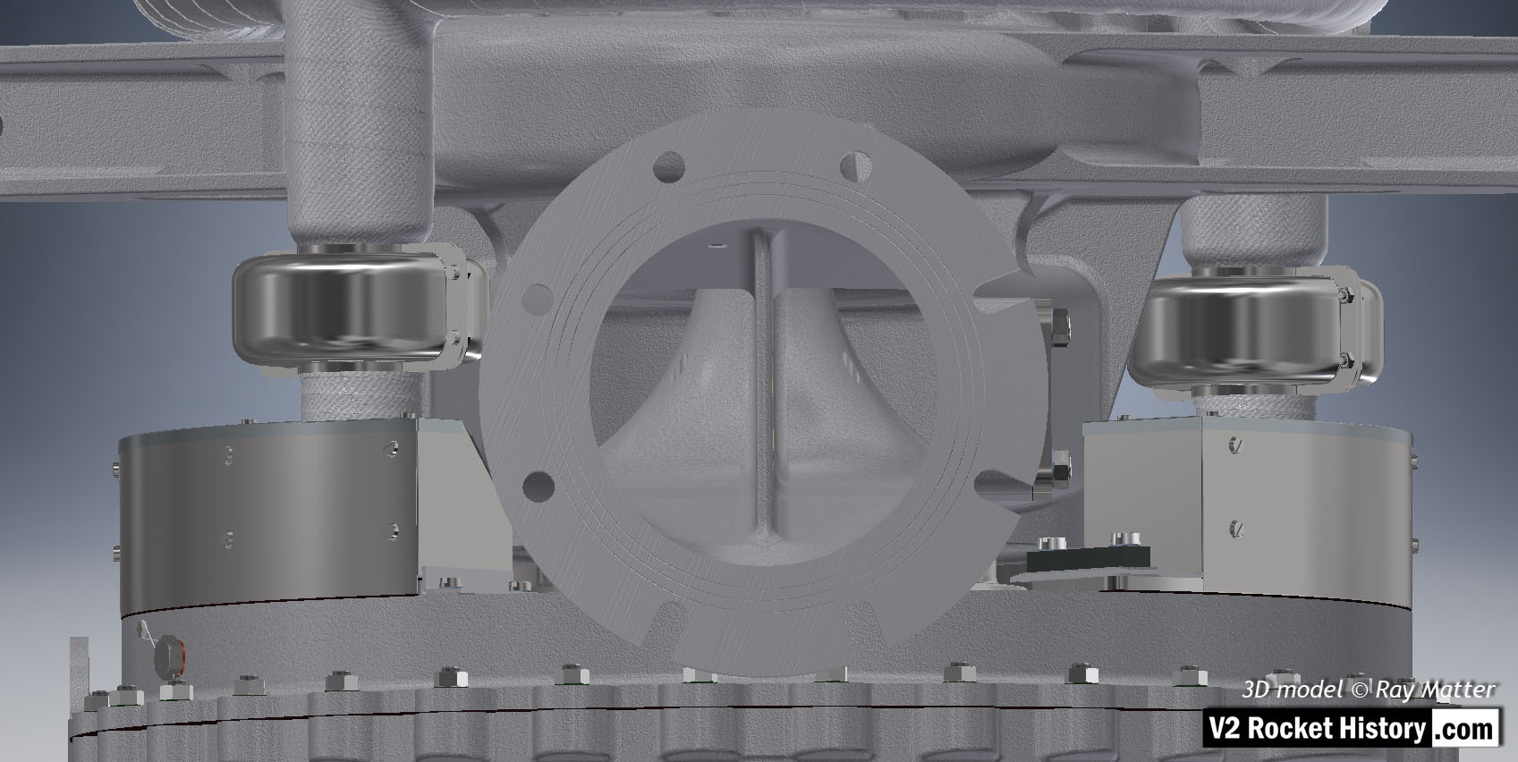
A (LOX) Pump close-up showing inlet flange, with fastener slots and holes, as well as the throat baffle. To the right and left of the flange, the steam inlets are shown – with steel cases covering the steam manifold connection flanges. Of special note in this view is the self-purge orifice seen at the top right-hand side of the inlet throat baffle. This hole allowed gas to escape from the top of the LOX volute space back to the low-pressure inlet throat and proved problematic in manufacturing and was revised in late 1944. 3D model Ray Matter
| Album | Turbopump 3D CAD |
| Category | Turbo-pump |
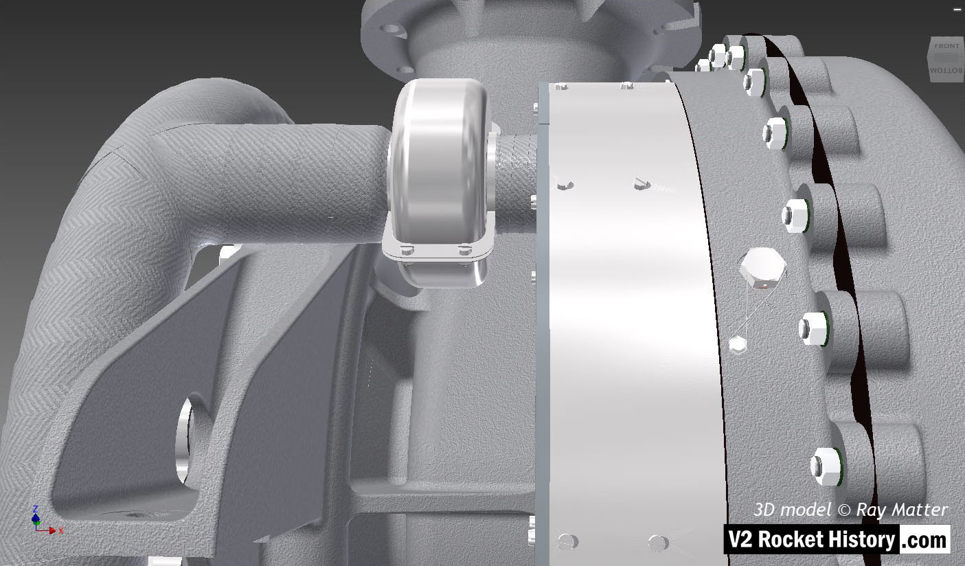
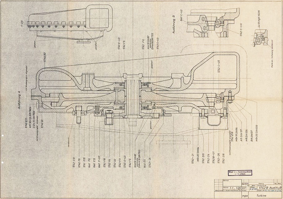
Close-up of turbine steam inlet ring manifold showing one of the entry points. The thin steel case that fits around the steam manifold mating flanges is clearly shown as is the wire restraint fastener locking system (see close-up in gallery). 3D model by Ray Matter
| Album | Turbopump 3D CAD |
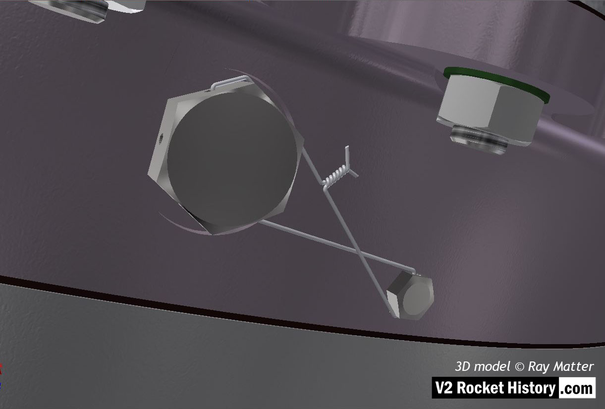
Turbine powered propellant pumps for A4/V2 rocket engine – close-up of turbine casing shows wire restraint fastener locking system. 3D model by Ray Matter
| Album | Turbopump 3D CAD |
| Category | Turbo-pump |
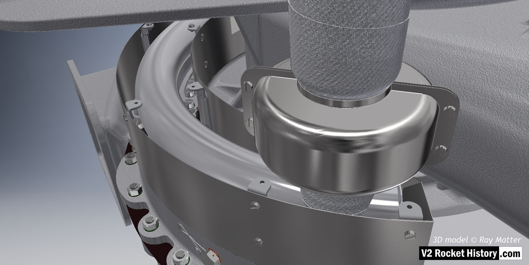
Close-up of turbine showing steel case with lid removed to show steam inlet ring manifold. The thin steel case that fits around the steam manifold mating flanges is clearly shown as is the wire restraint fastener locking system (see close-up in gallery). 3D model by Ray Matter
| Album | Turbopump 3D CAD |
| Category | Turbo-pump |
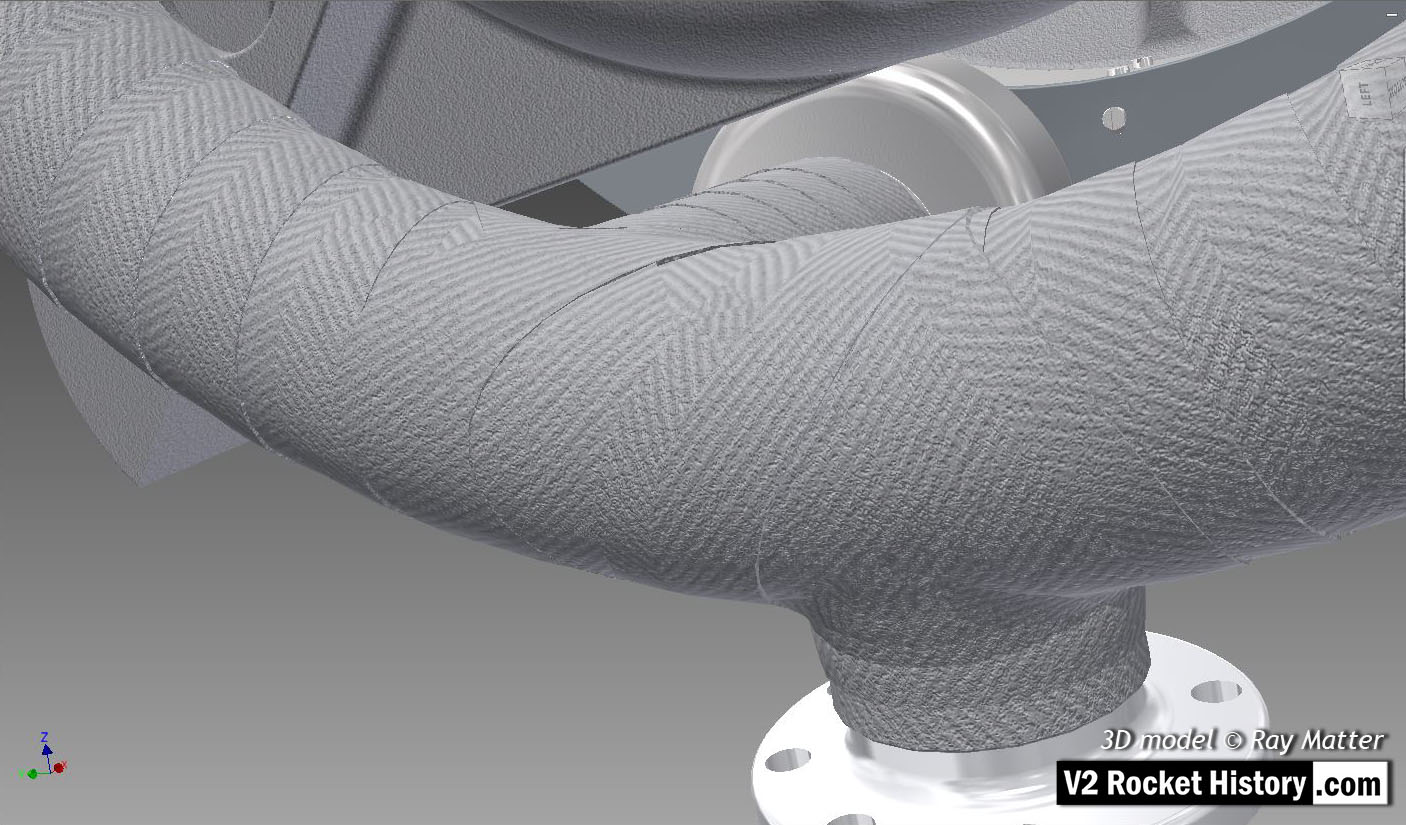
Close-up of turbine steam inlet ring manifold showing asbestos bandage wrapped around the tubular ring. Sometimes a thin wire was used to help retail the heat resistant material. This bandage is often missing from museum exhibits. 3D model by Ray Matter
| Album | Turbopump 3D CAD |
| Category | Turbo-pump |
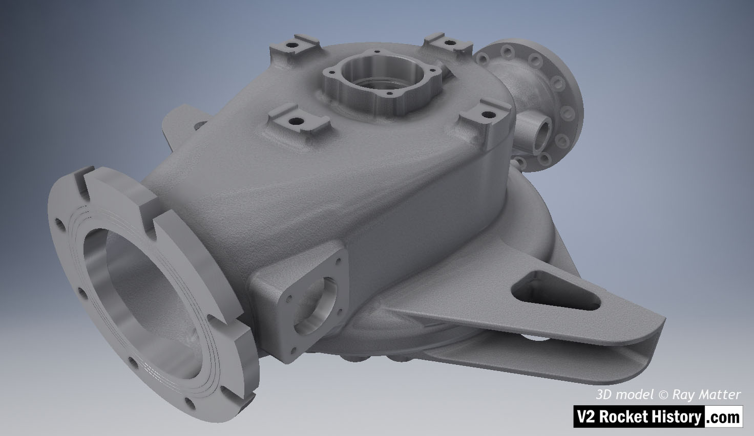
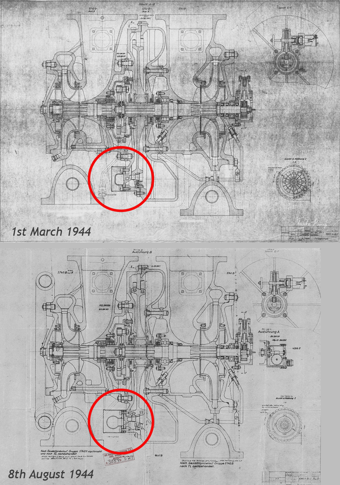
B (fuel) Pump sub-assembly, single piece casting showing machined (milled) areas without fittings. View shows inlet flange fastener slots and the throat aperture – facing right, initially blanked off by square plate, but towards the end of 1944 used for fuel return from the main fuel valve situated in the center of the thrust chamber injection head. 3D model Ray Matter
| Album | Turbopump 3D CAD |
| Category | Turbo-pump |
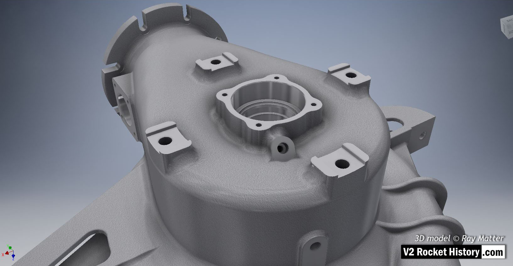
B (fuel) Pump sub-assembly, single piece casting showing machined (milled) areas and without fittings. 3D model Ray Matter
| Album | Turbopump 3D CAD |
| Category | Turbo-pump |
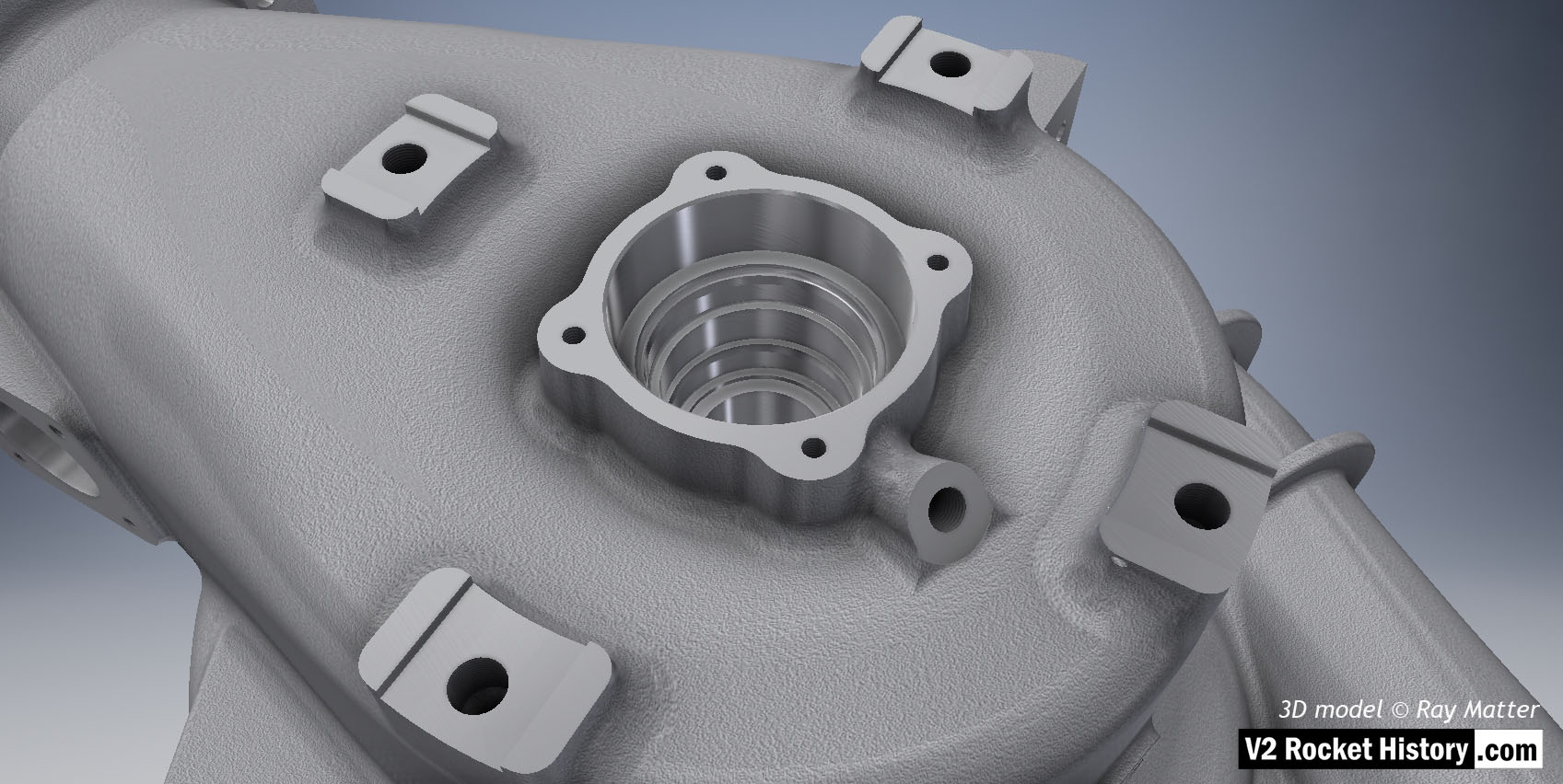
B (fuel) Pump sub-assembly shown without fittings. Single piece casting showing detail of bearing and seal cavity as well as threaded fuel bleed connection. 3D model Ray Matter
| Album | Turbopump 3D CAD |
| Category | Turbo-pump |
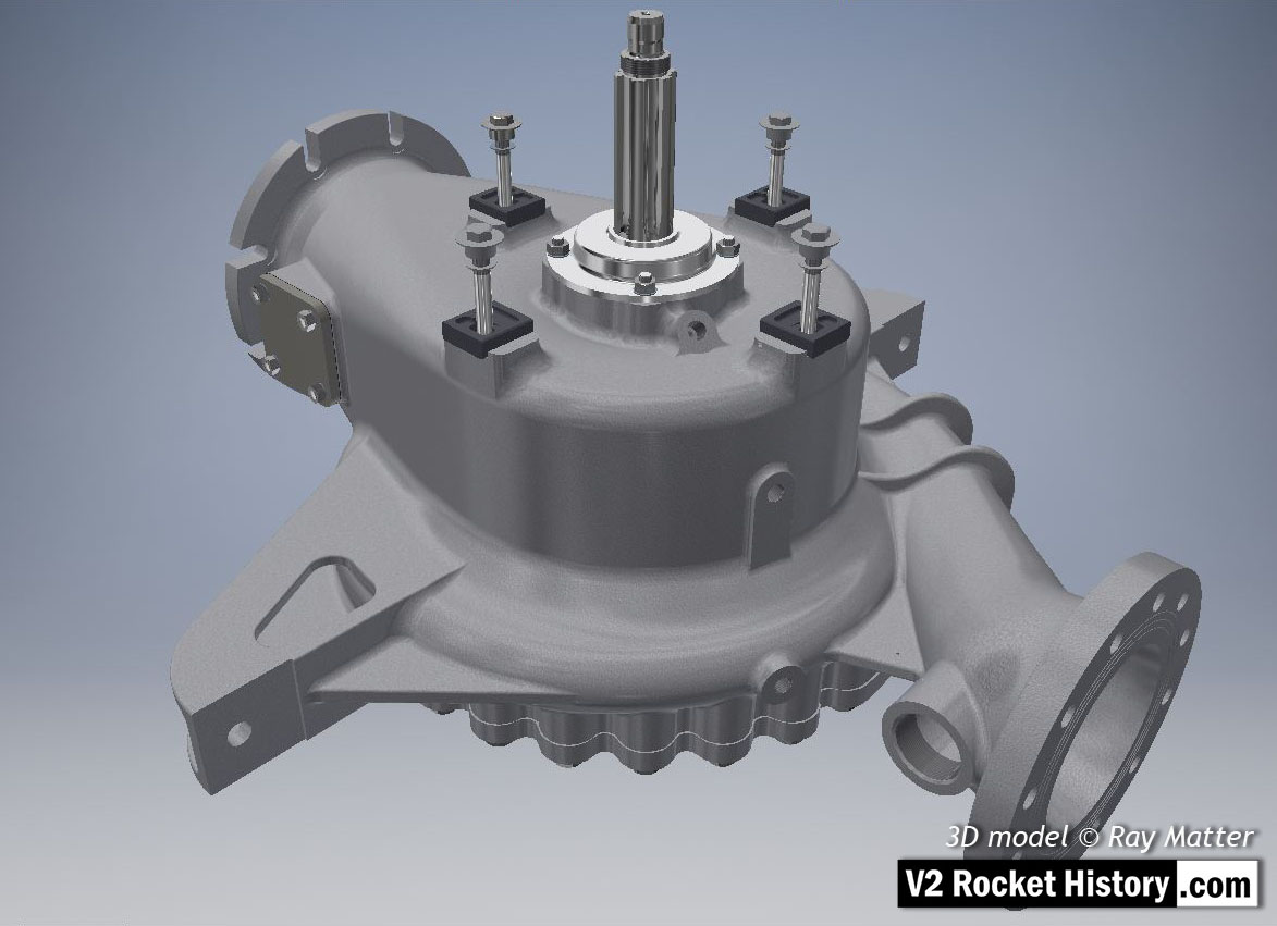
B-Pump sub-assembly, showing earlier version square inlet throat blanking plate (later versions employed a fuel return connection point mounted on this plate).
Fastenings, turbine case contact furniture, splined turbine connection shaft, and shaft seal cap are also shown. 3D model Ray Matter
| Album | Turbopump 3D CAD |
| Category | Turbo-pump |
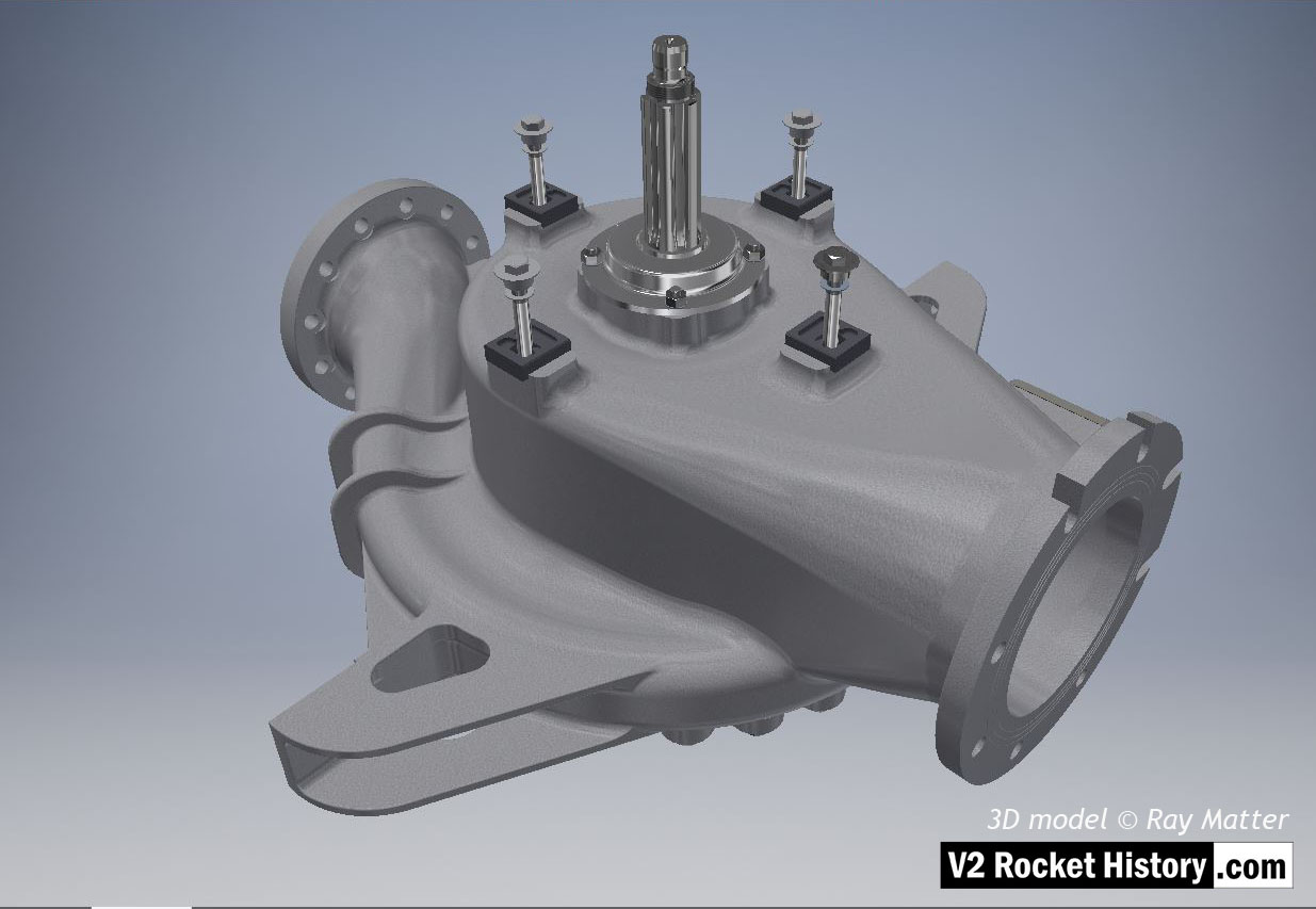
B-Pump sub-assembly complete with fastenings, turbine case contact furniture, splined turbine connection shaft, and shaft seal cap. 3D model Ray Matter
| Album | Turbopump 3D CAD |
| Category | Turbo-pump |
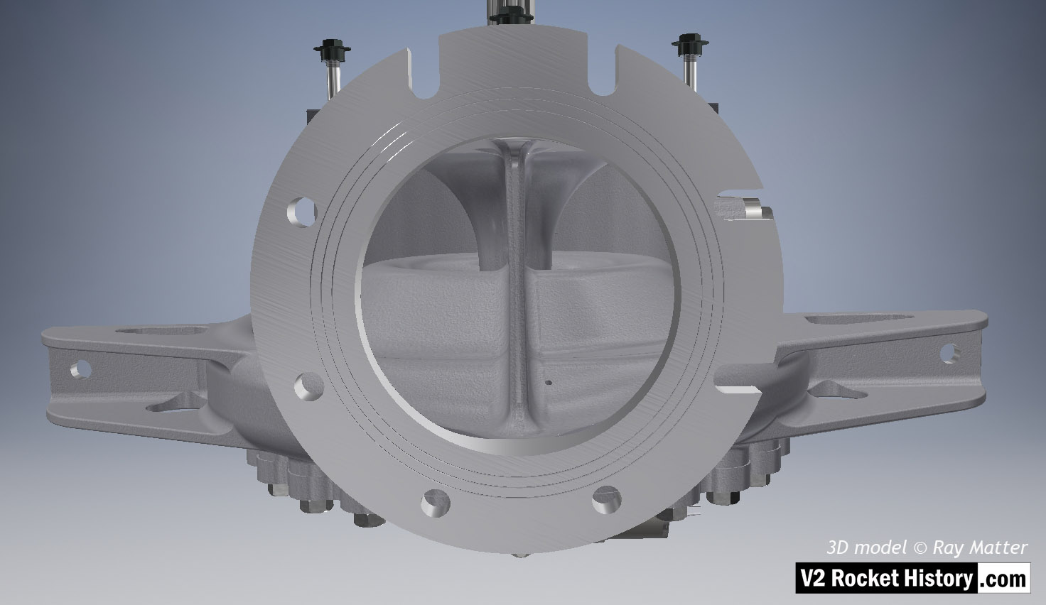
B-Pump Sub-assembly shown from top. View shows outlet flange facing camera – the splined drive shaft can just be seen at the top of the screen. Note the three fine rings milled into flange face.The rings were designed to improve keying for the ‘putty’ that was used to seal the connection between the flange face and the inlet pipe. Note, small self-purge orifice on the lower left of the inlet throat baffle. Unlike the upper purge hole in the LOX casing, the shallower face angle at the location of the hole in the fuel pump casing, was more accessible to drilling and was therefore not problematic. 3D model Ray Matter
| Album | Turbopump 3D CAD |
| Category | Turbo-pump |
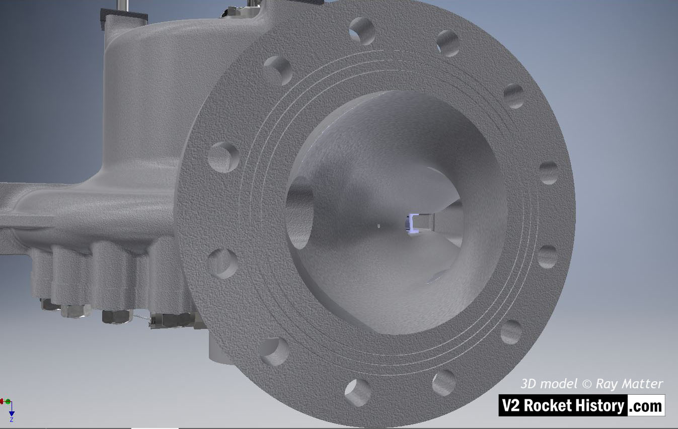
B-Pump sub-assembly close-up showing fuel outlet flange. Note the three fine rings milled into the flange face. The rings were designed to improve keying for the ‘putty’ that was used to seal the connection between the flange face and the flow choke. Both faces of the choke and top face of the fuel outflow connector had similar rings. 3D model Ray Matter
| Album | Turbopump 3D CAD |
| Category | Turbo-pump |
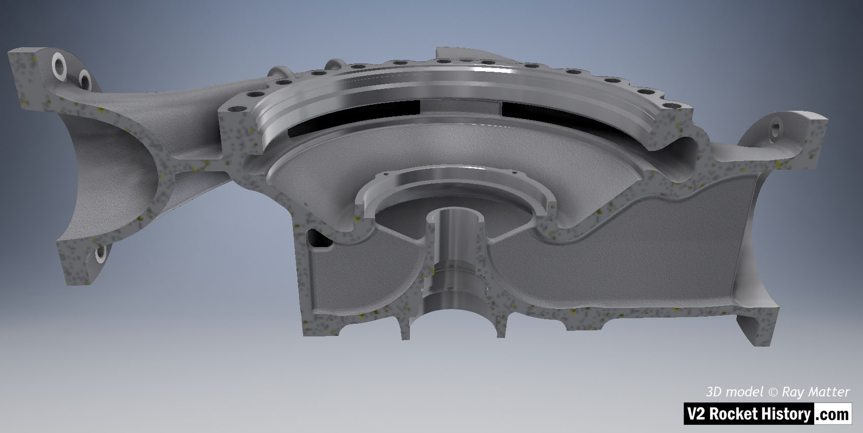
B Pump housing sectioned to show baffle and volute space area expansion as flow passes from inlet (right) to outlet (left). 3D model Ray Matter
| Album | Turbopump 3D CAD |
| Category | Turbo-pump |
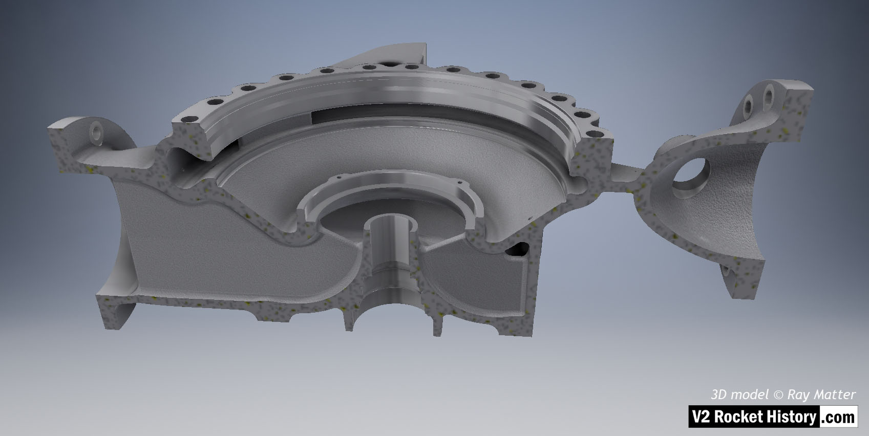
B Pump housing sectioned to show baffle with vent and volute space area expansion as flow passes from inlet (left) to outlet (right). 3D model Ray Matter
| Album | Turbopump 3D CAD |
| Category | Turbo-pump |
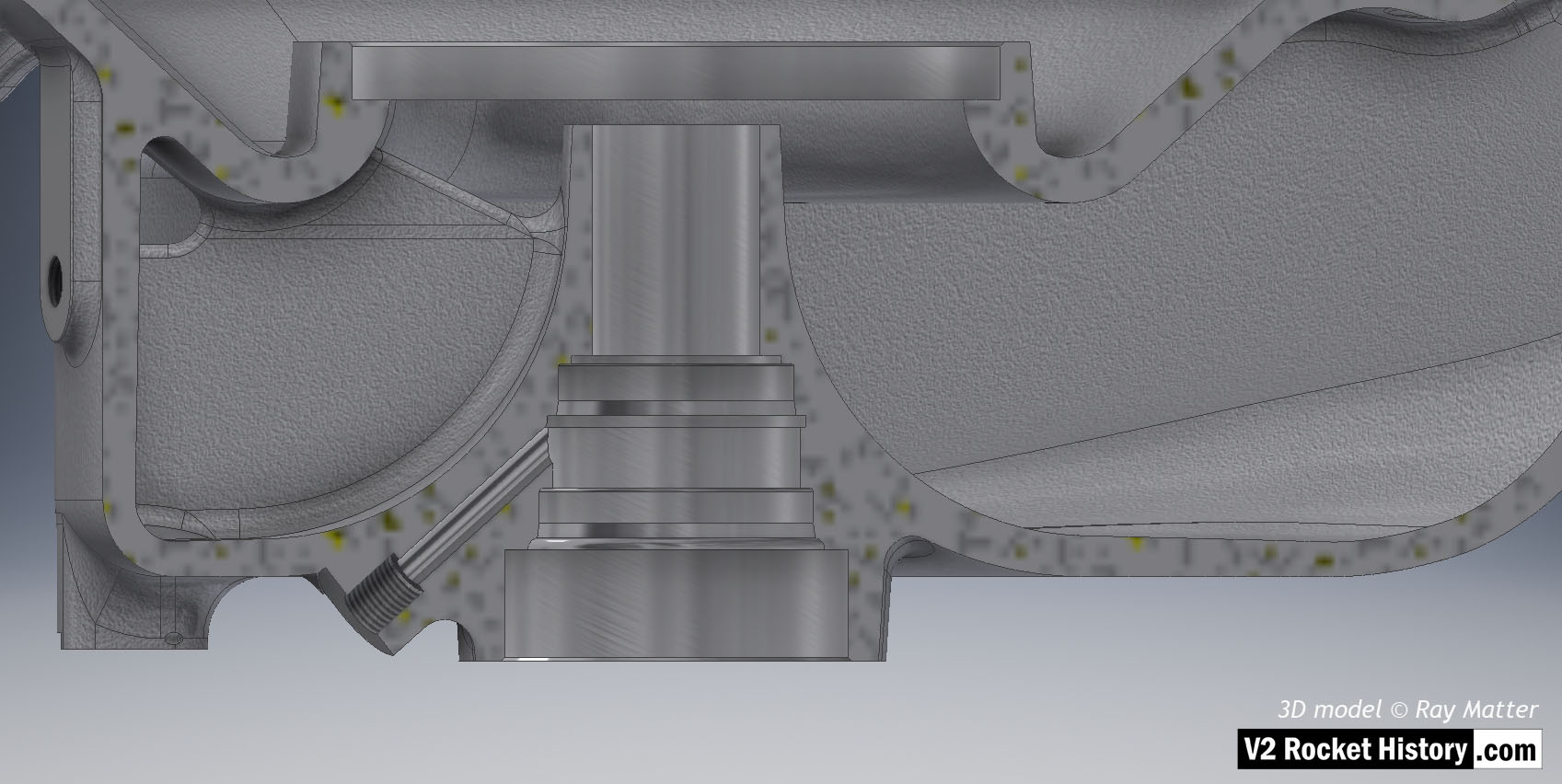
B pump housing showing sectioned area for shaft and bearing cavities with fuel pathway to left. 3D model Ray Matter
| Album | Turbopump 3D CAD |
| Category | Turbo-pump |
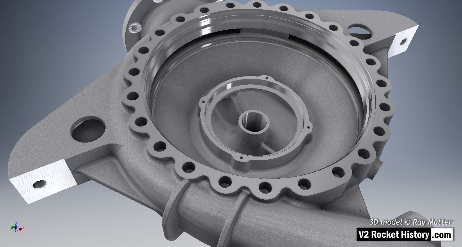
‘B’ fuel pump housing for V2 rocket engine turbopump showing cast and machined surfaces – some machined areas with obvious specular reflections. Of note are the rarely seen machined contact points on the integral support brackets and the larger areas in two locations in the ring of double ended bolt fixing holes seen at 12 and 6 o’clock. These areas allowed two ‘push’ screws to be threaded into corresponding locations in the face plate. These could then be screwed down to provide a pushing force to remove the face plate from the main housing seat. This retraction system was required owing to the very tight fit of the face plate due to the narrow ‘piston fit’ tolerances and the vacuum effect of a soft gasket that was employed between the faces. 3D model by Ray Matter
| Album | Turbopump 3D CAD |
| Category | Turbo-pump |
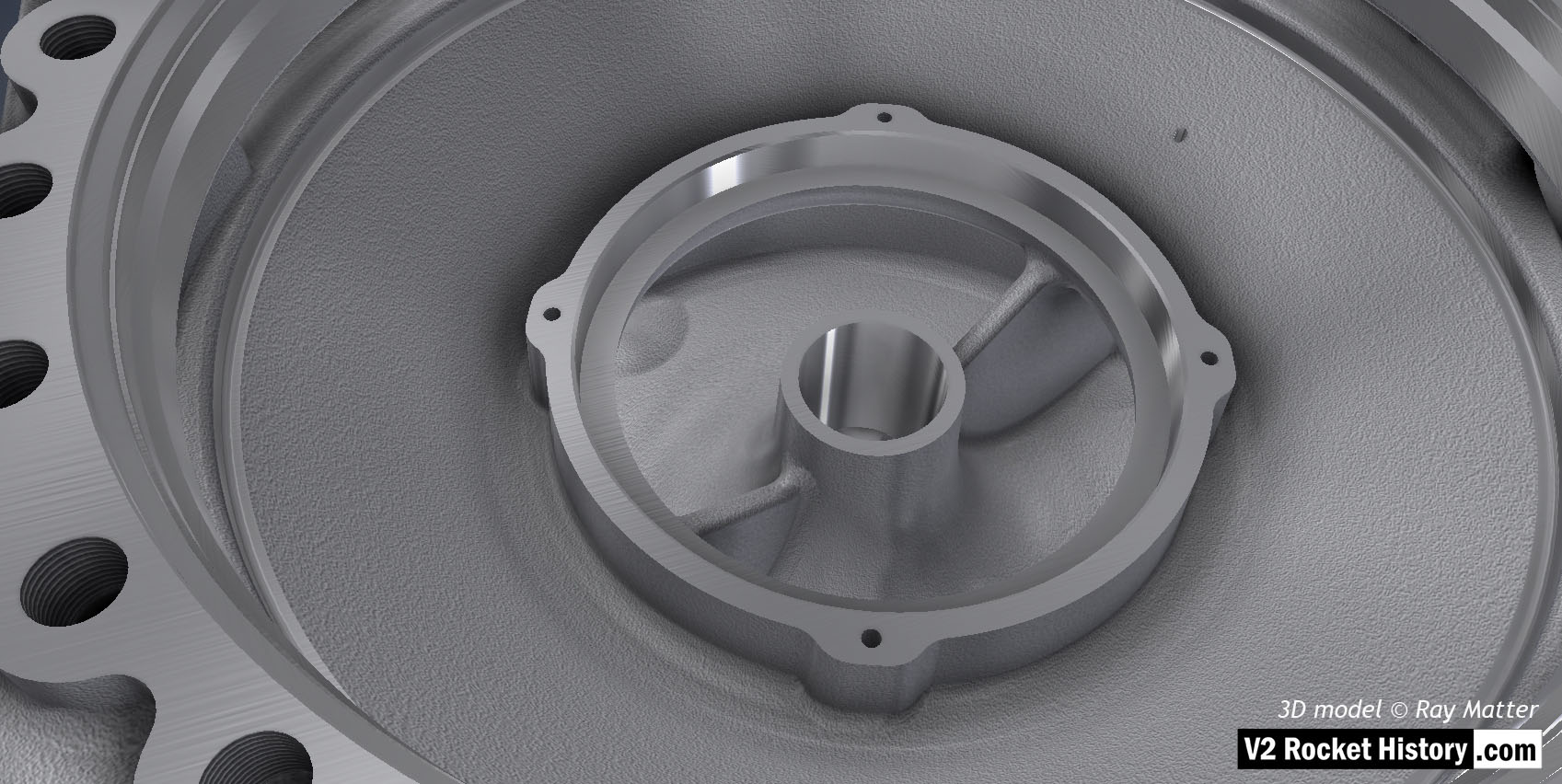
Close-up of ‘B’ fuel pump housing displaying cast and machined surfaces. Fuel inlet aperture shown with small purge orifice shown at 2 o’clock. 3D model by Ray Matter
| Album | Turbopump 3D CAD |
| Category | Turbo-pump |
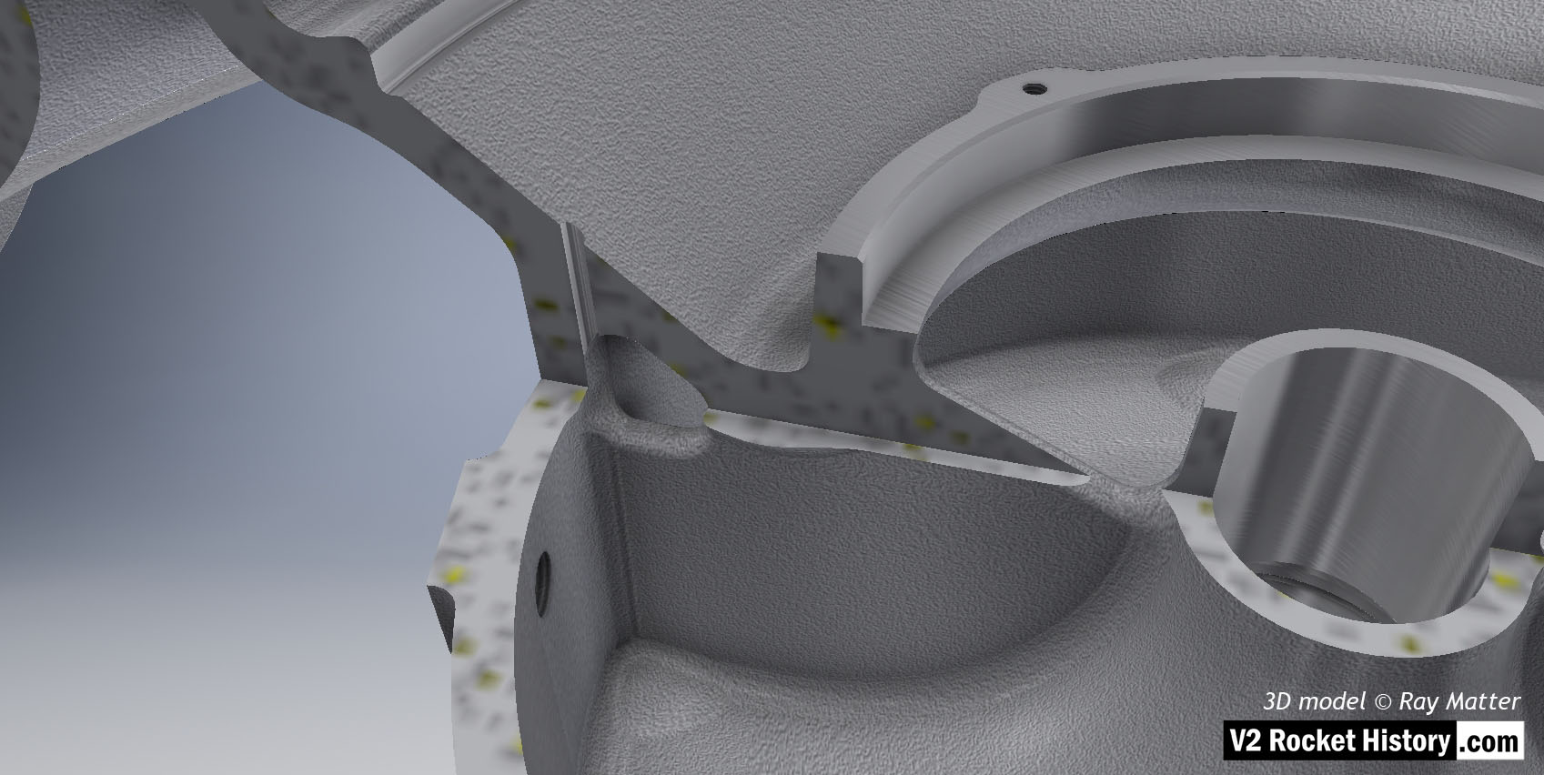
B Pump Housing, sectioned to show close-up of fuel bleed aperture and baffle vent for fuel pressure equalization between cavities inside the B pump casing. 3D model by Ray Matter
| Album | Turbopump 3D CAD |
| Category | Turbo-pump |
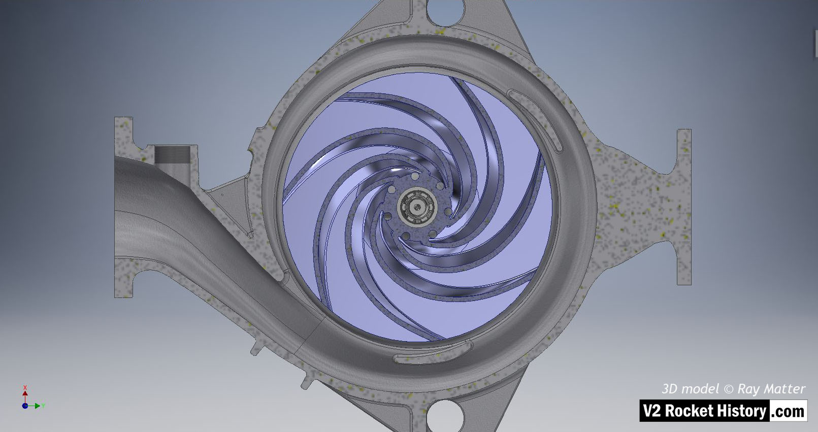
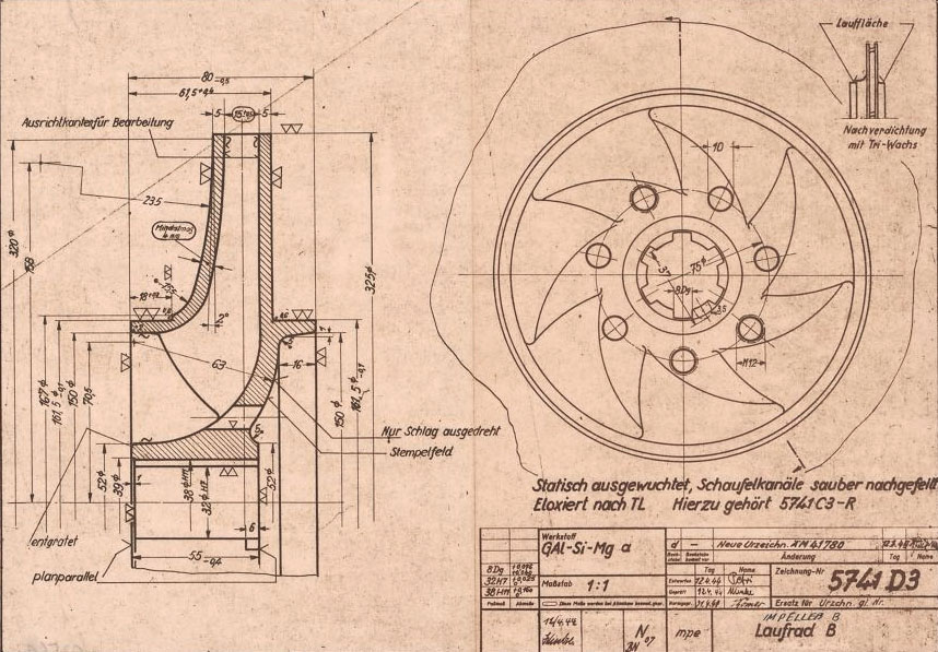
B (fuel) pump sub-assembly elevation view showing sectioned casing to reveal centrifugal pump impeller (in light purple for visibility). Outlet to left. The centrifugal pump impeller has been sectioned to remove one impeller face and reveal the curved vanes. The hub pass holes and end view of splined shaft are also shown. The spiral volute shape is very clear in this image. 3D model Ray Matter
| Album | Turbopump 3D CAD |
| Category | Turbo-pump |
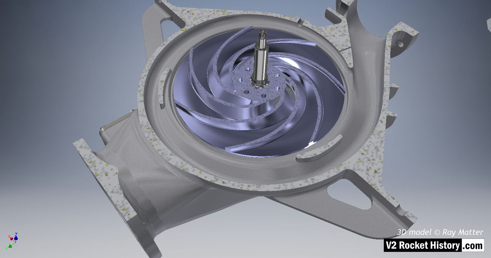
B (fuel) pump sub-assembly showing sectioned casing to reveal centrifugal pump impeller (in light purple for visibility). Outlet to top right. The centrifugal pump rotor has been sectioned to remove one impeller face and reveal the curved vanes.The shaft and spiral volute space shape is very clear in this image. 3D model Ray Matter
| Album | Turbopump 3D CAD |
| Category | Turbo-pump |
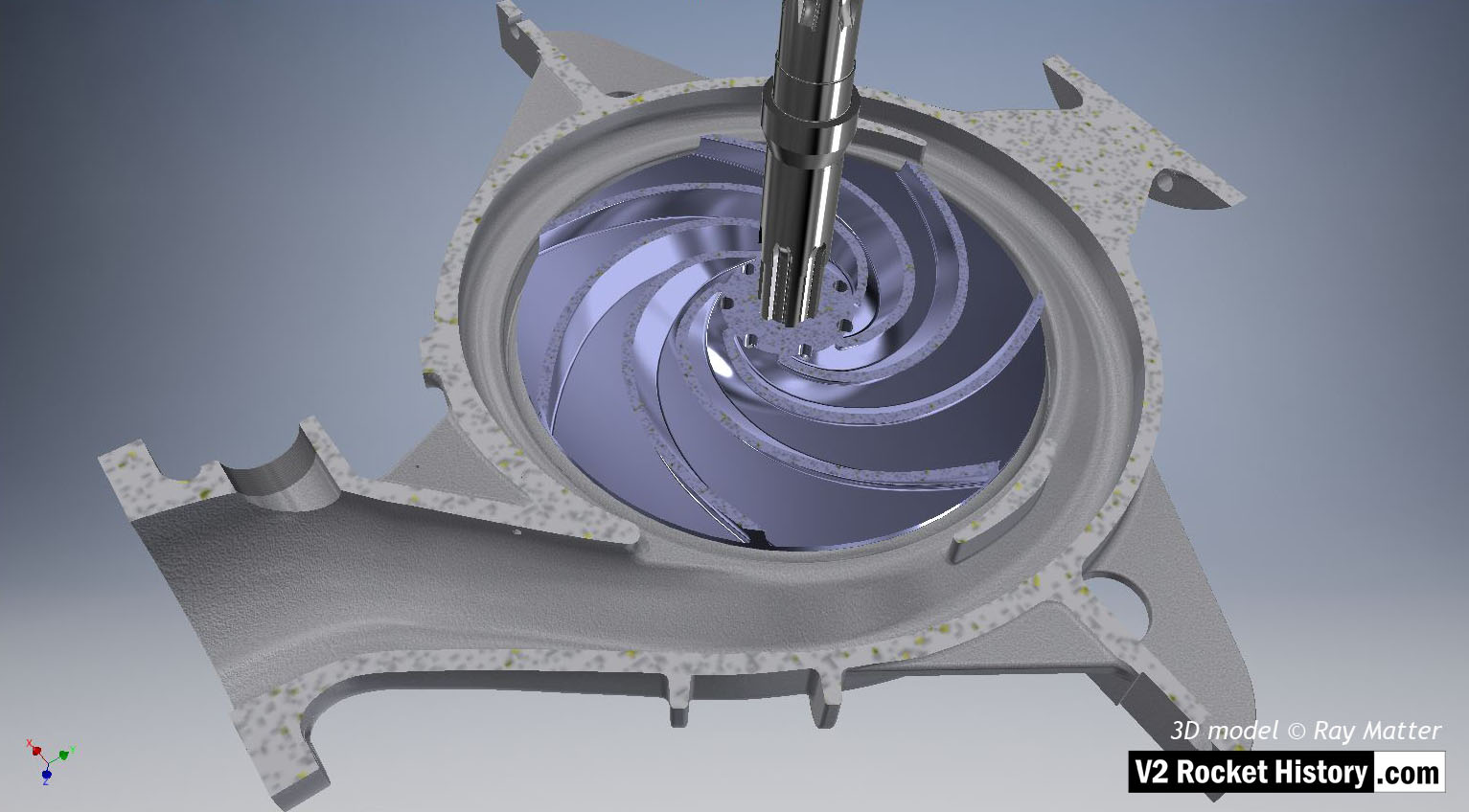
B (fuel) pump sub-assembly showing sectioned casing to reveal centrifugal pump impeller. Outlet to btm right. The centrifugal pump impeller has been sectioned to remove one rotor face and reveal the curved vanes. The shaft and spiral volute space shape are shown in this image. 3D model Ray Matter
| Album | Turbopump 3D CAD |
| Category | Turbo-pump |
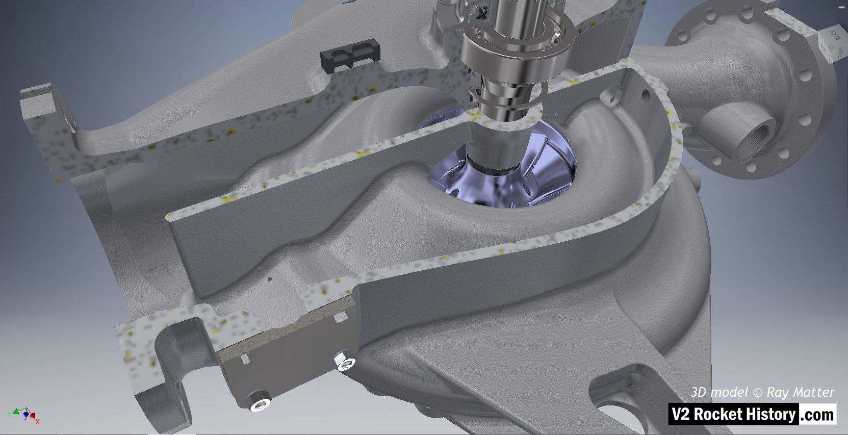
B-Pump sub-assembly sectioned to show fuel pump impeller inlet (purple area), baffle, and other shaft details. 3D model Ray Matter
| Album | Turbopump 3D CAD |
| Category | Turbo-pump |
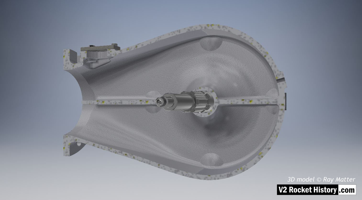
B-Pump sub-assembly casing sectioned to show shaft and fuel inlet chamber details. The throat blanking plate can be seen top left. 3D model Ray Matter
| Album | Turbopump 3D CAD |
| Category | Turbo-pump |
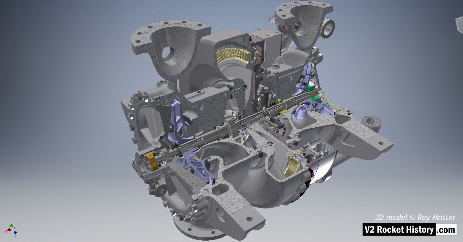
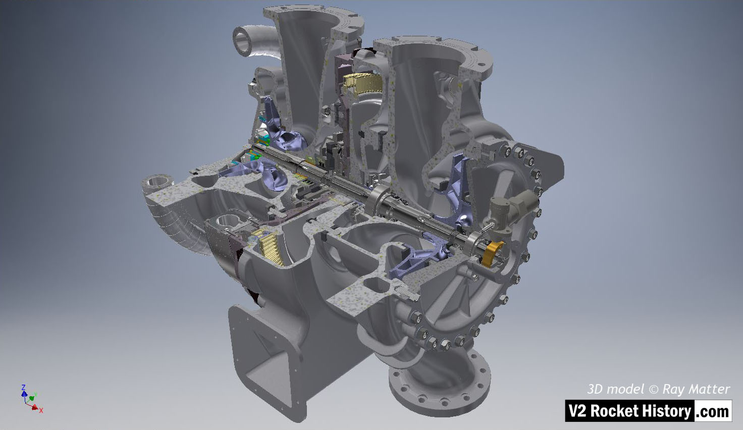
Turbine powered propellant pumps for A4/V2 rocket engine. The assembly is shown quarter sectioned and inverted with the propellant outlet flanges to the top and fuel pump on left, with inlet flanges at btm. The overspeed trip switch can be seen just below center on fuel pump face plate – the copper alloy centrifugal trip rotor is clearly visible in the trip-switch housing. 3D model by Ray Matter
| Album | Turbopump 3D CAD |
| Category | Turbo-pump |
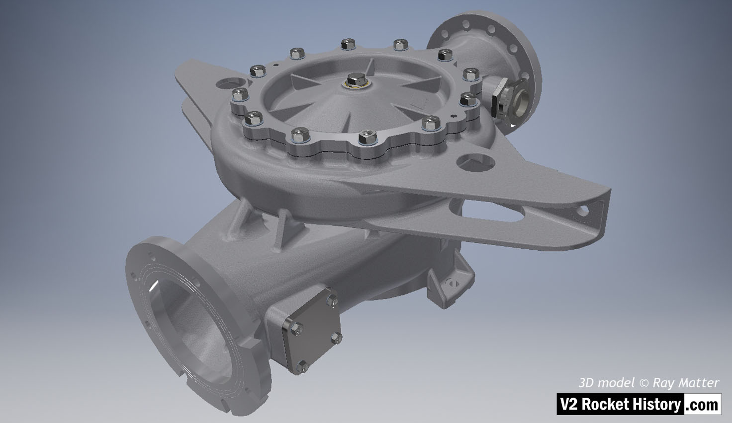
A-Pump LOX sub-assembly complete with face plate and fastenings as well as outlet throat plug. Shows square inlet throat blanking plate.
3D model Ray Matter
| Album | Turbopump 3D CAD |
| Category | Turbo-pump |
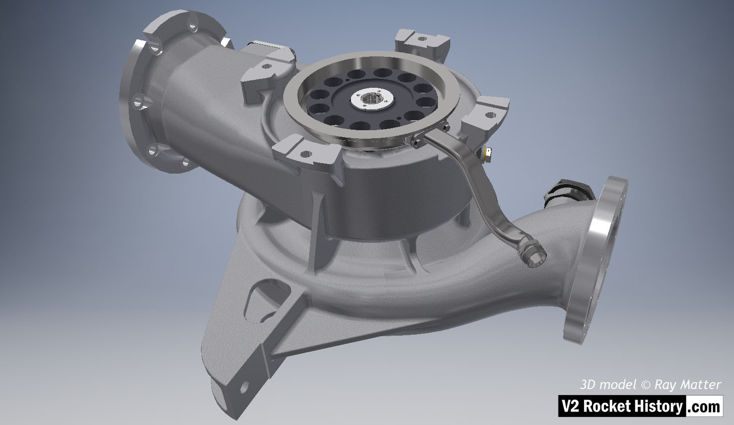
A (LOX) Pump sub-assembly, showing the face nearest the steam turbine. Turbine side of LOX pump showing flexible shaft connection disk (back component with 12 holes). The connection cavity drain pipe is shown (running across the outflow to the btm right). 3D model Ray Matter
| Album | Turbopump 3D CAD |
| Category | Turbo-pump |
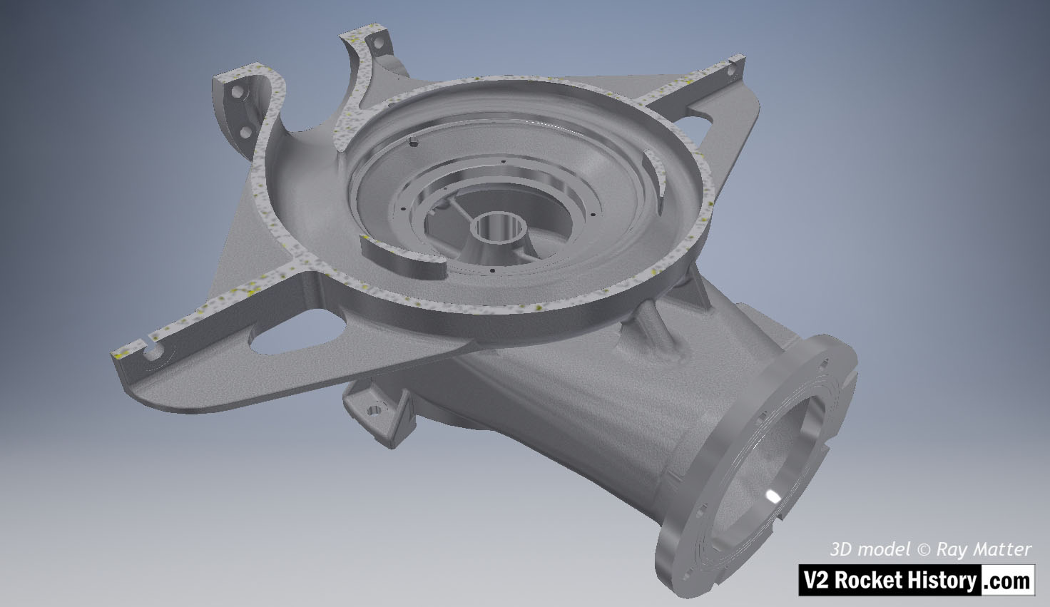
A (LOX) pump housing cutaway to reveal pump rotor side. The casing has been cut to show the internal rotor space detail. The outlet throat, right, and spiral volute space are displayed in this view as is the central LOX inlet. The web with the self-purge passageway can be seen on the outside center of the inlet throat, and connecting to the volute casing. The web or buttress seen to the upper right is to provide additional support between the structures whilst keeping the casting to an even density. 3D model Ray Matter
| Album | Turbopump 3D CAD |
| Category | Turbo-pump |
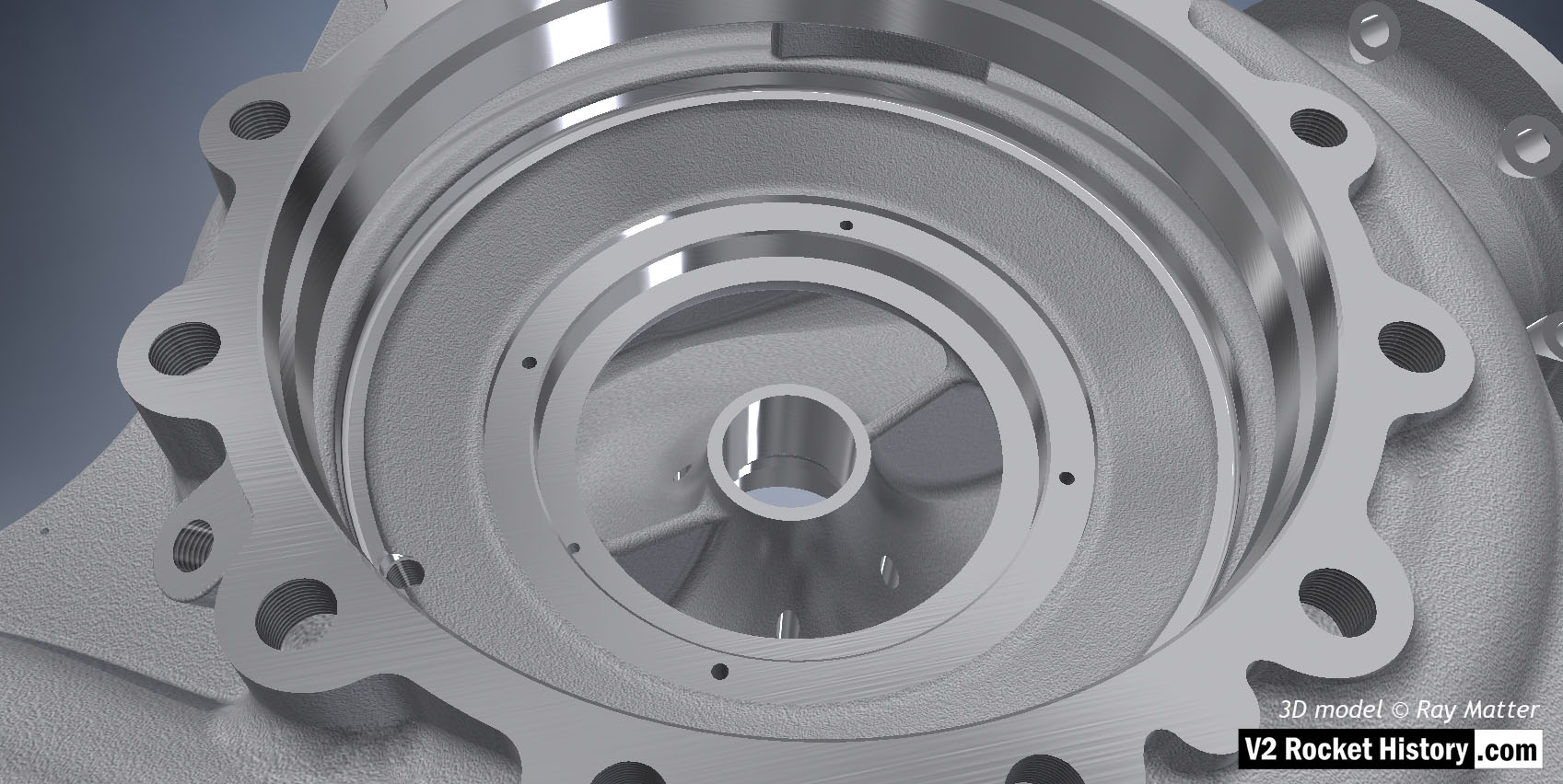
Close-up of ‘A’ LOX pump housing displaying cast and machined surfaces. LOX inlet aperture shown wand external threaded hole for manual bleed plug shown on far right. 3D model by Ray Matter
| Album | Turbopump 3D CAD |
| Category | Turbo-pump |
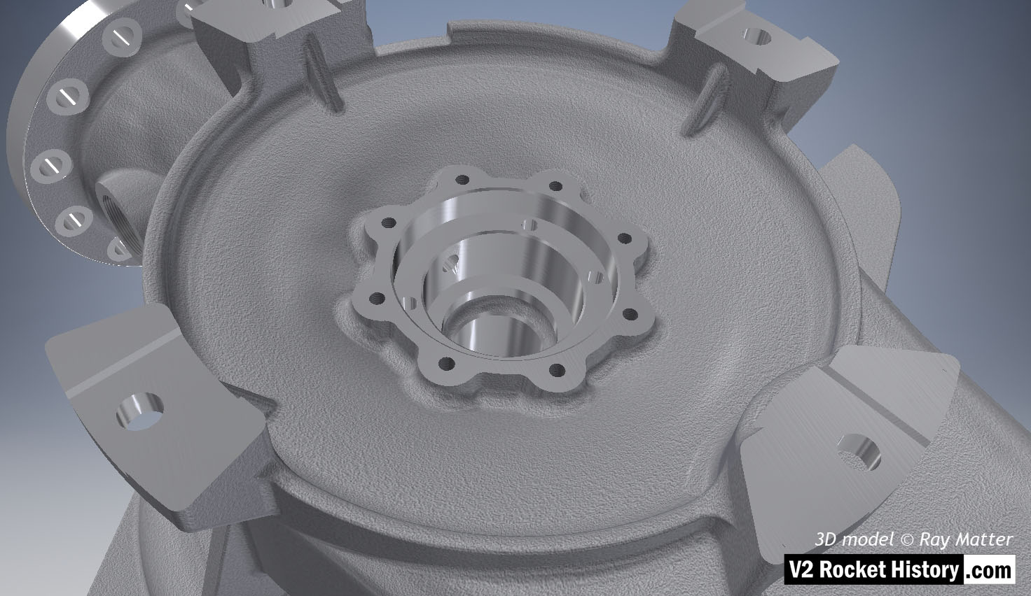
A (LOX) Pump sub-assembly, showing the face nearest the steam turbine. Single piece casting showing machined (milled) areas and detail of bearing and seal cavity. The four turbine case fitting brackets are displayed. 3D model Ray Matter
| Album | Turbopump 3D CAD |
| Category | Turbo-pump |
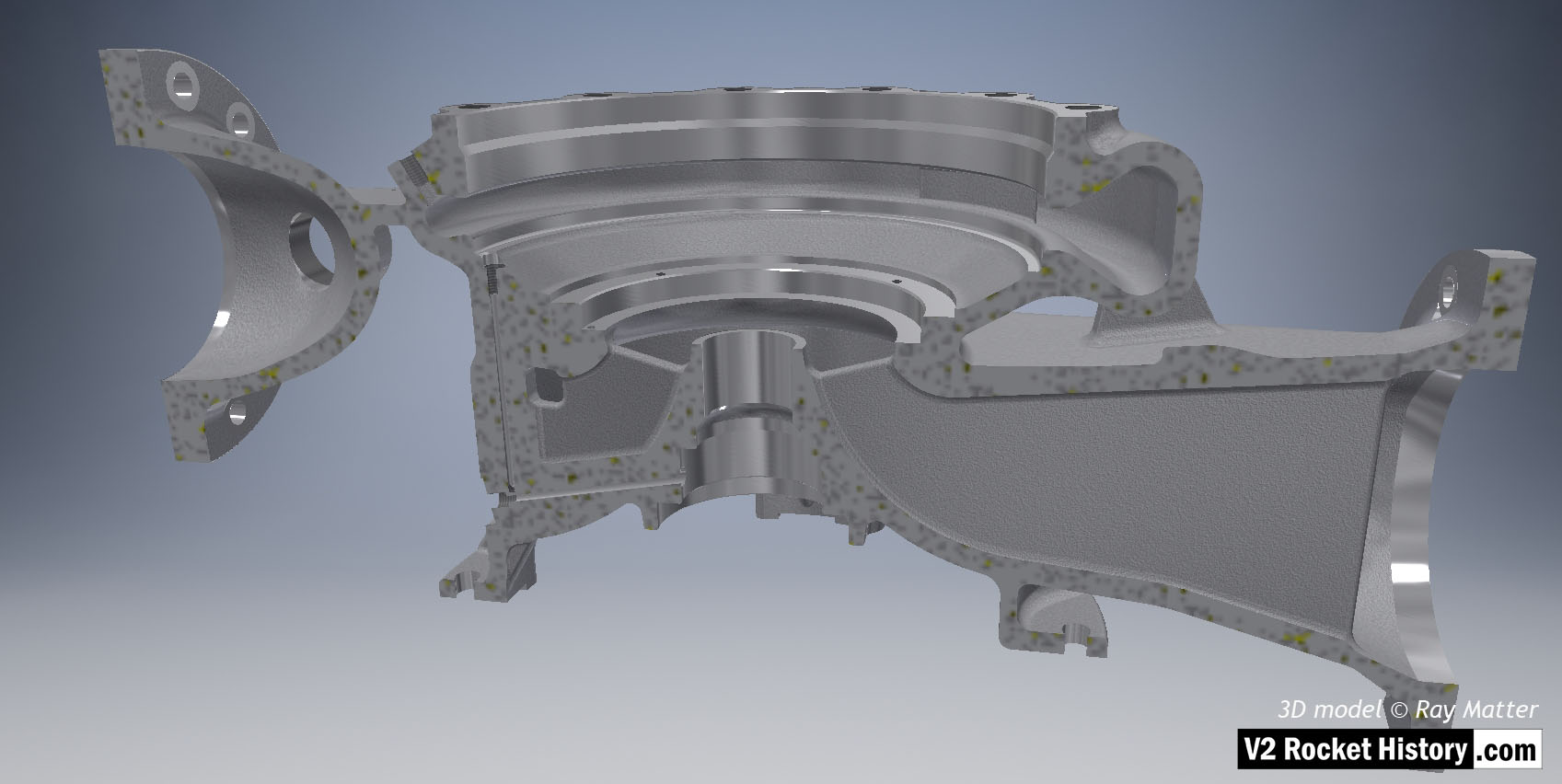
A (LOX) Pump housing sectioned to show baffle and volute space area expansion as flow passes from inlet (right) to outlet (left). Note cast and machined (milled) areas shown in this image – especially inlet aperture. 3D model Ray Matter
| Album | Turbopump 3D CAD |
| Category | Turbo-pump |
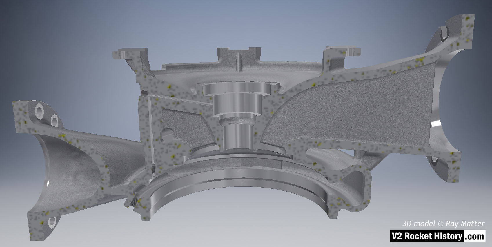
A (LOX) Pump housing sectioned to show baffle and volute space area expansion as flow passes from inlet (right) to outlet (left). Note the small LOX passageways on left from high-pressure volute space to bearing cavity. 3D model Ray Matter
| Album | Turbopump 3D CAD |
| Category | Turbo-pump |
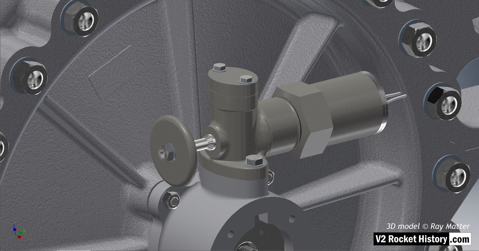
Detail of fuel pump face plate showing over-speed switch and mounting. The switch plunger (part with disc shaped hand knob on left) is shown in the out or armed position. The RPM of the tubo-pump (TP) was not governed but this safety mechanism shut the TP down permanently when the RPM reached 5000. Although rarely changed, thin shims could be used to reduce or increase this speed. 3D model Ray Matter
| Album | Turbopump 3D CAD |
| Category | Turbo-pump |
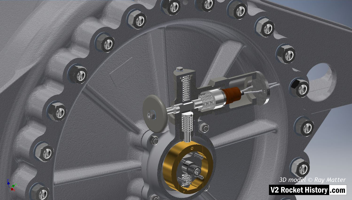
Detail of fuel pump face plate showing over-speed switch and mounting. The eccentric centrifugal rotor can be seen (brass coloured part). This unbalanced part rotates against a spring load that allows the thicker (proportionally heavier) section of the rotor to move outwards from the center as the rotational speed rises and push the release rod clear of a keyed section of the plunger shaft (part with disc shaped knob on left) thus operating a relay switch that shuts down the flow of steam to the turbine. 3D model Ray Matter
| Album | Turbopump 3D CAD |
| Category | Turbo-pump |
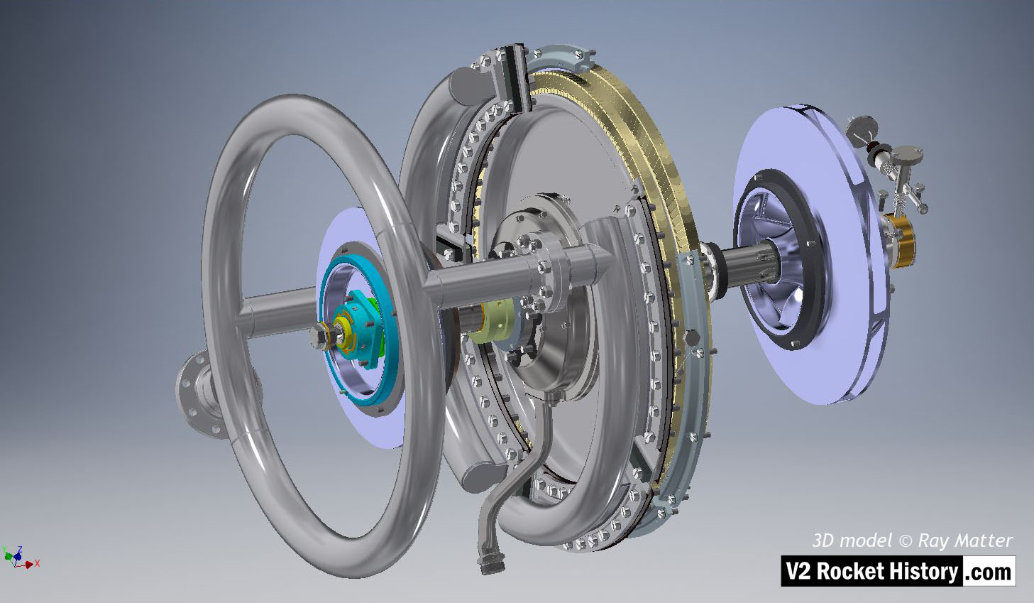
V2 turbo-pump turbine and pump impeller shaft assembly showing steam turbine rotor with nozzle assembly and steam inlet manifold distributor ring. The two rows of steam buckets can seen on rotor rim. Fuel pump impeller (purple) and over-speed switch are shown to the right. LOX pump impeller (purple) with journal bearing box and four sectional bronze bearings visible. An overboard dump pipe can be seen lower left of steam rotor. 3D model Ray Matter
| Album | Turbopump 3D CAD |
| Category | Turbo-pump |
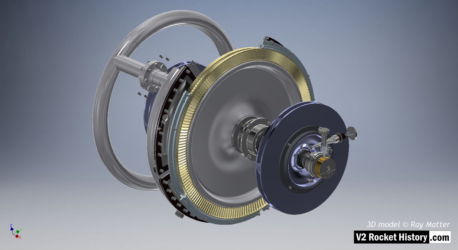
V2 turbo-pump turbine and pump impeller shaft assembly showing steam turbine rotor with nozzle assembly and steam inlet manifold distributor ring to left. The two rows of steam buckets can seen on rotor rim as well as three of the four sets of stationary steam return blades. Fuel pump impeller and over-speed switch are shown to the right. 3D model Ray Matter
| Album | Turbopump 3D CAD |
| Category | Turbo-pump |
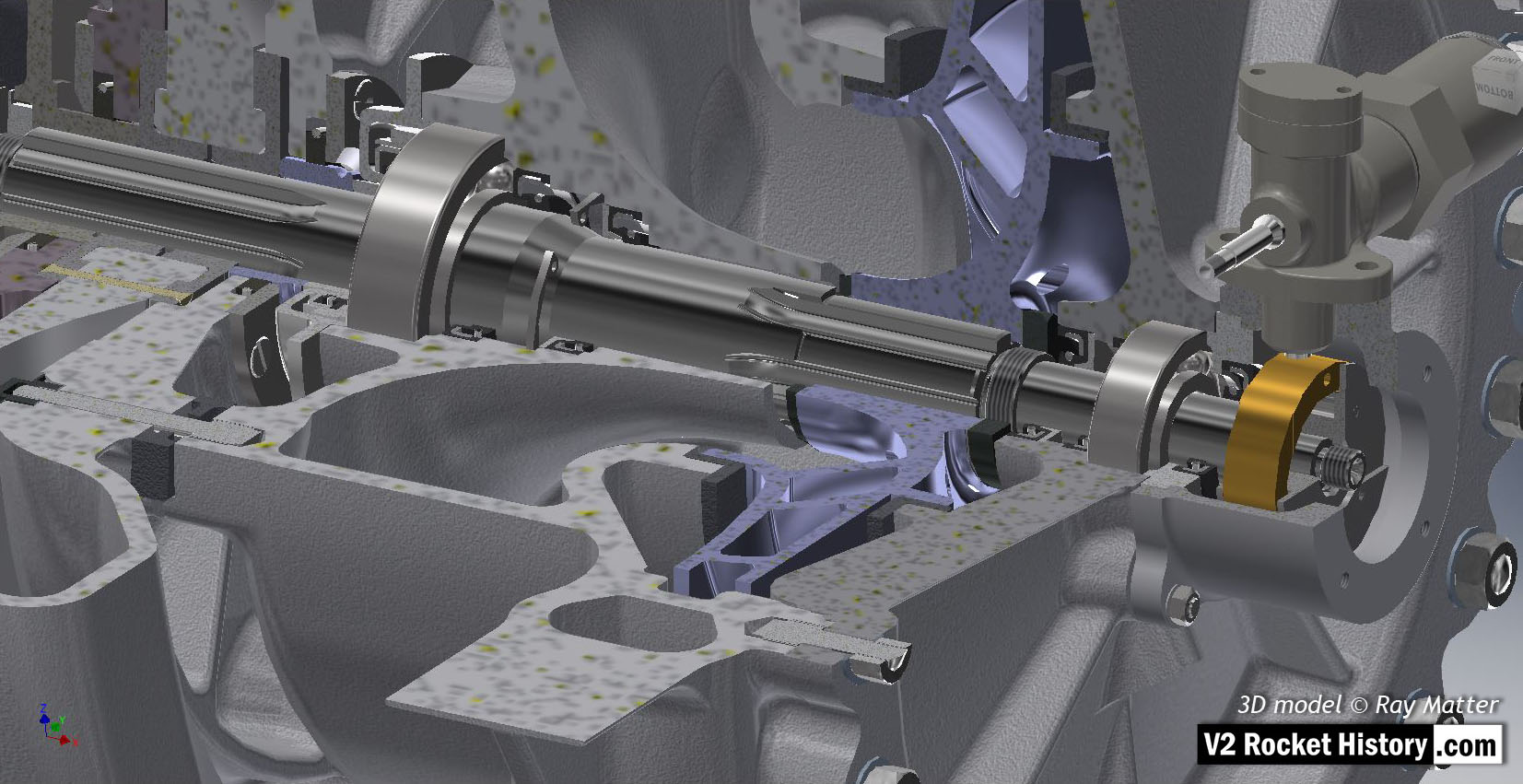
B (fuel) Pump: Close-up of sectioned turbine and pump impellers. Pump impeller (purple) and turbine rotor, top left, showing, seals, bearings and over-speed centrifugal rotor assembly. 3D model Ray Matte
| Album | Turbopump 3D CAD |
| Category | Turbo-pump |
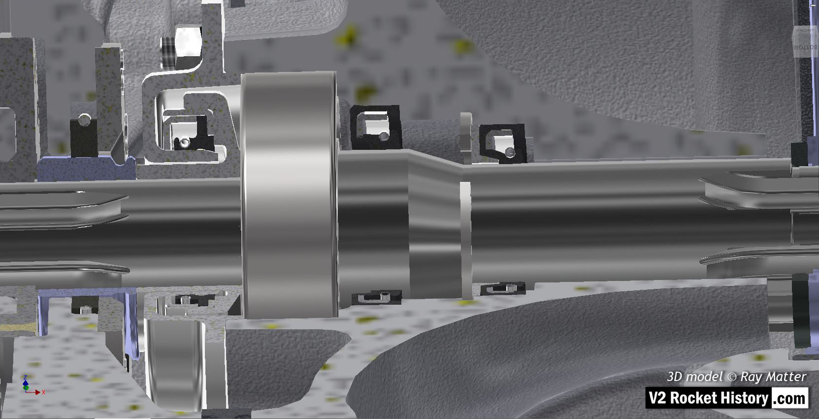
06 B Pump close-up showing shaft bearing and isolation seals at at pump to turbine mating point. 3D model Ray Matter
| Album | Turbopump 3D CAD |
| Category | Turbo-pump |
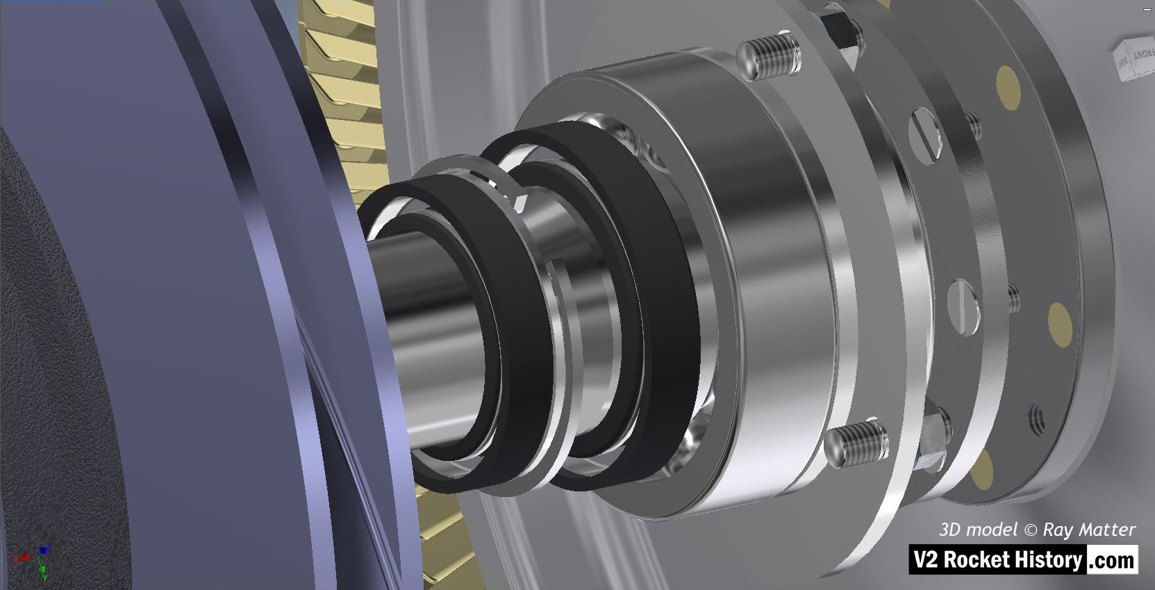
06 B Pump showing shaft area from fuel pump impeller, left (purple), to steam rotor. Shows seals, packer, circlip, and steam rotor hub. 3D model Ray Matter
| Album | Turbopump 3D CAD |
| Category | Turbo-pump |
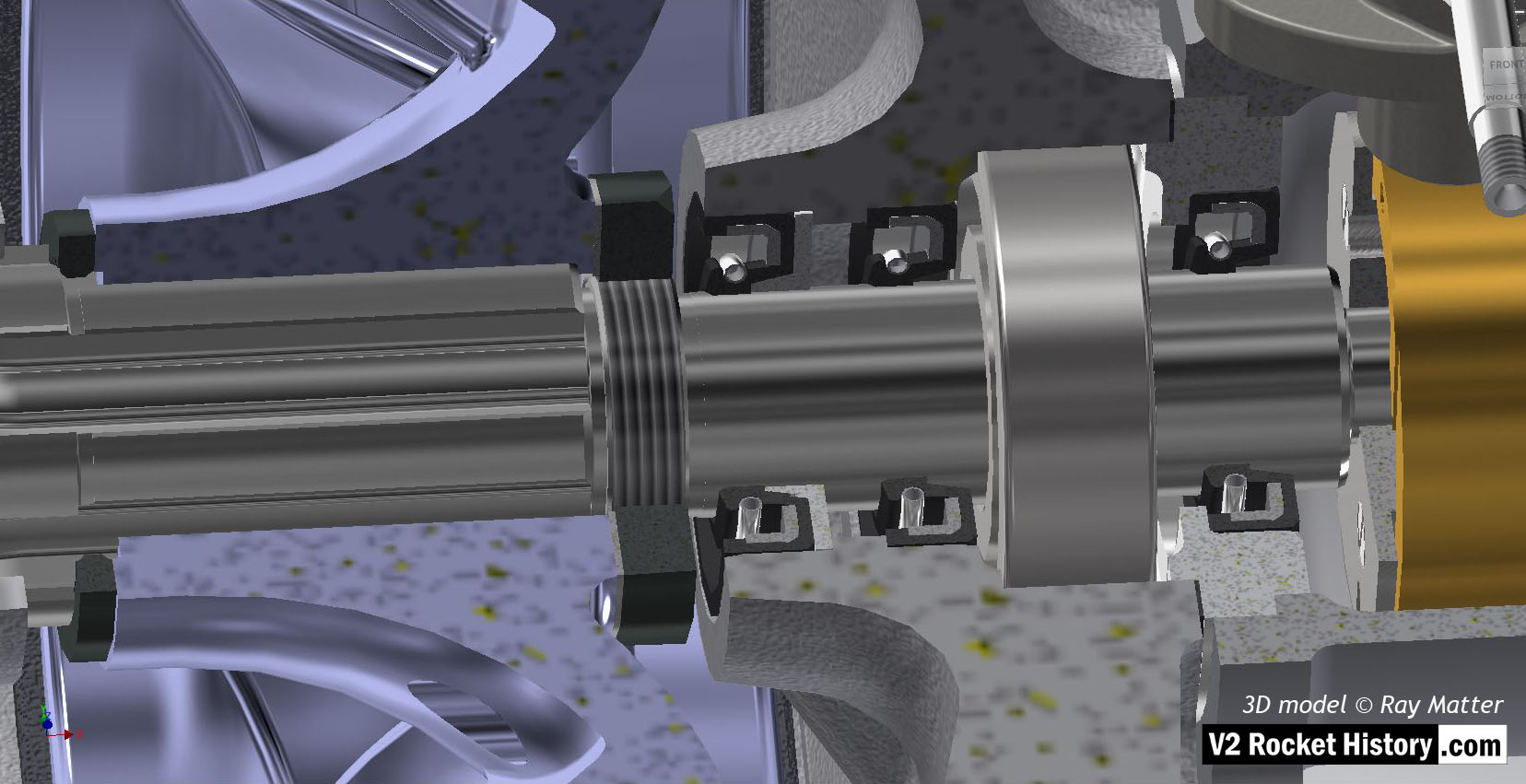
B (fuel) Pump: Close-up of sectioned pump impeller hub (purple) showing, left to right, seals, bearing and over-speed centrifugal rotor. 3D model Ray Matter
| Album | Turbopump 3D CAD |
| Category | Turbo-pump |
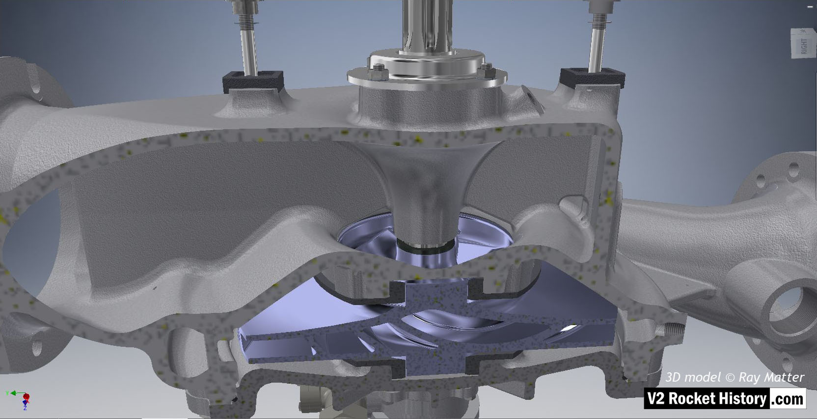
B (fuel) pump sub-assembly showing sectioned casing to reveal centrifugal pump impeller (in light purple for visibility). Outlet to right. Note inlet throat purge aperture of left. 3D model Ray Matter
| Album | Turbopump 3D CAD |
| Category | Turbo-pump |
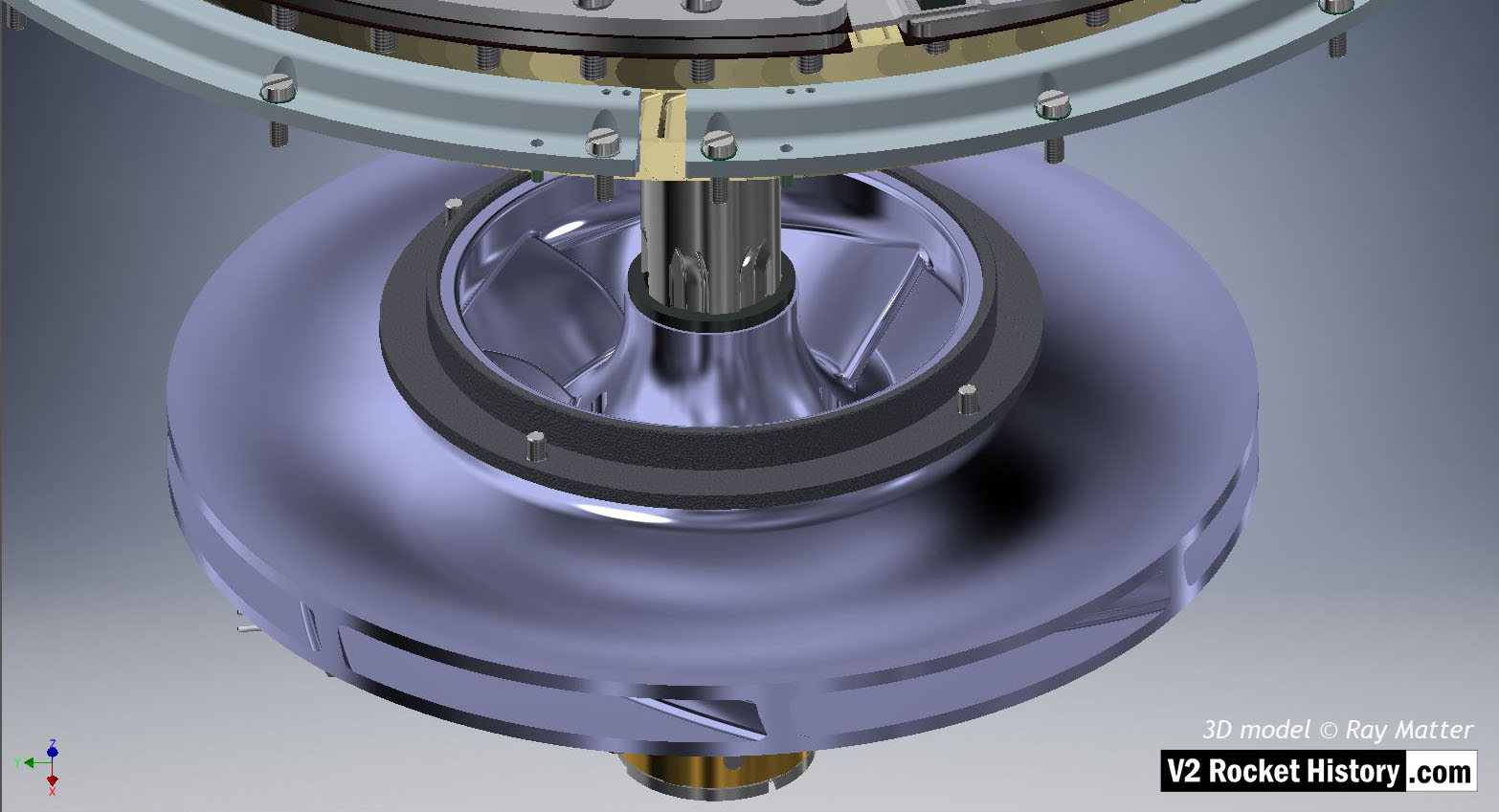
B pump casing removed to show fuel pump impeller and bearing ring. The steam rotor assembly can be seen at the top of the image and two sets of the stationary steam blades, or stators, are also visible.
| Album | Turbopump 3D CAD |
| Category | Turbo-pump |
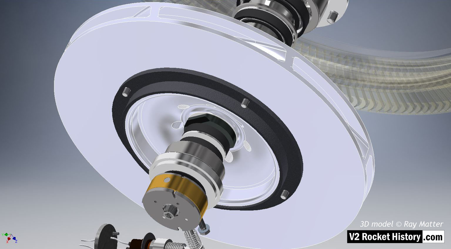
B (fuel) Pump exposed to show pump impeller, large bearing surface, and parts of over-speed device. 3D model Ray Matter
| Album | Turbopump 3D CAD |
| Category | Turbo-pump |
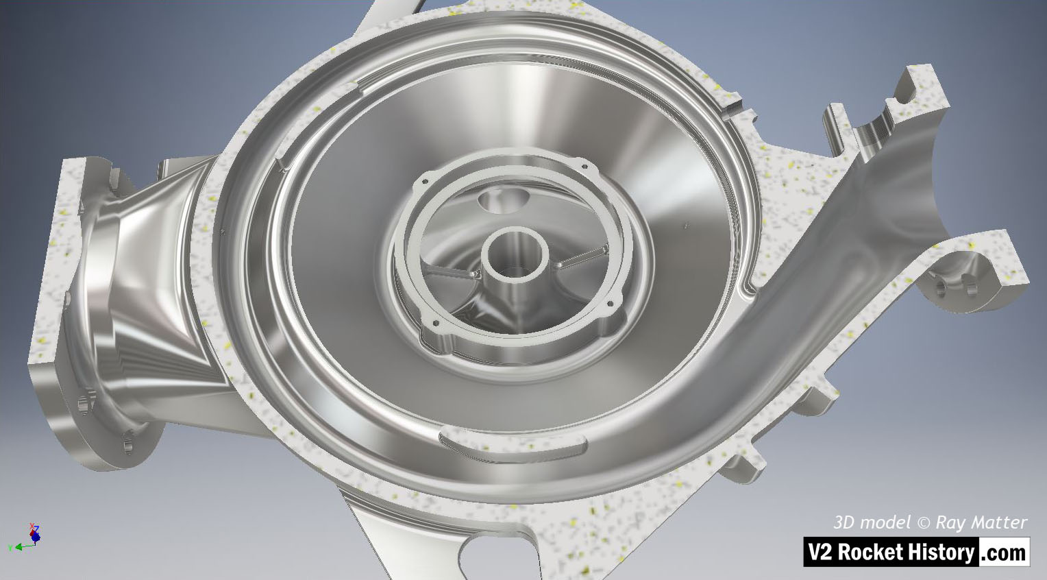
B pump housing from pump rotor side – notional surface polish to show shape and detail (such a surface was not used on the actual pump parts). The casing has been cut to show the internal rotor space detail. The outlet throat, right, and spiral volute space are displayed in this view as is the central fuel inlet. 3D model Ray Matter
| Album | Turbopump 3D CAD |
| Category | Turbo-pump |
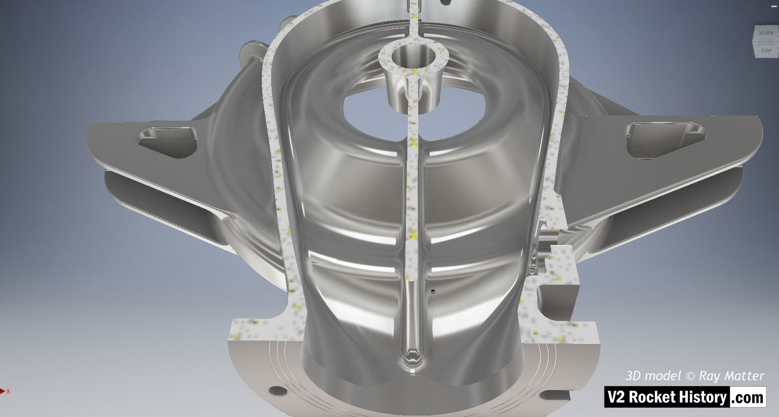
B pump housing with notional surface polish to show shape and detail (such a surface was not used on the actual pump casing). The casing nearest the turbine has been cutaway to reveal internal detail. The small self-purge orifice can be seen in this view, lower middle to the right of separator. 3D model Ray Matter
| Album | Turbopump 3D CAD |
| Category | Turbo-pump |
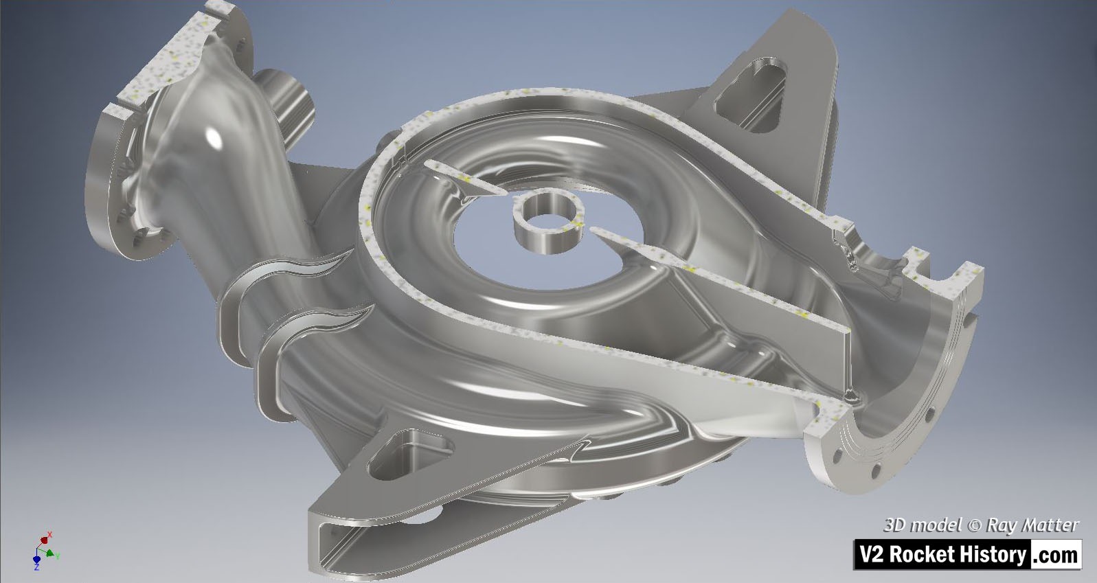
B pump housing with notional surface polish to show shape and detail (such a surface was not used on the actual pump casing). The casing nearest turbine has been cut to show internal detail. Inlet flange and split throat detail are clear in this view.
| Album | Turbopump 3D CAD |
| Category | Turbo-pump |

Valves
Images of the main valves involved in the propellant flow of the A4 / V2 liquid fuelled rocket engine
Categories: V2 Missile relics
Tags: #Combustion and injection #Thrust chamber #V2 Missile relics #V2 in combat
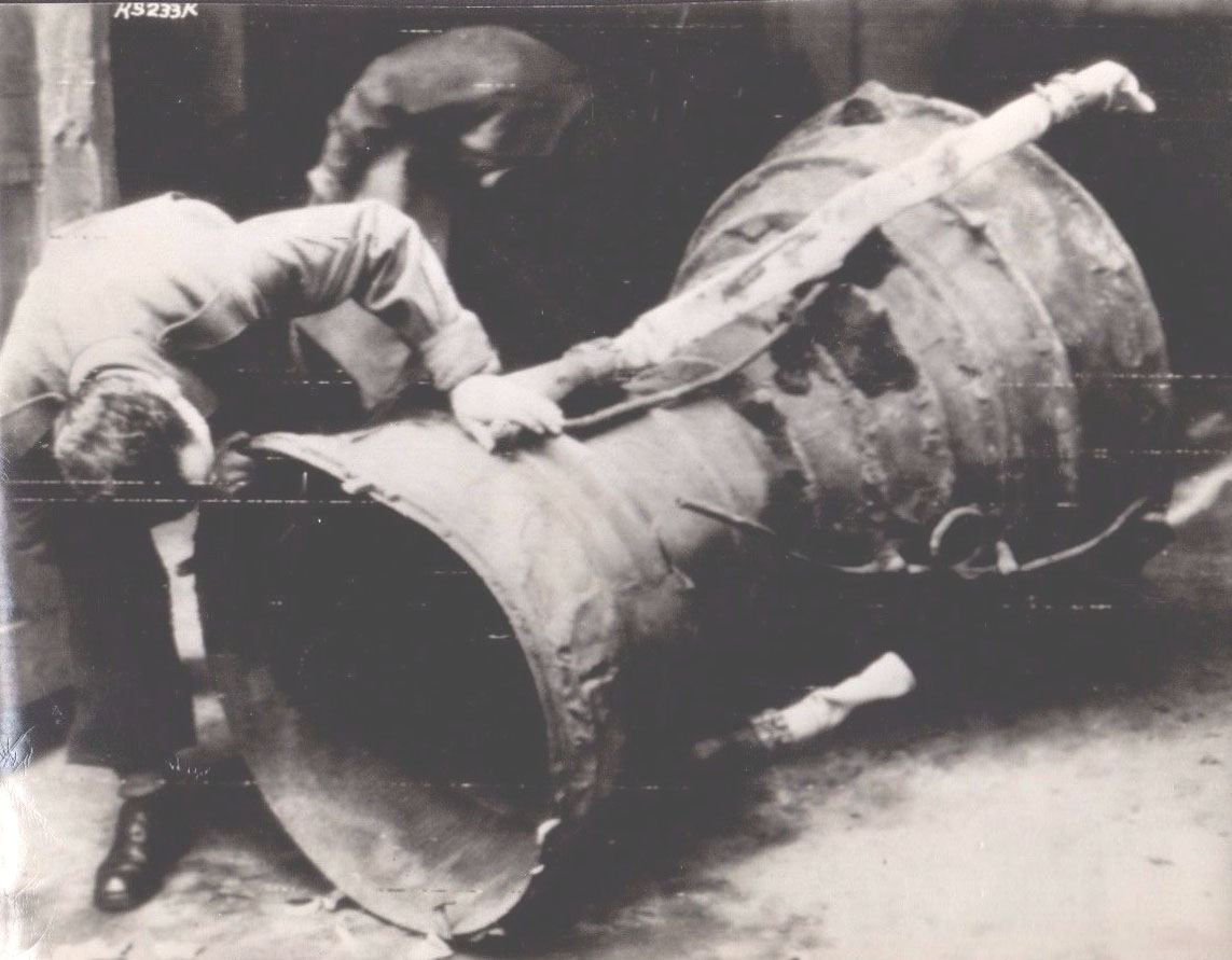
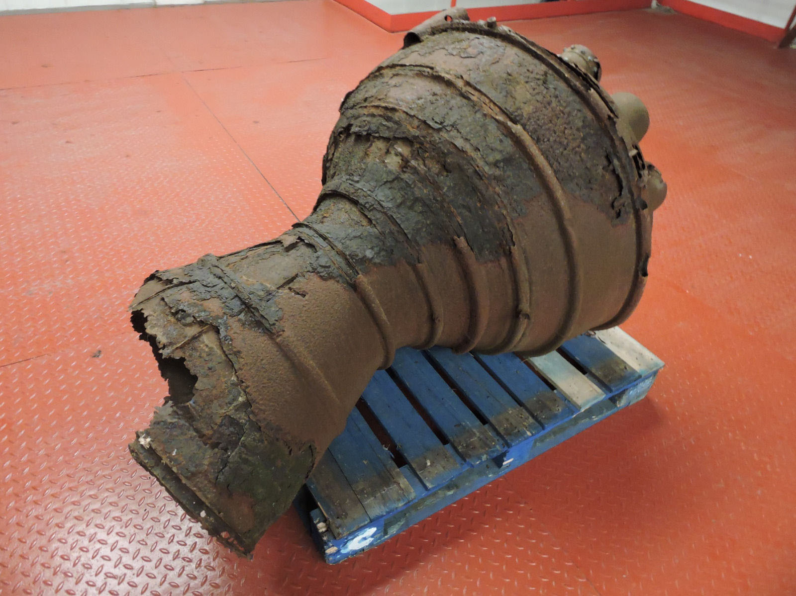
Examination of V2 missile thrust chamber. Sections of two of the large bore aluminium alcohol inlet manifold feed pipes and two thin steel veil colling supply pipes are still attached. The distinctive heat expansion relief loop can be seen on one of the pipes.

Anatomy of the V2: 18-pot injector head
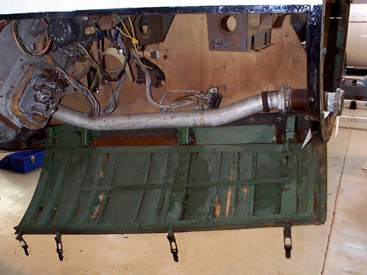
Control compartments 3 showing gyro mounting platform with two gyros and DC motor driven 3 phase AC voltage generator. The alcohol tank pressurisation pipe is also shown running through the equipment bay (large silver coloured pipe). Image copyright Imperial War Museum
| Album | Equipment bays |
| Category | Guidence |
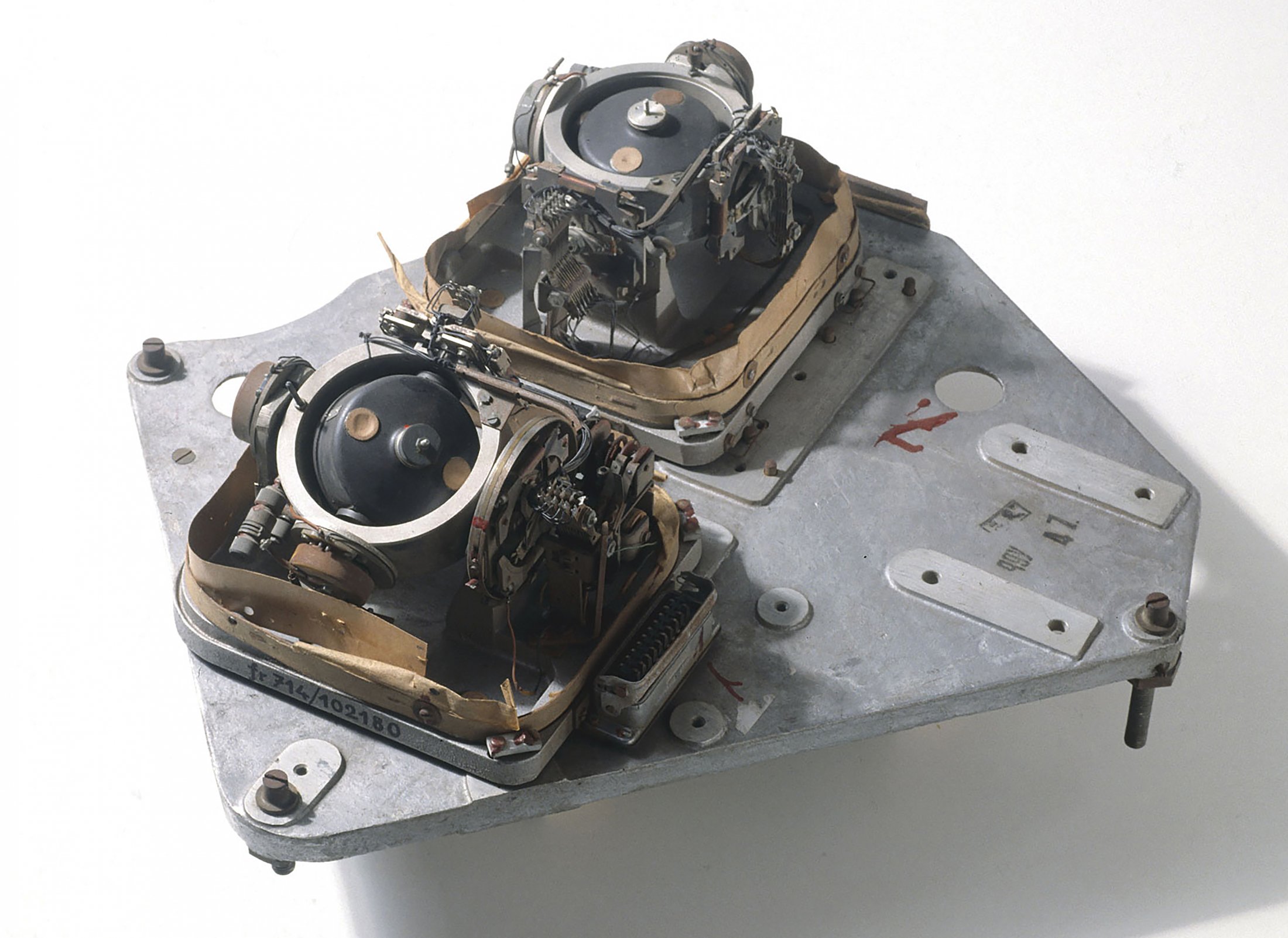
LEV-3 V2 missile gyroscope system with mounting plate. The third component of this system, the Muller gyroscopic accelerometer, is missing – the 2x mounting points can be seen on the right-hand side of the mounting plate.
| Album | Missile guidance equipment |
| Categories | Missile guidence, Sub-assemblies |
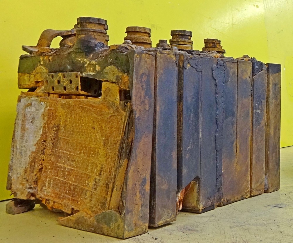
Photo shows rare surviving complete set of 8 lead acid battery cells from one of the V2 rocket’s 32 volt (100 amp) lead acid batteries. Two sets of batteries like this were used to provide the direct current (DC) voltage used aboard the V2 missile to power the DC to 3-phase alternating current (AC) generators, that in turn, powered the gyroscopes, electro-hydraulic servos, trim motors and other vital guidance and control devices. Photo copyright: The Horst Beck Collection
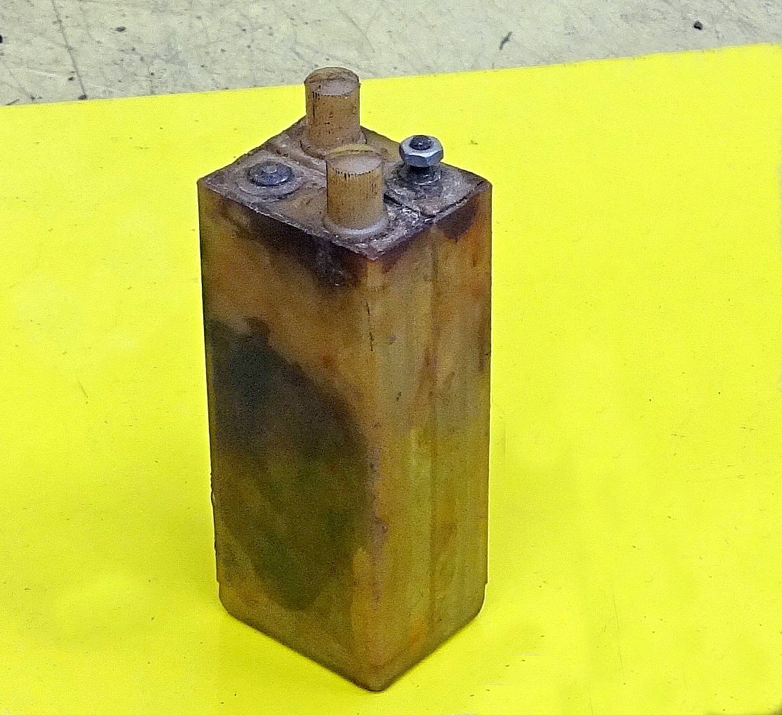
Photo shows rare surviving 1.2 volt cell from the V2 missile’s 50 volt command or signalling battery used in its gyro guidance system (note, the terminal connection on the left is missing from this exhibit, it would be identical to the one on the right). This wet nickel-cadmium battery cell was combined in pairs to a total set of 21 providing a 50.4 voltage at 300mA. The cells were contained in a wooden box that was held on a rack in equipment bay III. Its function was to provide the direct current (DC) signalling voltage that communicated the moment to moment resistance of the gyroscope’s potentiometers to the analog guidance computer (Mischgerät = Mixer-device or control amplifier) aboard the V2 missile. It was critical that the signalling voltage was maintained between 48 and 50.4 volts. Photo copyright: The Horst Beck Collection
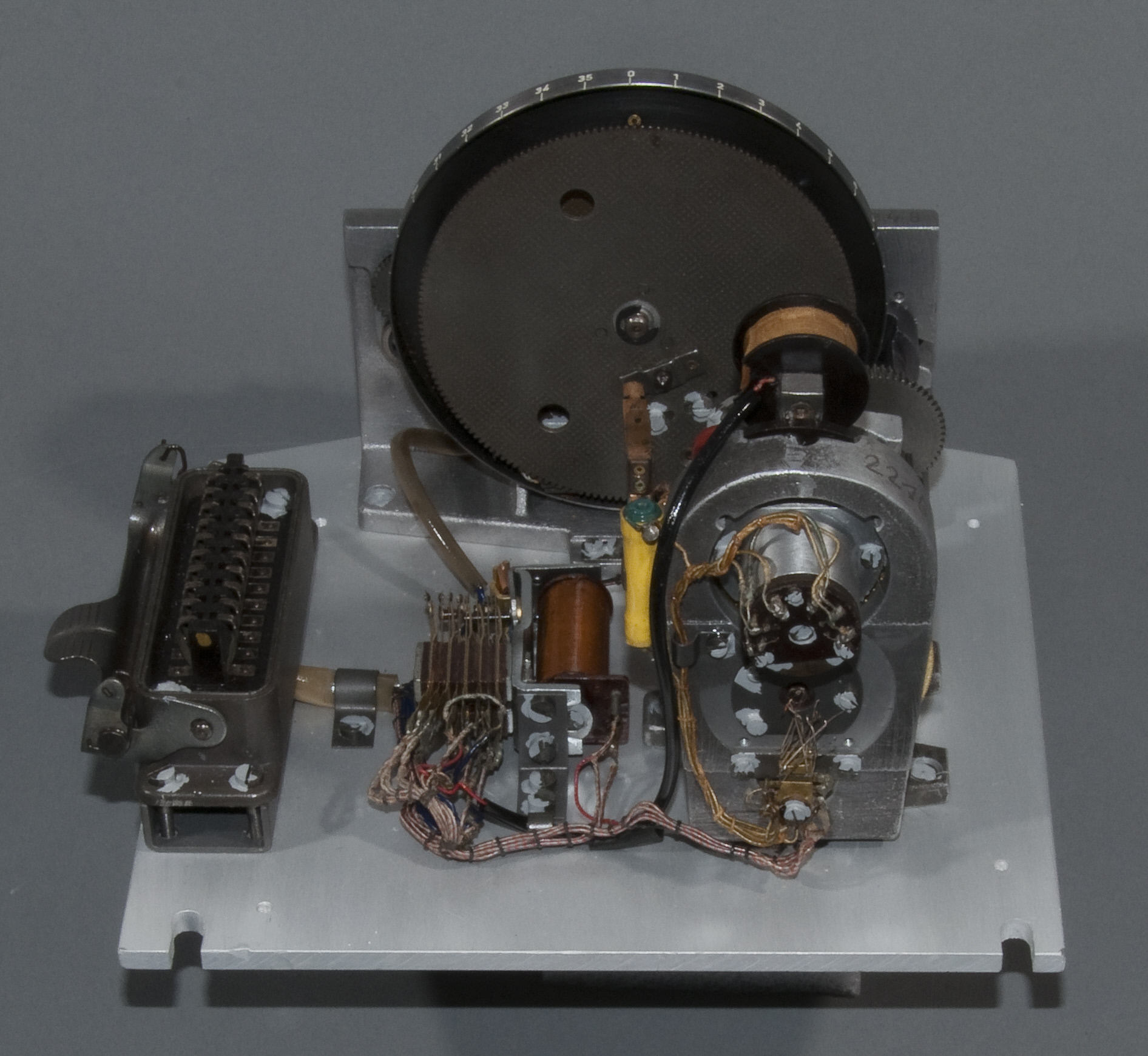
The Muller mechanical or Pendulous Integrating Gyroscopic Accelerometer – today normally referred to as a PIGA. Designed by Fritz K Muller.
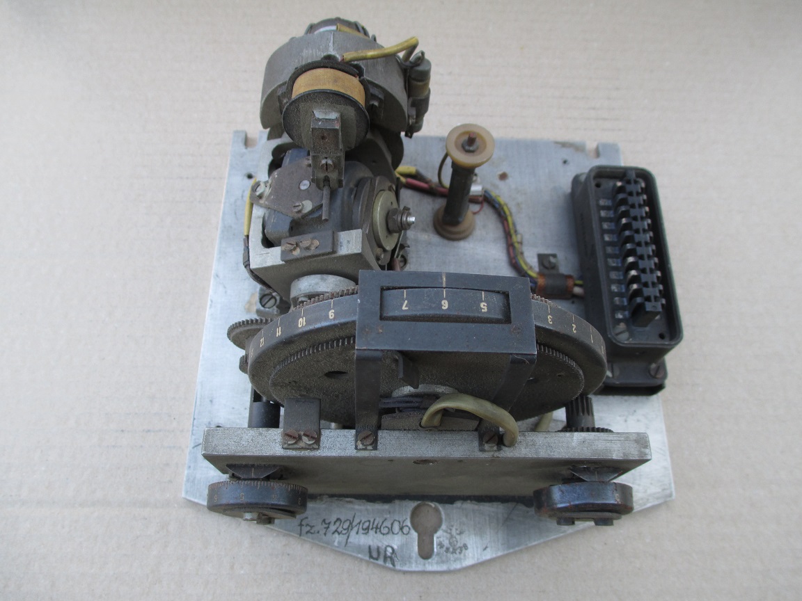
The J device no1 (J Gerate Eins). The full name of this device is: the Muller Pendulous (or mechanical) Integrating Gyroscopic Accelerometer – today normally referred to as a PIGA. The device, designed by Fritz K Muller, operates as a switch to initiate rocket engine shutdown and is able to smoothly record and accumulate every moment of acceleration, without any kind of recording resolution or discrete time interval limit, of the rocket’s entire motor burn phase, and at the same time process this accumulated acceleration with respect to time as a gradually increasing velocity. In the case of the V2 missile, when the correct predetermined velocity is reached, the velicity sufficient to achieve the desired range of the missile, the device trips the relays that close valves that shutdown the supply of steam to the turbo-pump, and thus shutdown the rocket motor itself.

Testing fuel injectors




Industrial magazine advert for Gustav Schlick printed in 1918 and showing graphic of steam boiler jets. The company, formed in 1902, had a wide expertise in all aspects of industrial spray technology and were able to steer the direction of fuel injector development along fruitful lines after they became consulting contractors to Dr Walter Thiel’s combustion research group in 1937.

