For more detailed images see the image gallery at the bottom of this post
The eighteen pot injector head.
This is the first image blog from Alexsander Savochkin in what we hope will become an expanding resource for those wishing to find out more about the design and construction of the A4/V2 missile. The precise 3D CAD model imagery is based exclusively on original drawings produced in Germany from 1940 to 1945. When enough material has been uploaded we will create a fixed menu item called ‘Anatomy of the V2‘ where we hope to be able to offer coverage of the entire missile in detailed 3D models like the ones shown here – Robert J. Dalby, editor in chief, V2 Rocket History.com
View of injector head showing liquid propellant (LOX and fuel) diffuser cups and head fuel valve seating ring at centre, (see other images for insert and position nomenclature). Visible immediately below the valve seat are the large connecting holes that allow fuel to flow from the inlet manifold and cooling jacket to the injector space (some brass injector inserts can be seen through the holes) after the head fuel valve is released to be opened by the turbo-pump supply pressure. The four veil cooling inlet connectors are well shown as are two of the outlet connection holes immediately above them. 3D model by Alexander SavochkinA close-up view of the head fuel valve mounting flange (showing 12 fastener holes). Visible immediately below the top flange are the large connecting holes that allow fuel to flow from the inlet manifold and cooling jacket to the injector space (some brass injector inserts can be seen through the holes) after the head fuel valve is released to be opened by the turbo-pump supply pressure.Inverted view of injector head showing liquid propellant (LOX and fuel) diffuser cups, (see other images for insert and position nomenclature). Of note in this image are the pointing angles of the cups, positioned on a parabolic section to focus the propellant nebular stream into the central axis of the combustion space. Also of note are the large areas between each cup NOT employed in the injection process leading to structured propellant mixing as opposed to even homogeneous mixing. The four veil cooling inlet connectors are well shown. 3D model by Alexander SavochkinUnderside view of injector head showing liquid propellant (LOX and fuel) diffuser cups, (see other images for insert and position nomenclature). Of note in this image are the pointing angles of the cups, positioned on a parabolic section to focus the propellant nebular stream into the central axis of the combustion space. Also of note are the large areas between each cup NOT employed in the injection process – initiating \’clumpy\’ and uneven propellant mixing initially below the injector face but also carried forward into the combustion space. The LOX spray head is shown in the centre of each cup. 3D model by Alexander SavochkinHere the 18-pot head model has been cut away to show the fuel cooling and fuel delivery spaces. the cooling jacket layer can be seen in the lowermost area of the head – below the centrally positioned fuel valve seat, between each cup at the lowest point, and running down toward the first set of veil cooling pores and the topmost coolant distributor ring. Note that the veil cooling system does not communicate with the regenerative cooling jacket and has its own feed pipes drawing fuel from the head injector space and not the cooling space. Visible immediately above the valve seat are the large connecting holes that allow fuel to flow from the inlet manifold and cooling jacket to the injector space after the head fuel valve is released to be opened by the turbo-pump supply pressure. 3D model by Alexander SavochkinClose-up detail showing independent pathway for fuel passing into injector head and fuel passed down from the head to be used for veil cooling system. Fig. A shows vertical passages for overall fuel feed to the head and Fig.B shows horizontal pathway for veil coolant fed from the head via the veil coolant distributor ring or manifold. 3D model by Alexander SavochkinLiquid propellant (LOX and fuel) diffuser cup, showing three rings or echelons (A, D,& E) of brass injector inserts as well as two rows of drilled fuel feed holes. The LOX spray head is shown in the centre. Note the simple ‘shower head or watering can’ design of the LOX diffuser. A sealing washer can be seen fitted between the LOX diffuser and the steel cup. 3D model by Alexander SavochkinView of the top of the injector head, with outer cups and pressed steel capping piece removed, showing, propellant diffuser inner cores with injector inserts and LOX supply pipe connection thread. The LOX spray head can be seen inside the LOX pipe connector. The swirl caps of fuel injector inserts in positions A, D,& E can be seen clearly on the outside of the cores and the two rows of drilled fuel feed holes are also well shown. 3D model by Alexander SavochkinGeneral view of the propellant diffuser cup inner core. The swirl caps of fuel injector inserts in positions A, D,& E can be seen clearly on the outside of the core as well as the central holes in the 3304D (red) inserts. The two rows of drilled fuel feed holes are also well shown. 3D model by Alexander Savochkin
Click the above video to see an animation of the diffuser cup inner core (the animation may take a few seconds to show at maximum resolution).
This image shows a burner cup from outer Ring I of the injector head and the cutaway shows injector insert echelon A, D, & E as well as two rows of drilled feed holes. Four fuel injector insert types can be seen: Top, A = 2131E, lower D, = 3303D (white), lowest E, = 3304D (red), and E, = 3305D (blue). 3D model by Alexander SavochkinCutaway showing echelon A with 2-part 2131E fuel injector inserts at the top of a propellant diffuser cup. Note the close proximity of the injector inserts to the simple ‘watering can’ type LOX spray head. One row of drilled fuel feed holes can be seen below the inserts. 3D model by Alexander SavochkinThis images shows a cutaway of a burner cup from outer Ring I of the injector head and shows injector insert echelon D, & E as well as one row of drilled feed holes. Three fuel injector insert types can be seen: Top D, = 3303D (white), lower E, = 3304D (red), and E, = 3305D (blue). 3D model by Alexander SavochkinOne of the 18 liquid propellants (LOX and fuel) diffuser cups, showing three rows or echelons (A, D,& E) of brass fuel injector inserts as well as two rows of drilled fuel feed holes. The LOX spray head is shown in the centre. 3D model by Alexander SavochkinExploded view showing some of the 1100 parts required for the complicated 18-pot injector head of the V2 25-ton thrust rocket engine. 3D model by Alexander Savochkin
The image gallery below has all the above pictures in higher resolution, some with additional text, as well as additional pictures not included in this post.
Steam manifold case: Lid Removed
Steam manifold case: Lid Removed
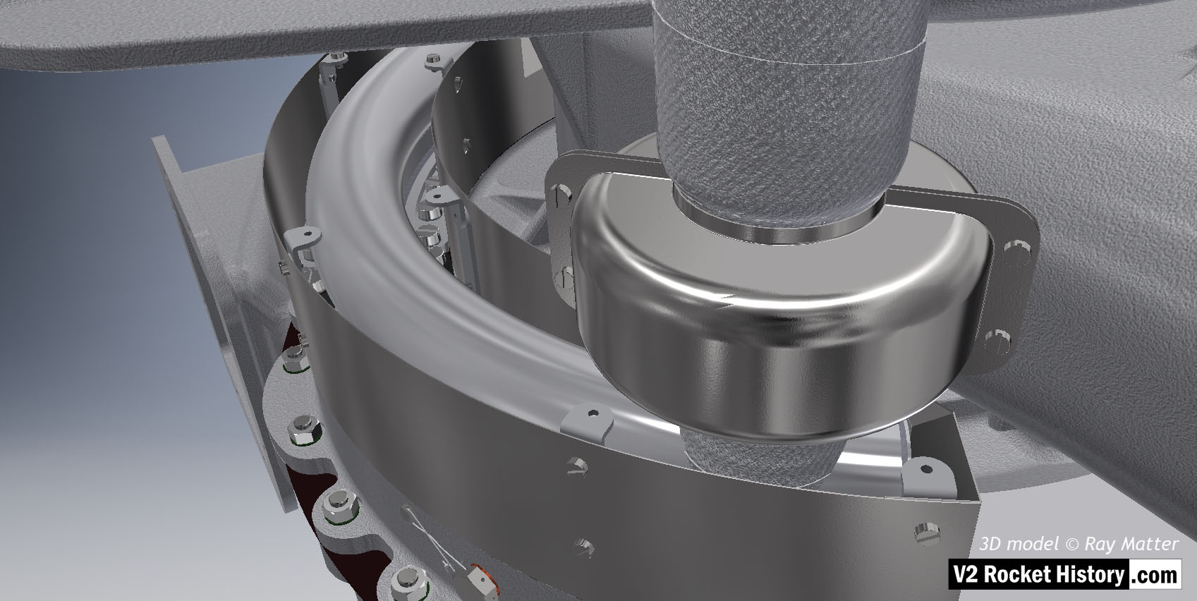
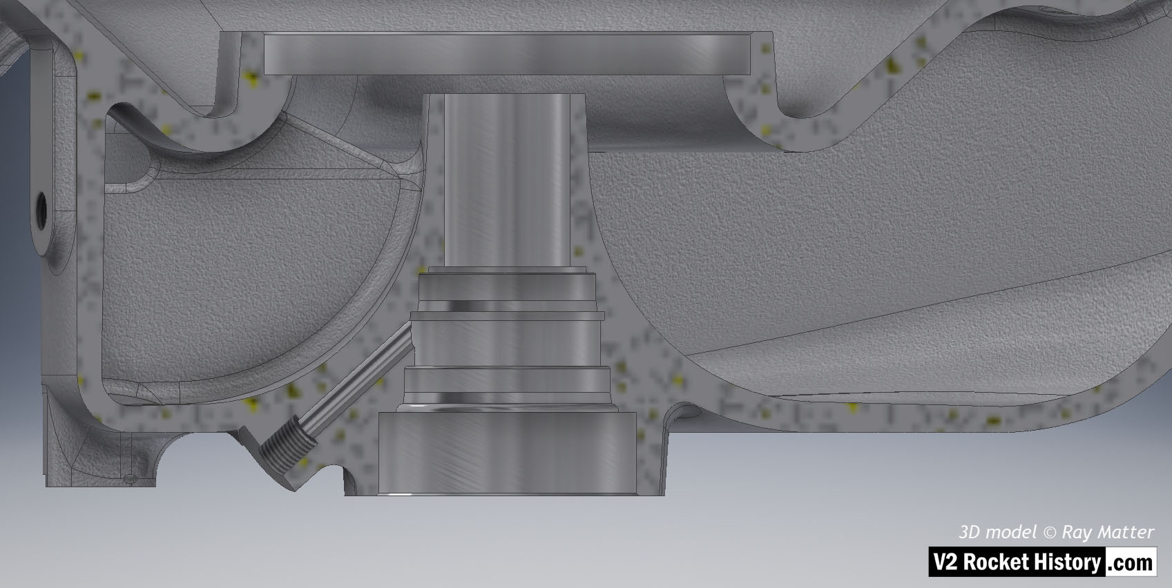
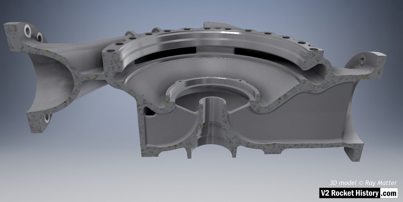
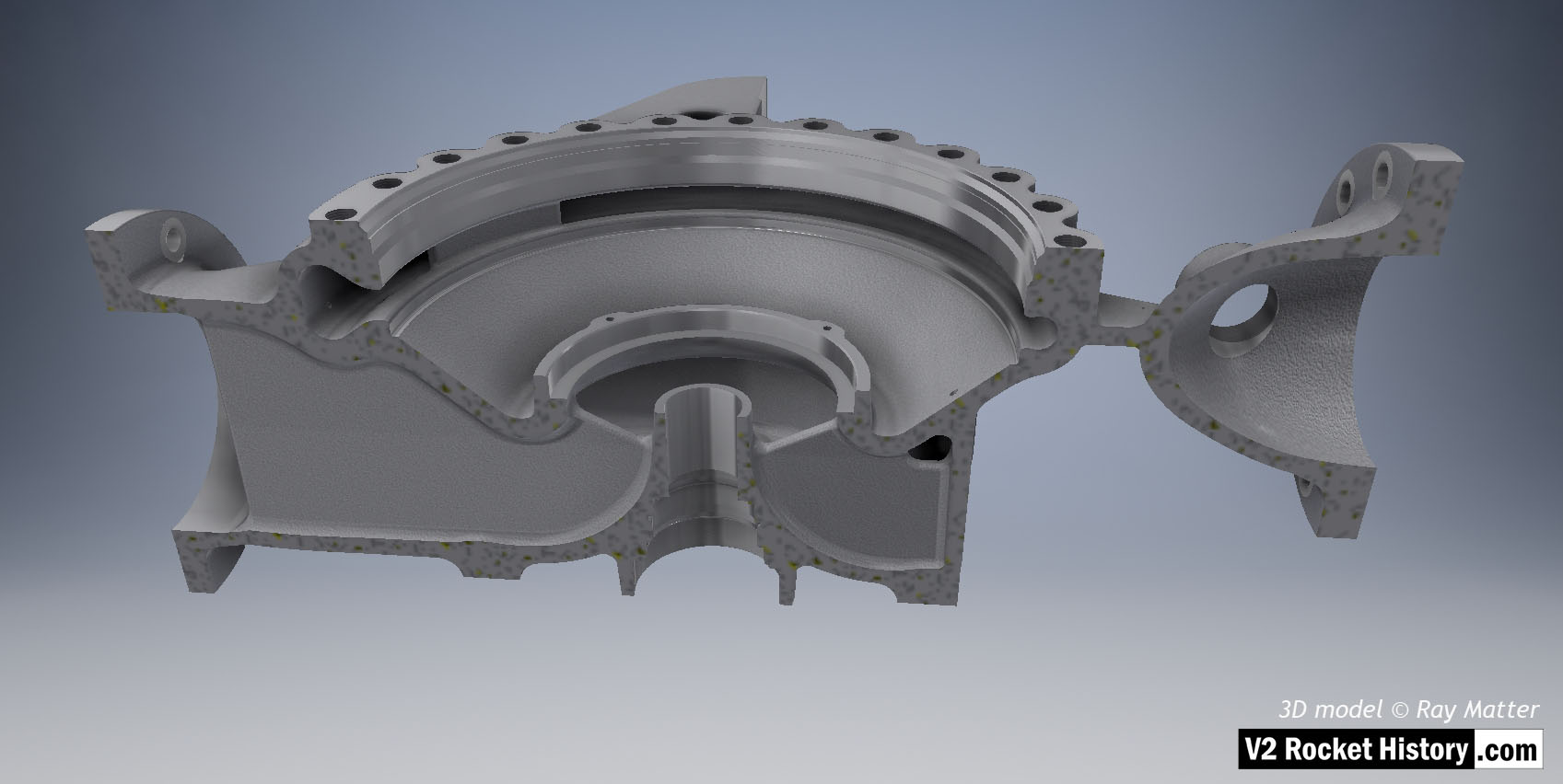
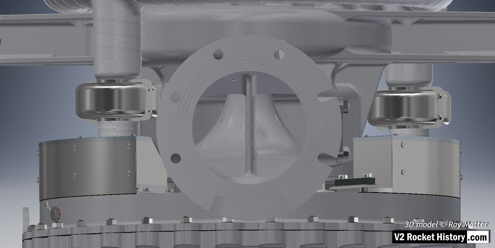
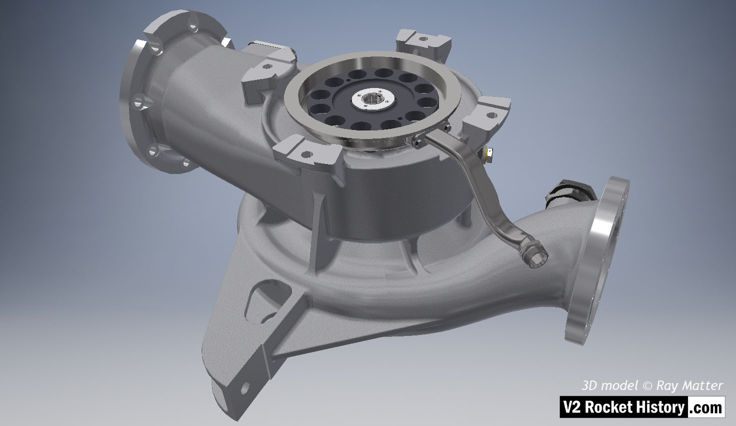
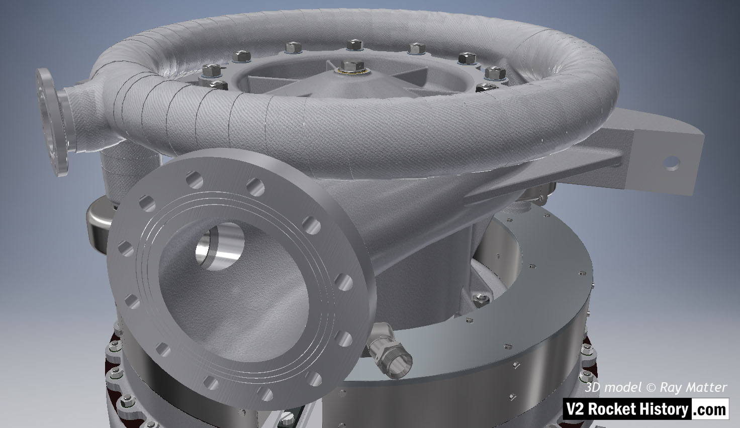
Close-up of turbine showing steel case with lid removed to show steam inlet ring manifold. The thin steel case that fits around the steam manifold mating flanges is clearly shown as is the wire restraint fastener locking system (see close-up in gallery). 3D model by Ray Matter
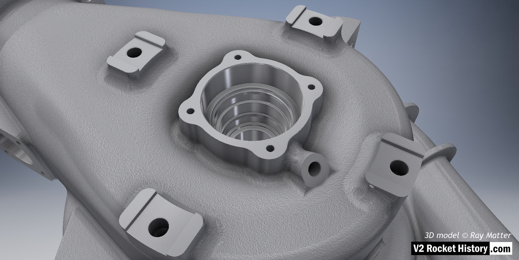
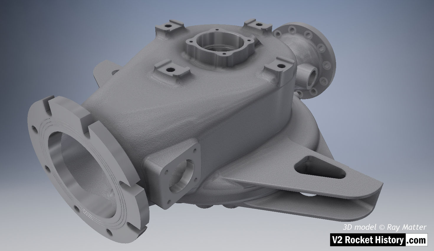
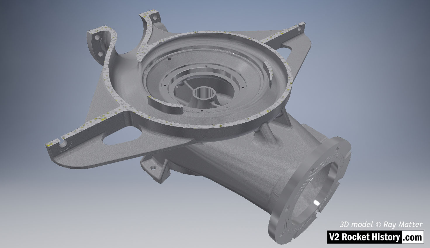
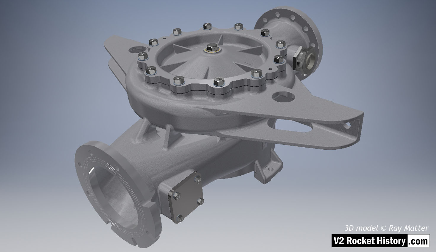
B (fuel) Pump sub-assembly shown without fittings. Single piece casting showing detail of bearing and seal cavity as well as threaded fuel bleed connection. 3D model Ray Matter
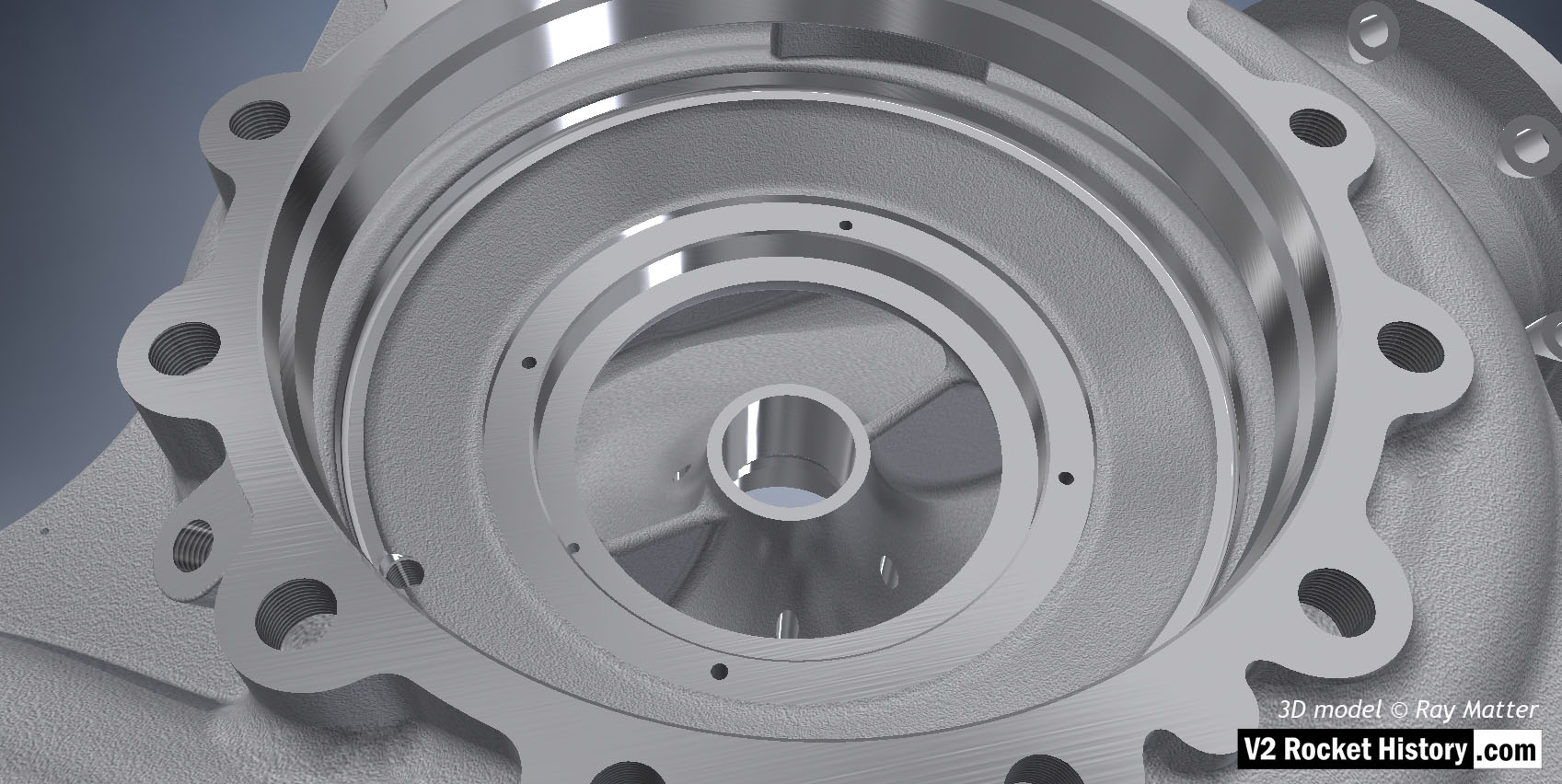
Close-up of 'B' fuel pump housing displaying cast and machined surfaces. Fuel inlet aperture shown with small purge orifice shown at 2 o'clock. 3D model by Ray Matter
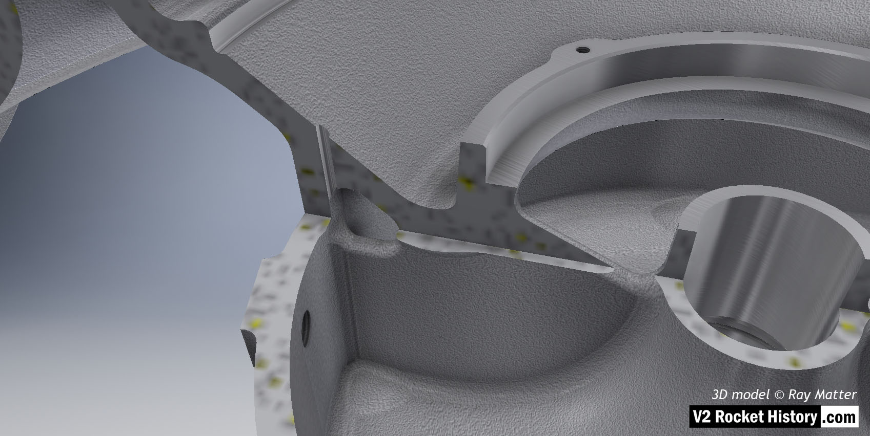
B Pump Housing, sectioned to show close-up of fuel bleed aperture and baffle vent for fuel pressure equalization between cavities inside the B pump casing. 3D model by Ray Matter
B Pump housing sectioned to show baffle with vent and volute space area expansion as flow passes from inlet (left) to outlet (right). 3D model Ray Matter
B (fuel) Pump sub-assembly, single piece casting showing machined (milled) areas without fittings. View shows inlet flange fastener slots and the throat aperture - facing right, initially blanked off by square plate, but towards the end of 1944 used for fuel return from the main fuel valve situated in the center of the thrust chamber injection head. 3D model Ray Matter
A (LOX) Pump close-up showing inlet flange, with fastener slots and holes, as well as the throat baffle. To the right and left of the flange, the steam inlets are shown - with steel cases covering the steam manifold connection flanges. Of special note in this view is the self-purge orifice seen at the top right-hand side of the inlet throat baffle. This hole allowed gas to escape from the top of the LOX volute space back to the low-pressure inlet throat and proved problematic in manufacturing and was revised in late 1944. 3D model Ray Matter
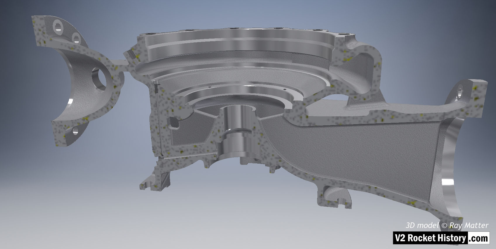
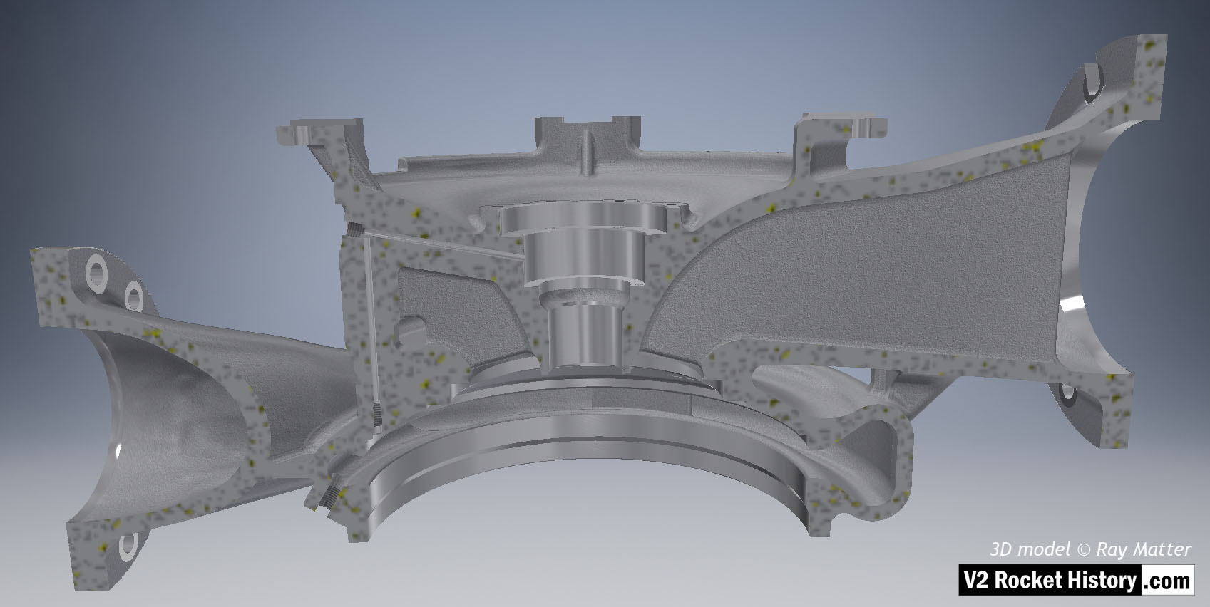
A (LOX) Pump housing sectioned to show baffle and volute space area expansion as flow passes from inlet (right) to outlet (left). Note cast and machined (milled) areas shown in this image - especially inlet aperture. 3D model Ray Matter
A (LOX) Pump housing sectioned to show baffle and volute space area expansion as flow passes from inlet (right) to outlet (left). Note the small LOX passageways on left from high-pressure volute space to bearing cavity. 3D model Ray Matter
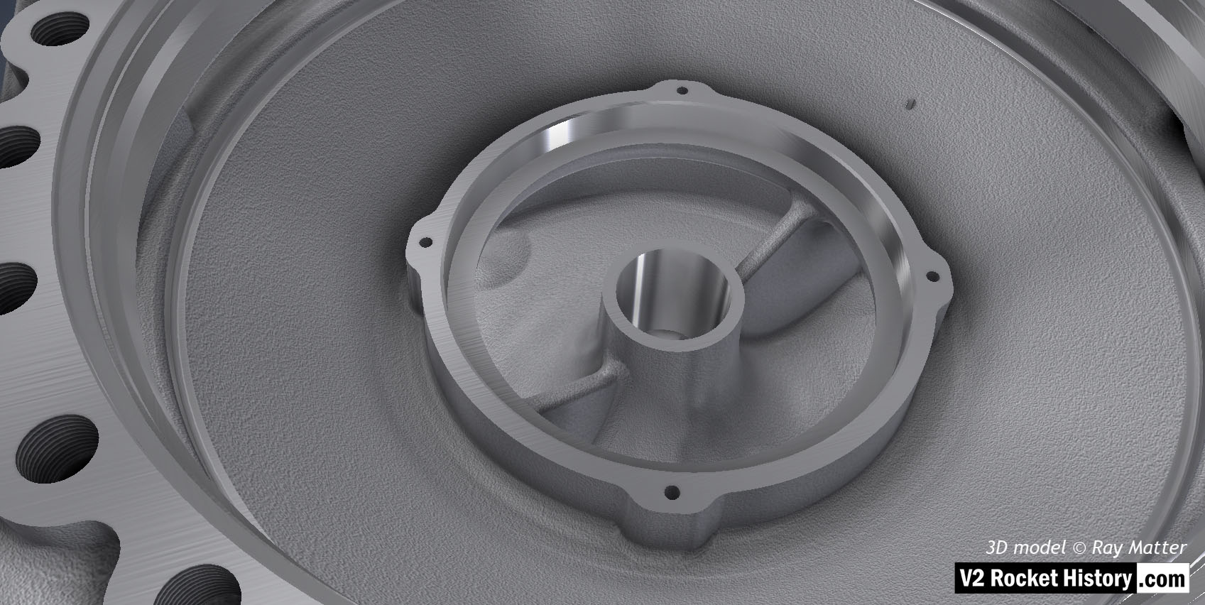
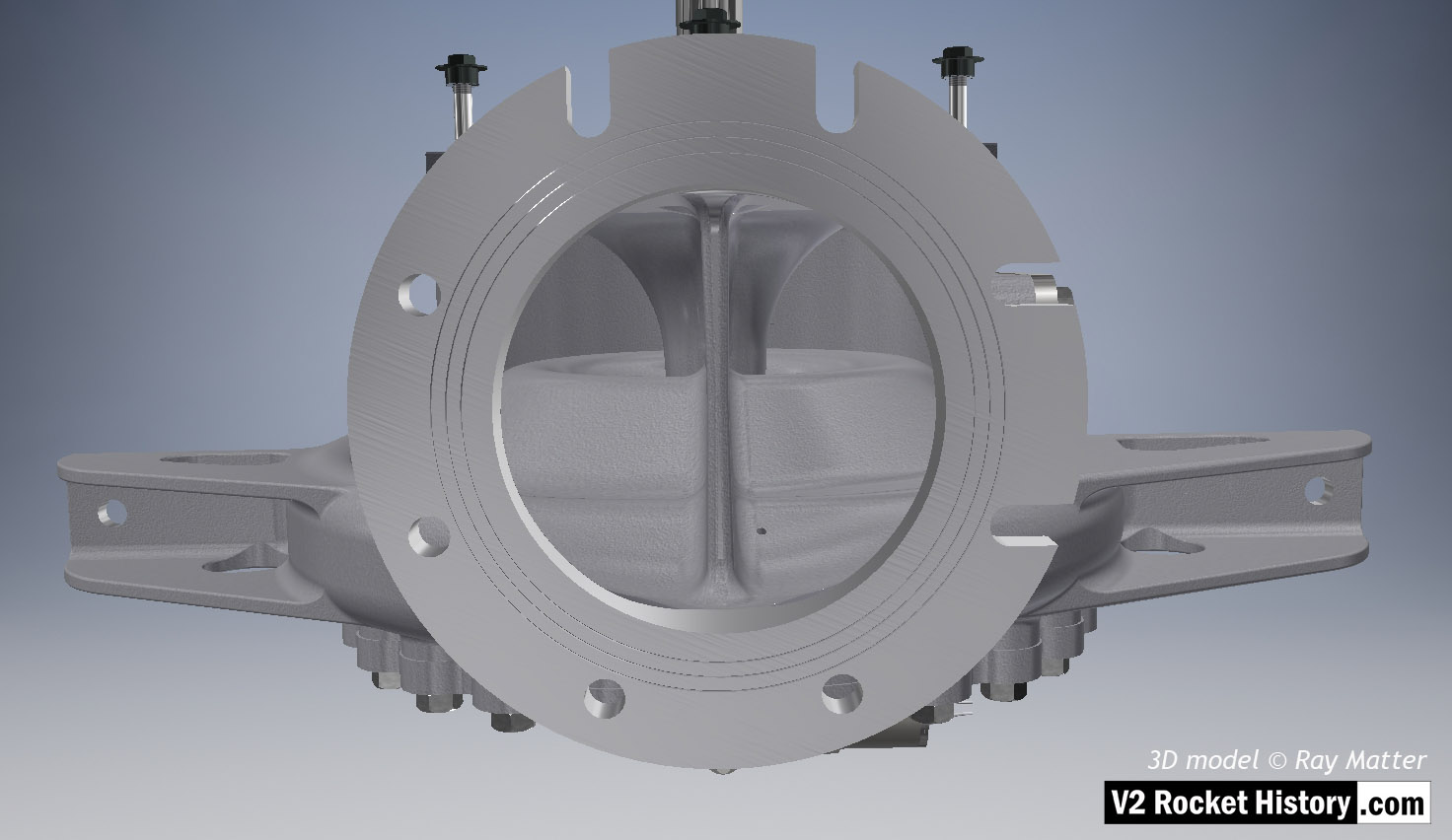
A (LOX) pump housing cutaway to reveal pump rotor side. The casing has been cut to show the internal rotor space detail. The outlet throat, right, and spiral volute space are displayed in this view as is the central LOX inlet. The web with the self-purge passageway can be seen on the outside center of the inlet throat, and connecting to the volute casing. The web or buttress seen to the upper right is to provide additional support between the structures whilst keeping the casting to an even density. 3D model Ray Matter
Close-up of 'A' LOX pump housing displaying cast and machined surfaces. LOX inlet aperture shown wand external threaded hole for manual bleed plug shown on far right. 3D model by Ray Matter
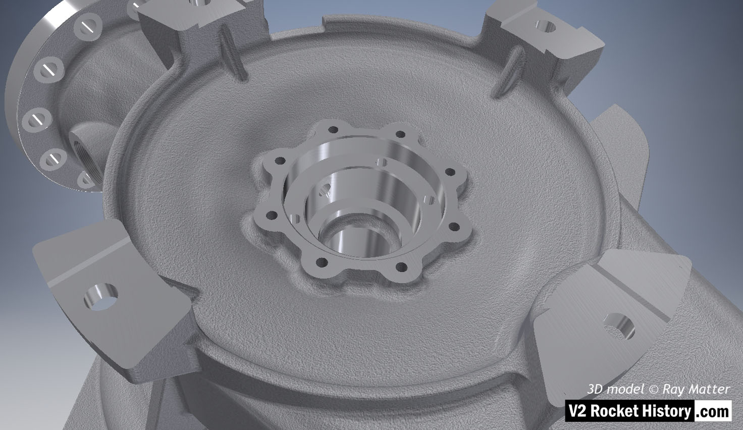
A (LOX) Pump sub-assembly, showing the face nearest the steam turbine. Single piece casting showing machined (milled) areas and detail of bearing and seal cavity. The four turbine case fitting brackets are displayed. 3D model Ray Matter
A-Pump LOX sub-assembly complete with face plate and fastenings as well as outlet throat plug. Shows square inlet throat blanking plate. 3D model Ray Matter
A (LOX) Pump sub-assembly, showing the face nearest the steam turbine. Turbine side of LOX pump showing flexible shaft connection disk (back component with 12 holes). The connection cavity drain pipe is shown (running across the outflow to the btm right). 3D model Ray Matter
Full assembly showing, from top, steam inlet ring manifold, LOX pump and portion of steam turbine assembly. View shows outlet flange facing camera. Note the three fine rings milled into flange face. The rings were designed to improve keying for the sealing 'putty' that was used to seal the connection between the flange face and the inlet pipe. 3D model Ray Matter
B-Pump Sub-assembly shown from top. View shows outlet flange facing camera - the splined drive shaft can just be seen at the top of the screen. Note the three fine rings milled into flange face.The rings were designed to improve keying for the 'putty' that was used to seal the connection between the flange face and the inlet pipe. Note, small self-purge orifice on the lower left of the inlet throat baffle. Unlike the upper purge hole in the LOX casing, the shallower face angle at the location of the hole in the fuel pump casing, was more accessible to drilling and was therefore not problematic. 3D model Ray Matter
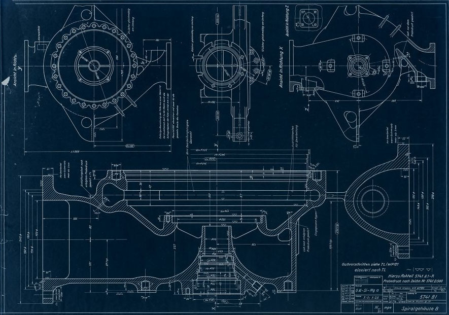
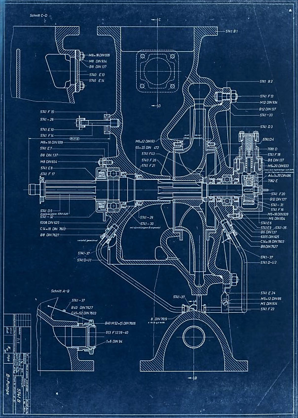
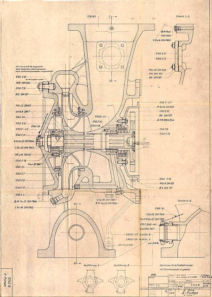
Drawing 5741 B - Fuel (B) Pump Assembly - Part Numbers
Drawing 5741 B - Fuel (B) Pump Assembly - Part Numbers
Drawing 5741 B mpe - Fuel (B) pump assembly showing part/drawing numbers. Drawing originates 20 July 1944 and revised with new number (AM41780) 16 Jan 1945. (Digipeer.de image)
Animation highlighting just one of many revisions to the turbo-pump that occurred at an accelerating rate between August 1943 and late 1944 as the missile moved from development to full production, and finally use in combat. (Digipeer.de images: animation RJD)
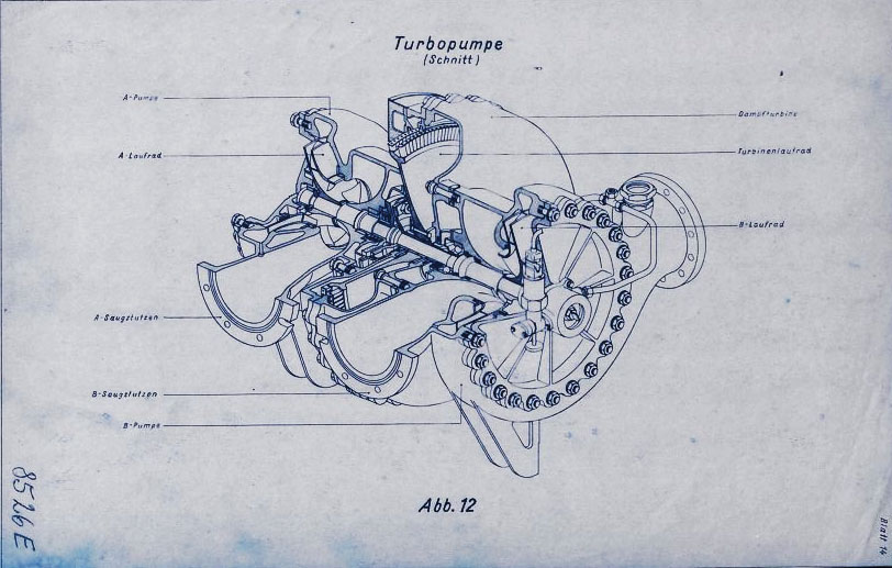
Sectioned general assembly view of the V2 turbo-pump (TP) dated September 1942. This image has been edited to show TP and document data closer together than the original.
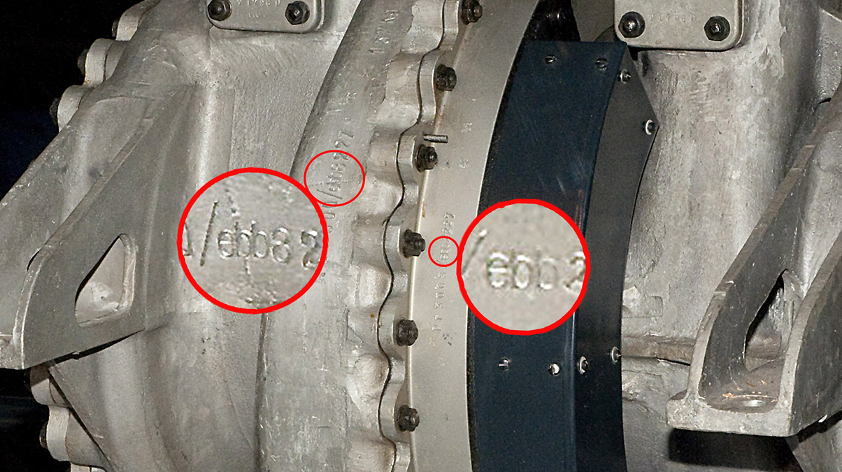
A complete V2 rocket turbo-pump on public display in the USA at the Smithsonian National Air and Space Museum in Washington DC showing Klein Schanzlin & Becker's wartime contractor armament code - ebb. Smithsonian National Air and Space Museum exhibit.
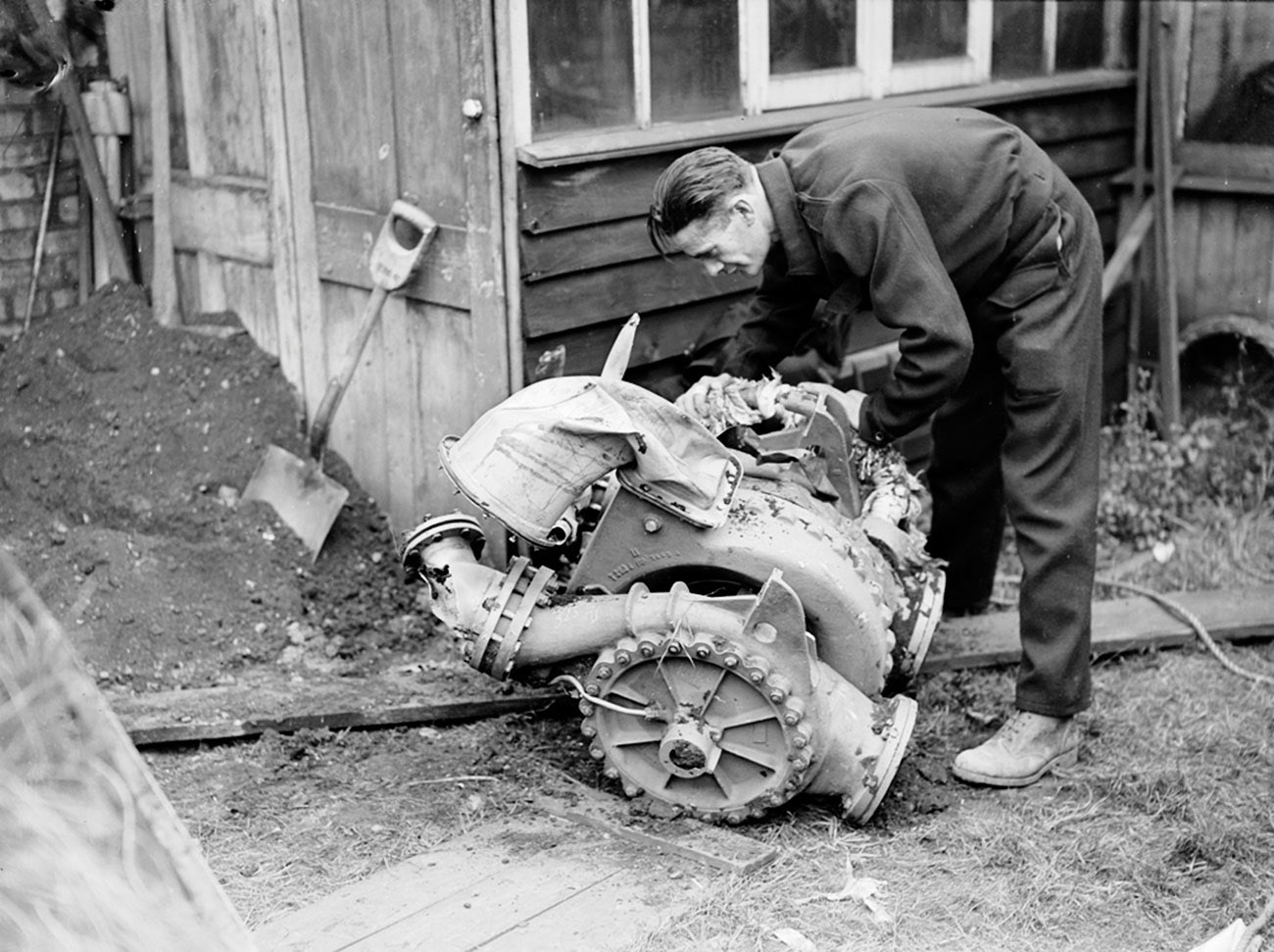
V2 rocket turbo-pump from a missile fired from Walcheren, Serooskerke, Vrederust, by battery no 444, at around 7am on September 17th 1944. The missile impacted East Ham with a direct hit on houses. Killing 6 people with 15 seriously injured. Much of the rocket debris was taken to the East Ham police station for examination by the military authorities. The serviceman in the picture is feeling the steam inlet manifold as it is still warm to the touch. Information porovided by www.v2rocket.com.
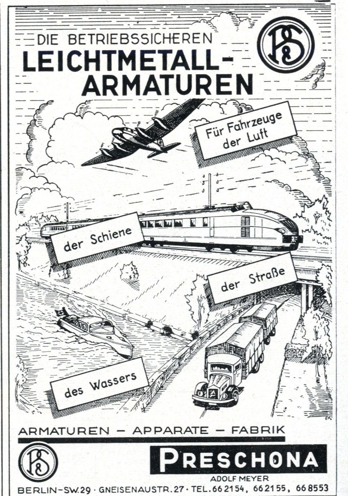
Trade literature advert for the Preschona company (Adolf Meyer) in Berlin, Germany. The company was a supply contractor and (among other items) manufactured the non-return valve for the steam turbine exhaust heat exchanger, employed to volatilise a small portion of liquid oxygen (LOX) to pressurise the LOX tank to maintain critical flow volume to the LOX turbo-pump.
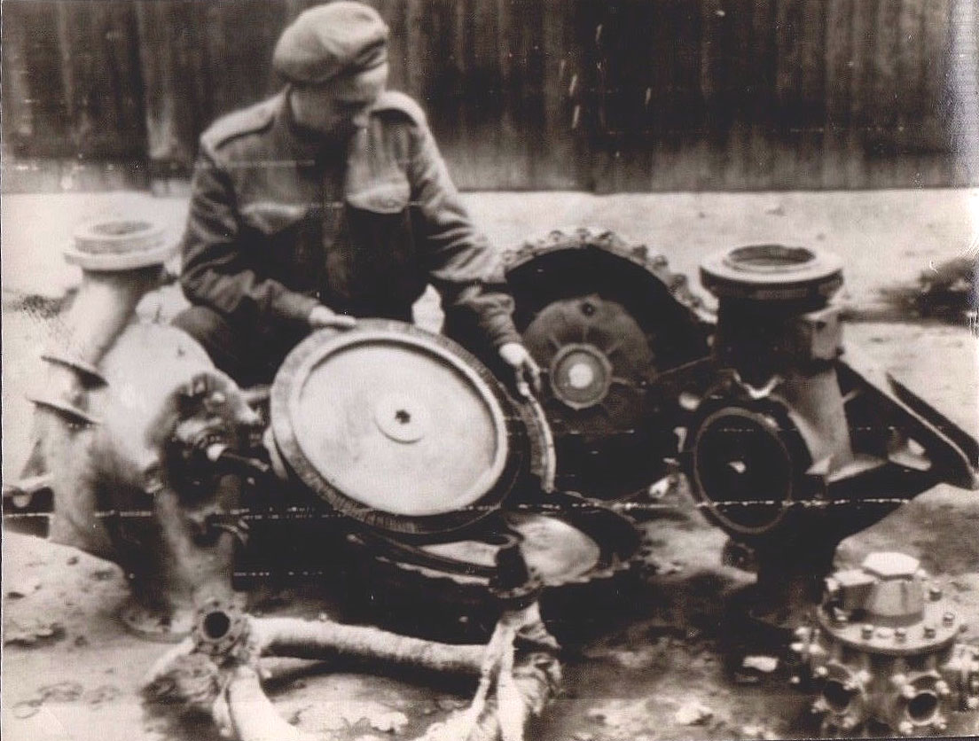
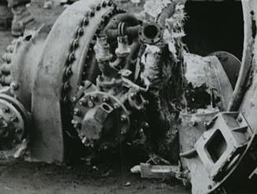
Image shows allied soldier examining remains of V2 rocket turbo-pump after impact. The soldier is holding the steam turbine rotor - the large size of this part is well shown in this photo. The still lagged steam inlet manifold can be seen in the left foreground and the LOX outlet manifold (and valve, topmost) can be seen in the lower right corner.
Picture shows tubo-pump debris from impact site. LOX manifold clearly seen (3 in 1 outlet pipes, upper center of image - the one to its right, 2 o'clock position, and left, 11 o'clock position are both broken off).The LOX flow electric control valve is also well displayed in this image (LOX valve head is slightly low and left of center, part nearest camera). The electrical connection to the LOX valve has broken away leaving its empty socket pointing upwards and to the right.
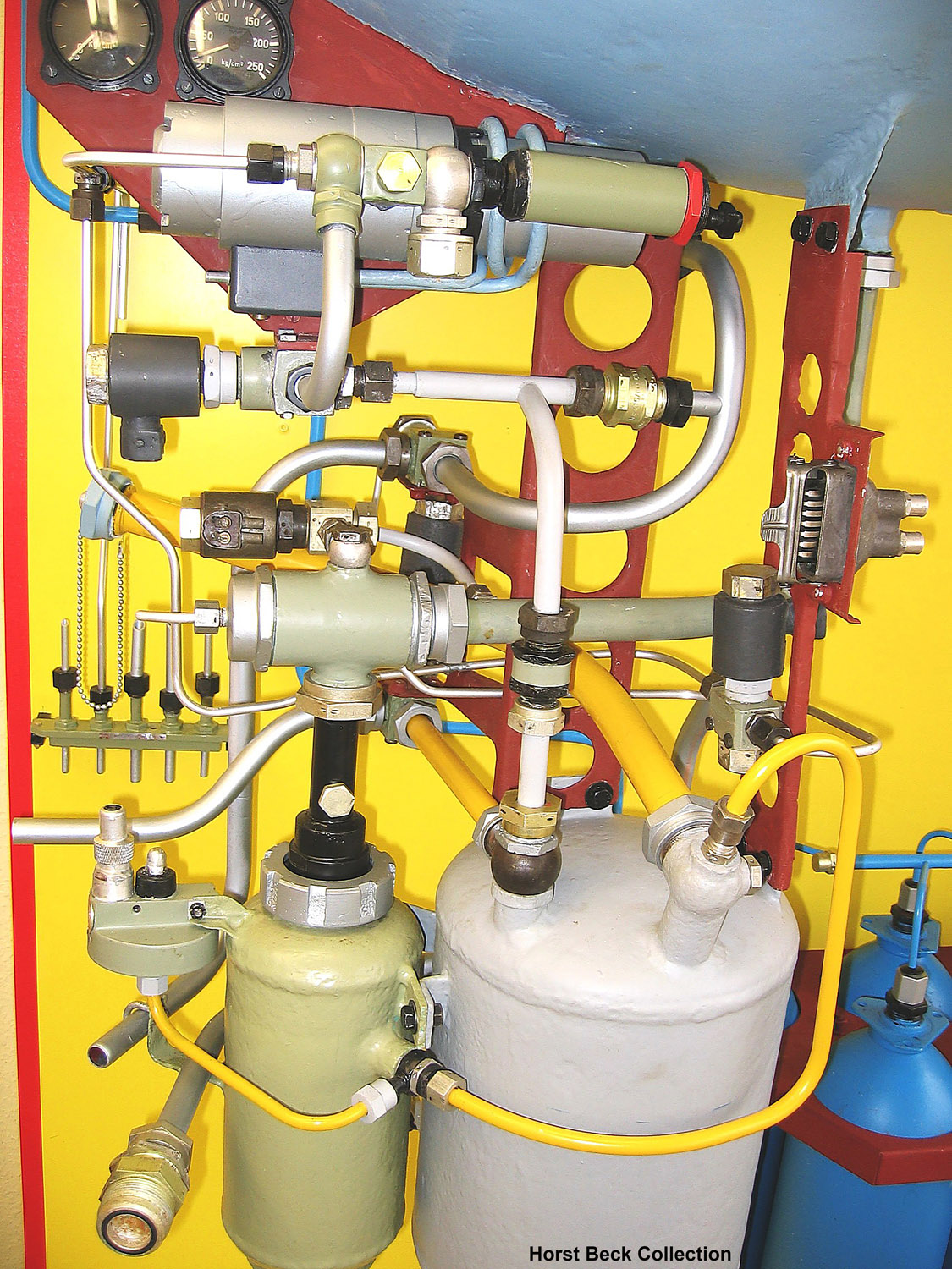
A4 missile steam generator detail. This excellent presentation was rebuilt from original refurbished parts by Horst Beck. See our video article The V2 Rocket Turbo-Pump for a technical exposition of the parts shown in this photo. Image courtesy The Horst Beck Collection
Early belt powered centrifugal pump by KSB with V2 TP features
Early belt powered centrifugal pump by KSB with V2 TP features
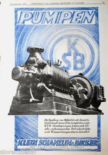
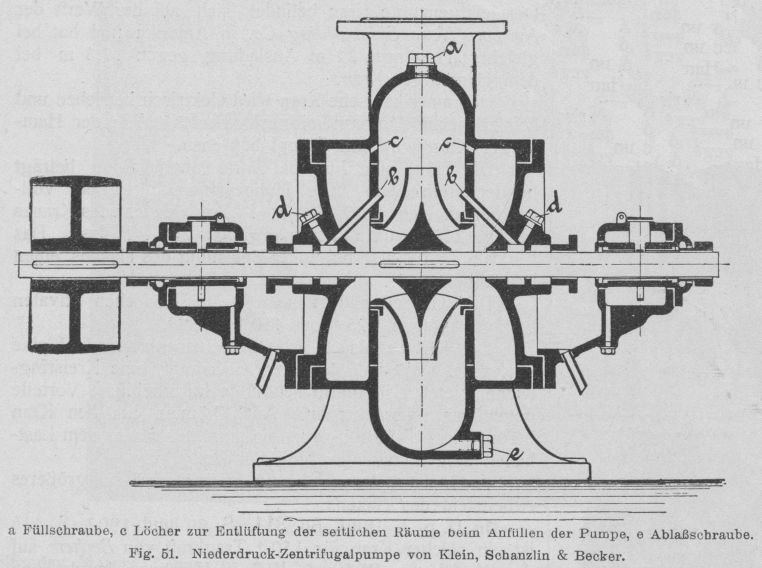
Early belt powered centrifugal pump by Klein Schanzlin & Becker. This schematic shows an early 20th century centrifugal pump designed and manufactured by KSB. The drawing appears to show auto-purge pathways at points marked C as well continuous lubrication pathways at B. Both of these important ideas would later feature in the propellant pump of the A4-V2 missile.
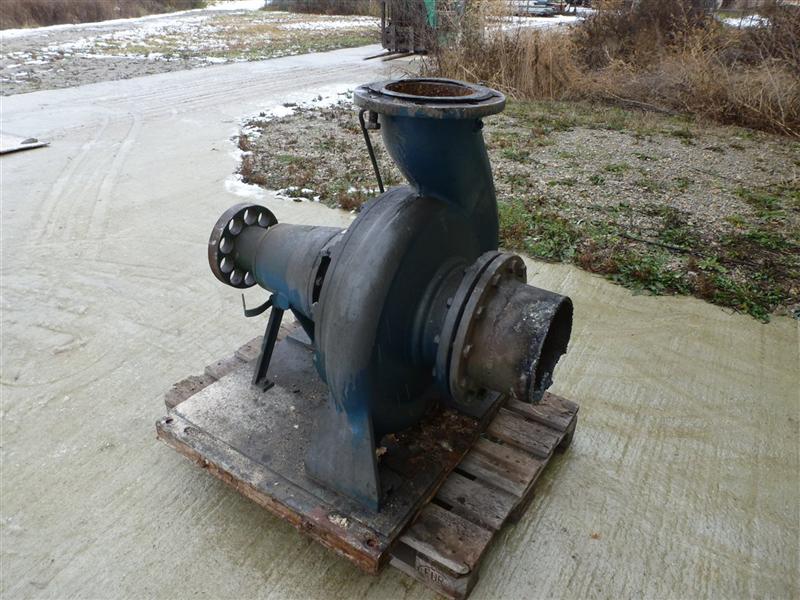
Family photo? Industrial volute case centrifugal pump by KSB
Family photo? Industrial volute case centrifugal pump by KSB
Large industrial volute case centrifugal pump by Klein Schanzlin & Becker. This image highlights the 'genetic'similarity and family resemblance between KSB's current and historical product range and the visible features of the A4-V2 missile Turbo-Pump (TP). Apart from the general shape of the cast spiral-volute case and its connection flanges, the 'soft' shaft connection (disk with holes on the extreme left of the pump) is very reminiscent of the semi-flexible shaft connection point linking one side the steam turbine rotor shaft to the shaft carrying a propellent pump rotor seen in the A4-V2 missile TP. Family photo? Industrial volute case centrifugal pump by KSB
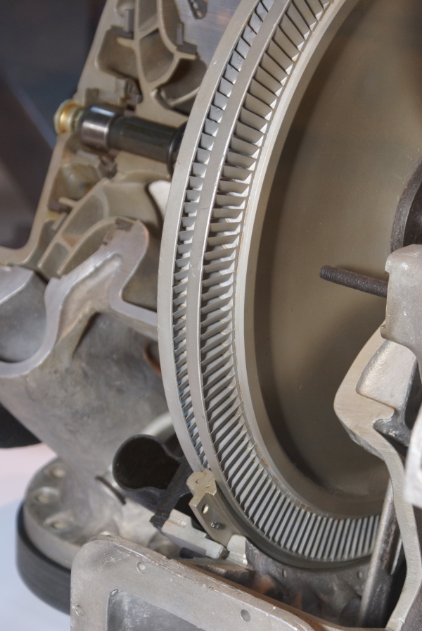
This image shows a cutaway of an A4-V2 turbo-pump. The section reveals the Curtis type 2-stage steam-turbine rotor and you can also see part of the stater inserted between the blades (bottom middle) and the adjacent steam distribution pipe (black open pipe on stater's immediate left). Top left, a centrifugal pump rotor can be seen - cut through, it shows a multi-splined shaft running through the centre, simple bearing and end-cap.
Family photo? Electric volute case centrifugal pump by KSB
Family photo? Electric volute case centrifugal pump by KSB
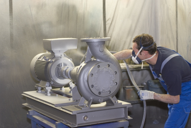
Electric industrial volute case centrifugal pump by Klein Schanzlin & Becker. This image highlights the 'genetic'similarity and family resemblance between KSB's current and historical product range and the visible features of the A4-V2 missile Turbo-Pump (TP). Assembly is shown being spray painted.
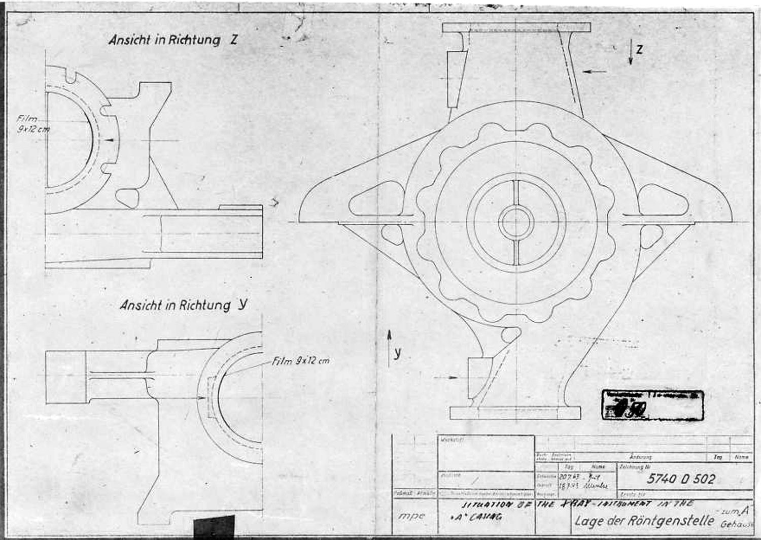
A Stoff (liquid oxygen) pump casing diagram showing stress points that require X ray quality control photography before use. The diagram shows the specific locations where photographic film is to be placed for X-ray analysis.
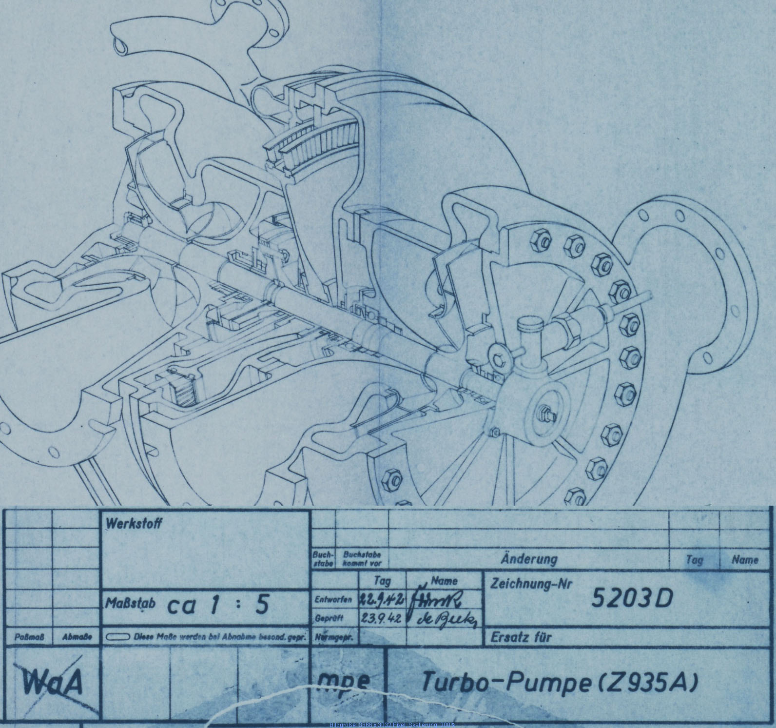
Turbo-Pump (Z 935 A) cutaway presentation Sept 1942
Turbo-Pump (Z 935 A) cutaway presentation Sept 1942
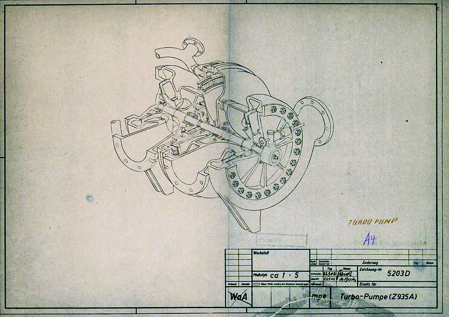
In this diagram the V2 Turbo-pump is shown in a cutaway presentation and rotated 90 degrees counter clockwise. The B stoff (fuel) pump is nearest the viewer - the over-speed device can be seen on the B stoff pump's case end-plate. The low pressure inlet ports our shown to the left, and high-pressure outlet ports are on the right. The steam distribution manifold can be seen at the furthest point from the viewer - the steam inlet pipe flange can also be seen. The feed pipe from the steam generator attaches to thus flange.
A4-V2 Steam rotor blade design and position 5742 B 1944
A4-V2 Steam rotor blade design and position 5742 B 1944
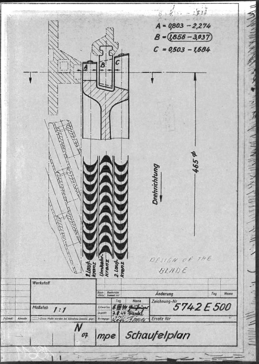
This mpe* drawing from 1945 shows the individual steam buckets or blades (labeled A and C) mounted to the rim of the rotor disk. As well as the fixed (i.e. stationary) stater blade B, positioned such that blades A & C can pass either side of it. The steam expansion is well shown by the increasing surface area of the blades from A to C, and growing larger, from left where the high pressure super heated steam enters the turbine, to right where it exits the blade pathway and passes in to the exhaust outlet. The lower graphic shows the way the super-heated high pressure steam is passed from the initial A blade and deflected by the reversed B stator blade for its energy to to be harvested for a second time by the C rotor blade. * mpe is the secret three letter armament code for Karlshagen, Werk Nord (North Works).
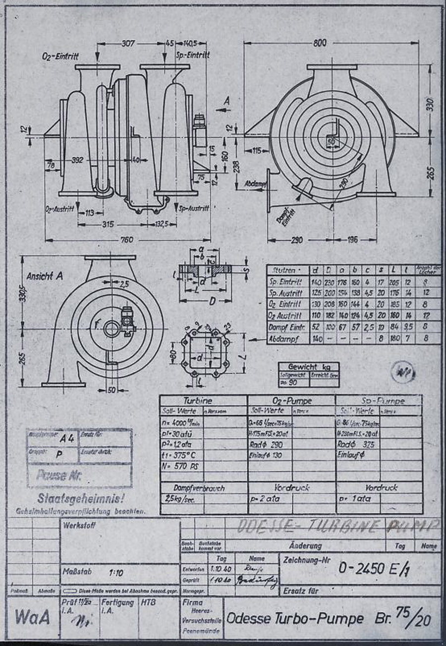
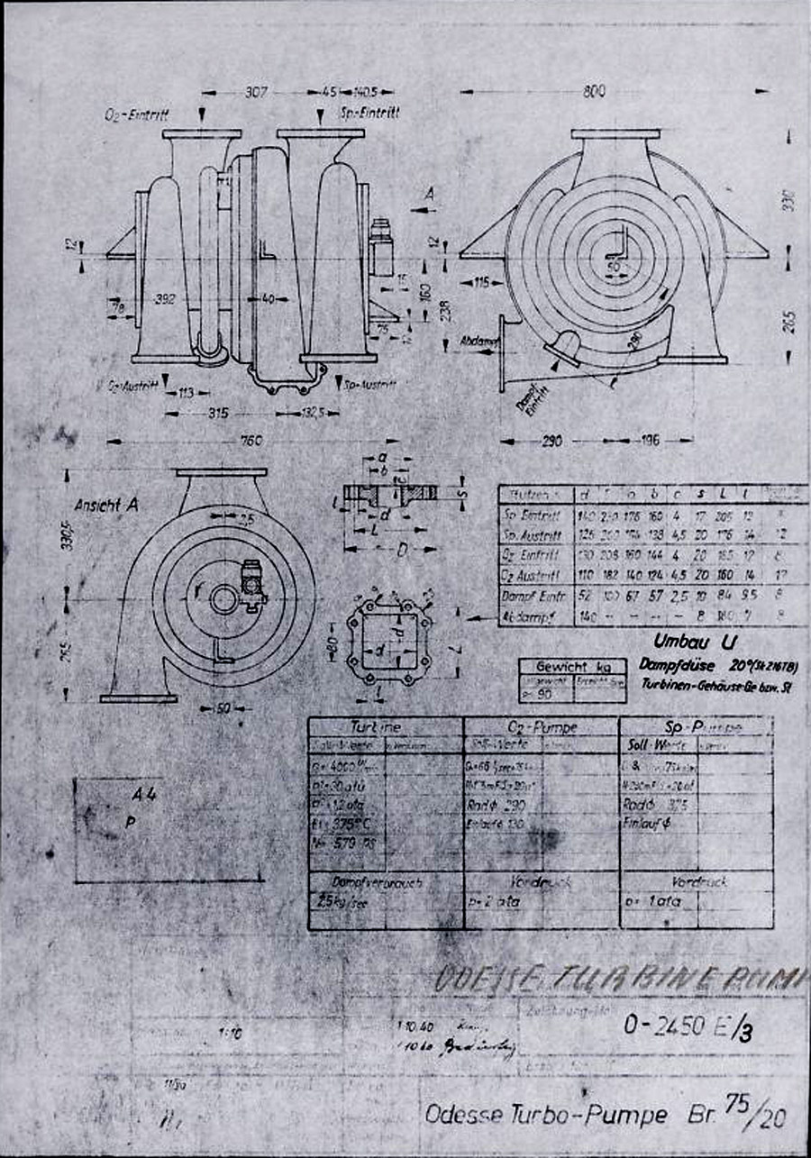
This HVP technical drawing from October 1940, shows a proposal from the Oddesse company - the full title of this company is KLEIN SCHANZLIN ODDESSE GmbH. Klein, Schanzlin & Becker A.G. (waffenamt code: ebb) took over Oddessa in 1929 and the company became formally known as KLEIN SCHANZLIN-ODDESSE GmbH (code ebc) in 1939. (NB: The company name has nothing to do with a similar sounding place name Odessa. The Oddesse trading name was formed from the partnership of English engineer Oddie, and German businessman Hesse.). The dual centrifugal turbo-pump shown in the drawing is a variant of a high pressure fire-fighting pump manufactured by Oddesse. Note the off-center outflow ports - not also that the outlet flanges are still level at this stage. Note also the incorrect spelling of the company name in the details panel lower right. (Digipeer.de image)
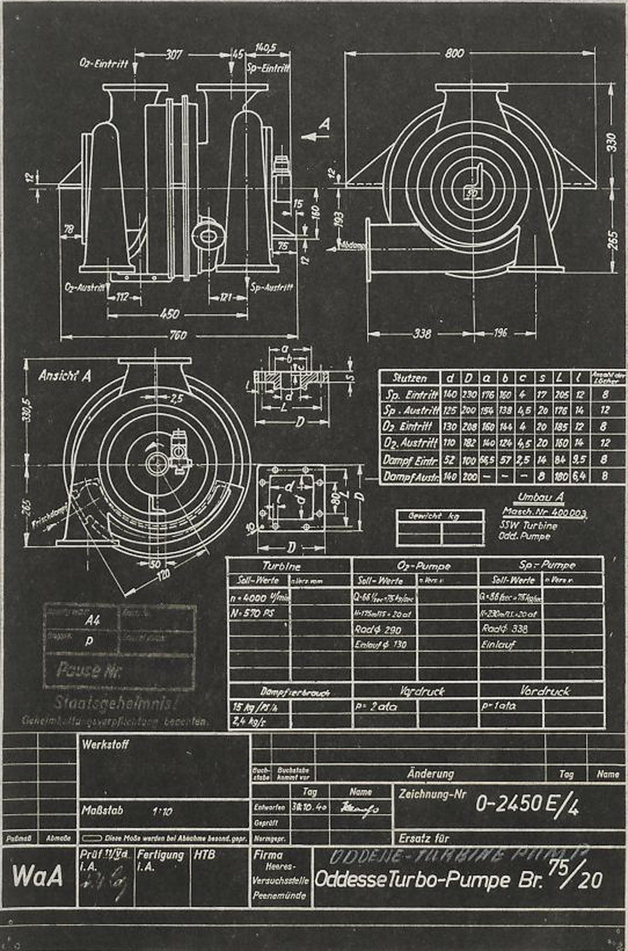
Another HVP technical drawing from later in October 1940, shows further data from the KLEIN SCHANZLIN ODDESSE (ebc) company A4-V2 turbo-pump project. See previous image for company details. The dual centrifugal turbo-pump shown in the drawing is a variant of a high pressure fire-fighting pump manufactured by Oddesse. Note the off-center outlet ports. Note also the corrected spelling of the company name in the details panel lower right (see previous Oddesse image) and the small note below the top table that indicates that the pumps are from Oddesse (ODD) and the turbine from a company indicated as SSW. (Digipeer.de image)
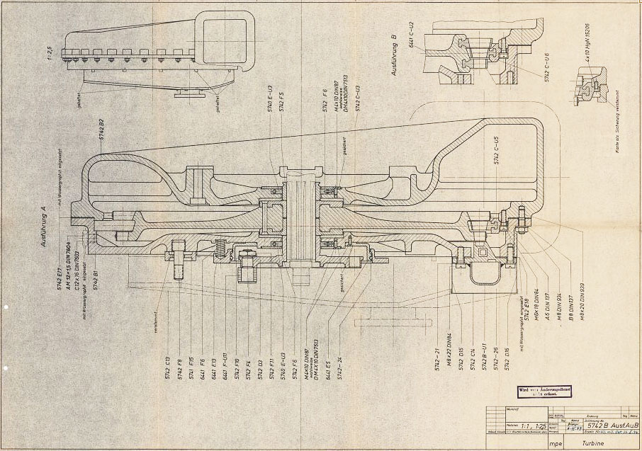
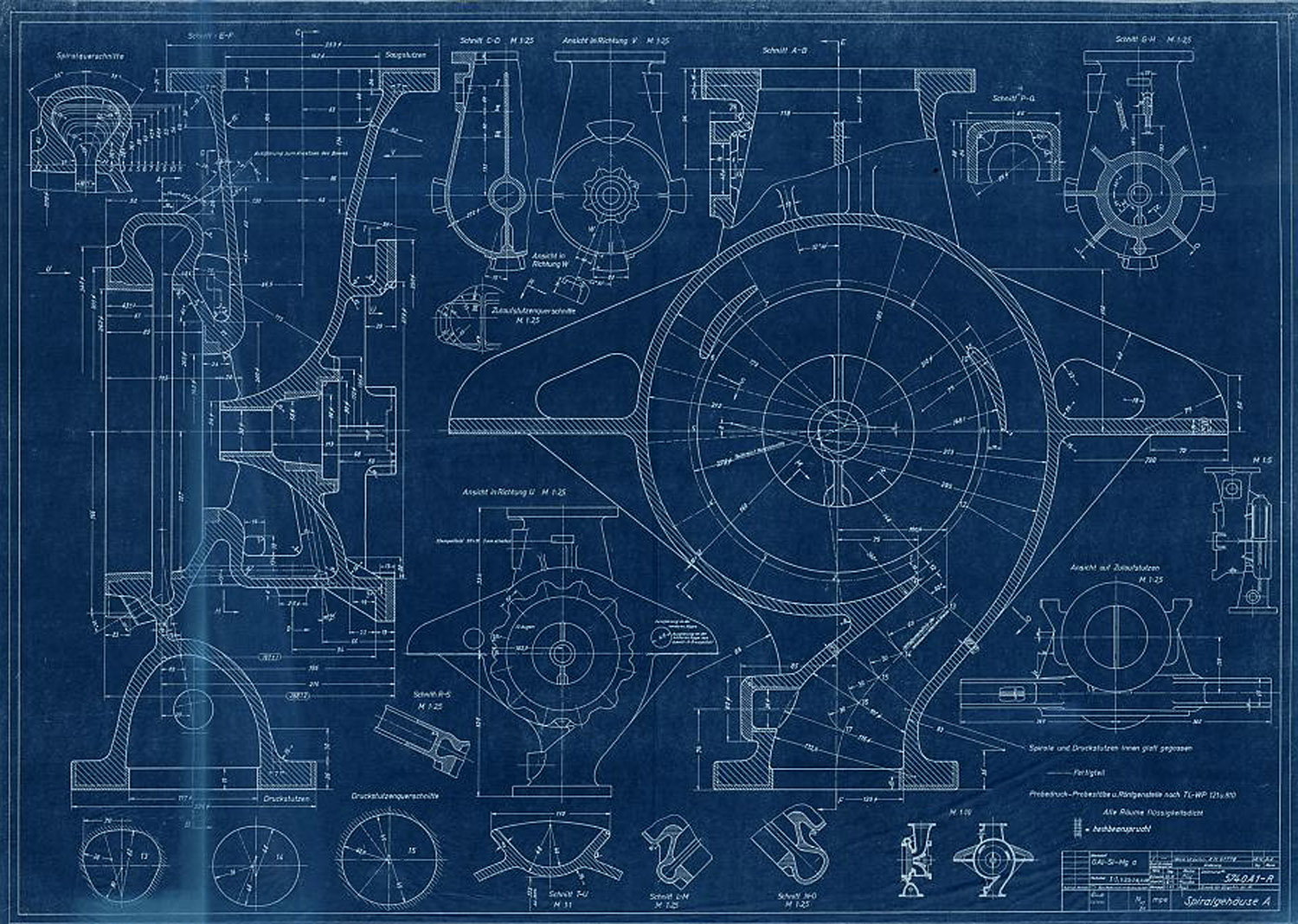
Turbopump Lieferfirma KSB, Frankenthal (vorläufiges Maßblatt Serie 0)
Turbopump Lieferfirma KSB, Frankenthal (vorläufiges Maßblatt Serie 0)
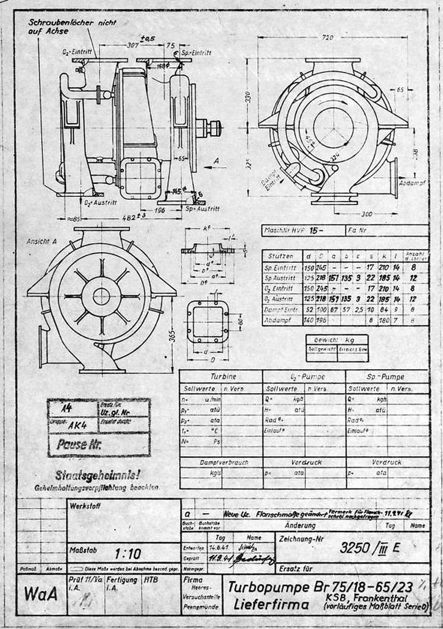
V2 rocket turbo-pump preliminary dimension sheet for O series, drawing. Many of the final elements of the turbo-pump design can be seen in this 'preliminary' drawing and table form 1941. The word lieferfirma in the data box btm right mean supply company - and this is indicated to be KSB or Klein Schanzlin & Becker AG, Frankenthal. Signatur FA 014/14769 (Digipeer.de image)
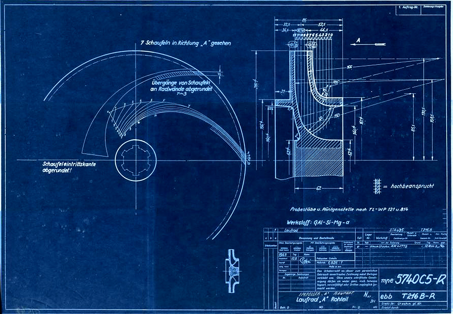
Laufrad A (Rohteil) zur A-Pumpe nach Zeichnungsnummer 5740 B Ausführung A und B [lt. Titelerfassung ...
Laufrad A (Rohteil) zur A-Pumpe nach Zeichnungsnummer 5740 B Ausführung A und B [lt. Titelerfassung ...
Centrifugal impeller for A or liquid oxygen (LOX) pump. The drawing originated in Aug 1943 and was superseded in December 1944. A key to the image hatching can be seen with the label 'Hochbeansprucht' which in English means Highly Stressed. Next to the drawing numbers two secret three letter armament codes can be seen indicating the 'origination' of the document. The top one mpe = Heimat Artillerie Park 11 (HAP or Army Artillery Range). The lower code ebb = Klein Schanzlin & Becker AG, Frankenthal. Signatur FA 014/02542 (Digipeer.de image)
A tutor in computer-aided design at Moscow State Technical University, Alexander Savochkin says he finds relaxation in transcribing 75-year-old missile plans into modern 3D CAD models. He lives with his very patient wife in the leafy suburbs of Moscow.