For more detailed images see the image gallery at the bottom of this post
The eighteen pot injector head.
This is the first image blog from Alexsander Savochkin in what we hope will become an expanding resource for those wishing to find out more about the design and construction of the A4/V2 missile. The precise 3D CAD model imagery is based exclusively on original drawings produced in Germany from 1940 to 1945. When enough material has been uploaded we will create a fixed menu item called ‘Anatomy of the V2‘ where we hope to be able to offer coverage of the entire missile in detailed 3D models like the ones shown here – Robert J. Dalby, editor in chief, V2 Rocket History.com
View of injector head showing liquid propellant (LOX and fuel) diffuser cups and head fuel valve seating ring at centre, (see other images for insert and position nomenclature). Visible immediately below the valve seat are the large connecting holes that allow fuel to flow from the inlet manifold and cooling jacket to the injector space (some brass injector inserts can be seen through the holes) after the head fuel valve is released to be opened by the turbo-pump supply pressure. The four veil cooling inlet connectors are well shown as are two of the outlet connection holes immediately above them. 3D model by Alexander SavochkinA close-up view of the head fuel valve mounting flange (showing 12 fastener holes). Visible immediately below the top flange are the large connecting holes that allow fuel to flow from the inlet manifold and cooling jacket to the injector space (some brass injector inserts can be seen through the holes) after the head fuel valve is released to be opened by the turbo-pump supply pressure.Inverted view of injector head showing liquid propellant (LOX and fuel) diffuser cups, (see other images for insert and position nomenclature). Of note in this image are the pointing angles of the cups, positioned on a parabolic section to focus the propellant nebular stream into the central axis of the combustion space. Also of note are the large areas between each cup NOT employed in the injection process leading to structured propellant mixing as opposed to even homogeneous mixing. The four veil cooling inlet connectors are well shown. 3D model by Alexander SavochkinUnderside view of injector head showing liquid propellant (LOX and fuel) diffuser cups, (see other images for insert and position nomenclature). Of note in this image are the pointing angles of the cups, positioned on a parabolic section to focus the propellant nebular stream into the central axis of the combustion space. Also of note are the large areas between each cup NOT employed in the injection process – initiating \’clumpy\’ and uneven propellant mixing initially below the injector face but also carried forward into the combustion space. The LOX spray head is shown in the centre of each cup. 3D model by Alexander SavochkinHere the 18-pot head model has been cut away to show the fuel cooling and fuel delivery spaces. the cooling jacket layer can be seen in the lowermost area of the head – below the centrally positioned fuel valve seat, between each cup at the lowest point, and running down toward the first set of veil cooling pores and the topmost coolant distributor ring. Note that the veil cooling system does not communicate with the regenerative cooling jacket and has its own feed pipes drawing fuel from the head injector space and not the cooling space. Visible immediately above the valve seat are the large connecting holes that allow fuel to flow from the inlet manifold and cooling jacket to the injector space after the head fuel valve is released to be opened by the turbo-pump supply pressure. 3D model by Alexander SavochkinClose-up detail showing independent pathway for fuel passing into injector head and fuel passed down from the head to be used for veil cooling system. Fig. A shows vertical passages for overall fuel feed to the head and Fig.B shows horizontal pathway for veil coolant fed from the head via the veil coolant distributor ring or manifold. 3D model by Alexander SavochkinLiquid propellant (LOX and fuel) diffuser cup, showing three rings or echelons (A, D,& E) of brass injector inserts as well as two rows of drilled fuel feed holes. The LOX spray head is shown in the centre. Note the simple ‘shower head or watering can’ design of the LOX diffuser. A sealing washer can be seen fitted between the LOX diffuser and the steel cup. 3D model by Alexander SavochkinView of the top of the injector head, with outer cups and pressed steel capping piece removed, showing, propellant diffuser inner cores with injector inserts and LOX supply pipe connection thread. The LOX spray head can be seen inside the LOX pipe connector. The swirl caps of fuel injector inserts in positions A, D,& E can be seen clearly on the outside of the cores and the two rows of drilled fuel feed holes are also well shown. 3D model by Alexander SavochkinGeneral view of the propellant diffuser cup inner core. The swirl caps of fuel injector inserts in positions A, D,& E can be seen clearly on the outside of the core as well as the central holes in the 3304D (red) inserts. The two rows of drilled fuel feed holes are also well shown. 3D model by Alexander Savochkin
Click the above video to see an animation of the diffuser cup inner core (the animation may take a few seconds to show at maximum resolution).
This image shows a burner cup from outer Ring I of the injector head and the cutaway shows injector insert echelon A, D, & E as well as two rows of drilled feed holes. Four fuel injector insert types can be seen: Top, A = 2131E, lower D, = 3303D (white), lowest E, = 3304D (red), and E, = 3305D (blue). 3D model by Alexander SavochkinCutaway showing echelon A with 2-part 2131E fuel injector inserts at the top of a propellant diffuser cup. Note the close proximity of the injector inserts to the simple ‘watering can’ type LOX spray head. One row of drilled fuel feed holes can be seen below the inserts. 3D model by Alexander SavochkinThis images shows a cutaway of a burner cup from outer Ring I of the injector head and shows injector insert echelon D, & E as well as one row of drilled feed holes. Three fuel injector insert types can be seen: Top D, = 3303D (white), lower E, = 3304D (red), and E, = 3305D (blue). 3D model by Alexander SavochkinOne of the 18 liquid propellants (LOX and fuel) diffuser cups, showing three rows or echelons (A, D,& E) of brass fuel injector inserts as well as two rows of drilled fuel feed holes. The LOX spray head is shown in the centre. 3D model by Alexander SavochkinExploded view showing some of the 1100 parts required for the complicated 18-pot injector head of the V2 25-ton thrust rocket engine. 3D model by Alexander Savochkin
The image gallery below has all the above pictures in higher resolution, some with additional text, as well as additional pictures not included in this post.
South Works 23-06-43
South Works 23-06-43
RAF reconnaissance photo showing the Werk Süd region with the F1 pre-production hall and to the north the IW repair and maintenance hall, centre right, and road rail links to Prüfstand XI (Test Stand 11, circular rampart centre left) heading directly left from F1. P-XI was conceived to provide engine test facilities for the nearby pre-production hall. Scroll down to see GPS map, the marker index is set to the centre of P-XI, click map and switch to satellite view and you will see that only a small section of the circular rampart remains visible. You can easily zoom out to cover the coast area where F1 and the equally large Repair & Maintenance Workshops are located. The area immediately surrounding P-XI is now contained within a commercial farming operation with sheep appearing to be the staple - or was anyway, at the time of our first visit to the vicinity in 2010 and our last in 2017 - none of the sheep seemed to recognise us though so they may have changed. (for access to restricted areas click here)
Picture shows parts of V2 missile fin structure laying on open ground near area between admin offices and F1 (near Admin. block railway platform, see map).
Picture shows metal debris within the F1 factory boundary walls. The purpose of the part buried liquid storage vessel in the foreground is unknown but it is not a vessel capable of being pressurised. Other assorted metal debris include pipe and cable wall cleats, as well as steel armature rods from reinforced concrete castings (powerful demolition explosions have freed the steel rods from the concrete). These reinforcement rods are a common sight in the environs of Fertigungshalle Eins (F1) and the nearby Repair & Maintenance Hall (R&MH).
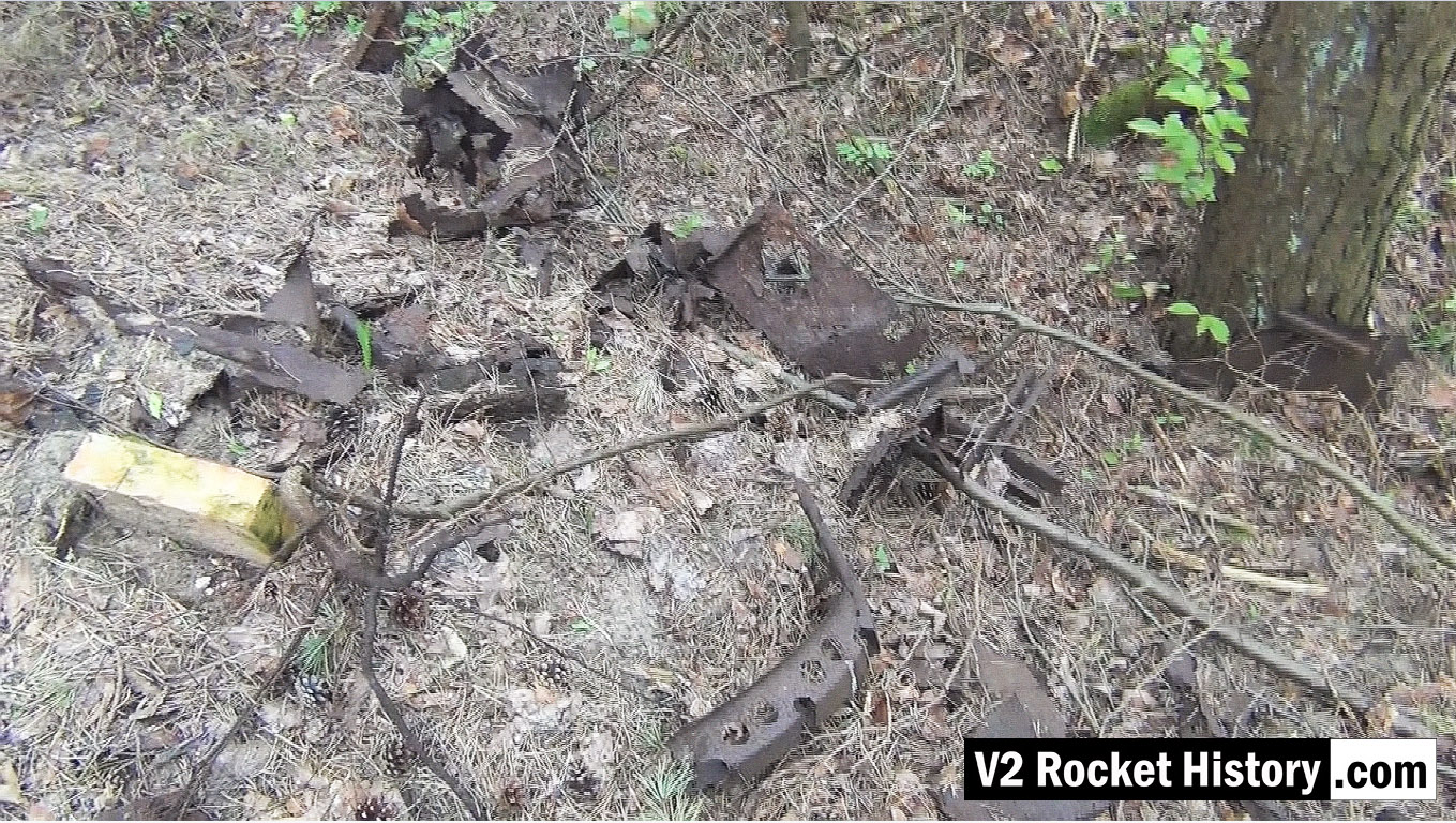
This picture shows a small debris field of steel fragments from the V2 missile 130m South-East of F1, and just 20m to the North East of the foundations of a small heat distribution building. Various body and frame parts can be seen and in the middle foreground a 350mm segment of curved missile body ring is visible. These parts have almost certainly been dug up and exposed by the action of metal detectorists. The metal fragments have been abandoned by their finders as they are perceived to have no financial value and hence are not worth removing from the site.
This picture shows a close up detail of parts in a small debris field of steel fragments from the V2 missile 130m South-East of F1, and just 20m to the North East of the foundations of a small heat distribution building. Various body and frame parts can be seen and in the upper left and two segments of curved missile body ring are visible. See previous.
Wooden carboy frame from WW2 (possibly used for transporting small quantities of corrosive and dangerous liquids employed in the V2 steam plant, (such as T-Stoff) laying among trees 190m East of F1 in a location used as an emergency rail freight loading area to F1 due to damage caused by US air raids in August 1944.
Wooden carboy frame from WW2 (possibly used for transporting small quantities of corrosive and dangerous liquids employed in the V2 steam plant (such a T-Stoff) laying among trees 190m East of F1 in a location used as an emergency rail freight loading area for F1 due to damage caused to rail track by US air raids in August 1944.
This picture shows Robert Dalby collecting GPS data with a mapping camera just North of the East end of the Admin office rail platform (near the ruins of the small admin/F1 heat distribution hub building). In all of our explorations we routinely collect GPS track and data points to be able to accurately locate finds and establish a precise correlation between areas of interest identified on historical reconnaissance photography and the modern ground terrain. In the picture Robert is pointing a Contour video camera at details of the terrain that automatically captures the camera's GPS location information. This data can then be combined with satellite imagery, via Google maps, and provide a detailed graphic mapping track alongside the video footage.
Oil storage shed - cut down vertical girder with door hanger
Oil storage shed - cut down vertical girder with door hanger
Photo shows the cut stump of an heavy upright support girder. The ragged profile of the cut shows that it has been cut down with an oxygen and gas torch or possibly a larger fuel and oxygen device like a thermal lance. The steel support still has the bottom support pin for a large door. Note that although the girders have been gas-cut there is a great deal of mechanical damage to the steel work that was not caused by the cutting work. Considerable force would be required to bend the middle girder in the way shown, even if it was much longer at the time the bend was created. The upper superstructure of the storage shed may have been part demolished using a bulldozer. Or perhaps the East German Army may have used the site for explosives training - signs of demolition explosive use are in evidence nearby. The map under the album presentation of this picture shows the exact location of the girders.
A tutor in computer-aided design at Moscow State Technical University, Alexander Savochkin says he finds relaxation in transcribing 75-year-old missile plans into modern 3D CAD models. He lives with his very patient wife in the leafy suburbs of Moscow.