For more detailed images see the image gallery at the bottom of this post
The eighteen pot injector head.
This is the first image blog from Alexsander Savochkin in what we hope will become an expanding resource for those wishing to find out more about the design and construction of the A4/V2 missile. The precise 3D CAD model imagery is based exclusively on original drawings produced in Germany from 1940 to 1945. When enough material has been uploaded we will create a fixed menu item called ‘Anatomy of the V2‘ where we hope to be able to offer coverage of the entire missile in detailed 3D models like the ones shown here – Robert J. Dalby, editor in chief, V2 Rocket History.com
View of injector head showing liquid propellant (LOX and fuel) diffuser cups and head fuel valve seating ring at centre, (see other images for insert and position nomenclature). Visible immediately below the valve seat are the large connecting holes that allow fuel to flow from the inlet manifold and cooling jacket to the injector space (some brass injector inserts can be seen through the holes) after the head fuel valve is released to be opened by the turbo-pump supply pressure. The four veil cooling inlet connectors are well shown as are two of the outlet connection holes immediately above them. 3D model by Alexander SavochkinA close-up view of the head fuel valve mounting flange (showing 12 fastener holes). Visible immediately below the top flange are the large connecting holes that allow fuel to flow from the inlet manifold and cooling jacket to the injector space (some brass injector inserts can be seen through the holes) after the head fuel valve is released to be opened by the turbo-pump supply pressure.Inverted view of injector head showing liquid propellant (LOX and fuel) diffuser cups, (see other images for insert and position nomenclature). Of note in this image are the pointing angles of the cups, positioned on a parabolic section to focus the propellant nebular stream into the central axis of the combustion space. Also of note are the large areas between each cup NOT employed in the injection process leading to structured propellant mixing as opposed to even homogeneous mixing. The four veil cooling inlet connectors are well shown. 3D model by Alexander SavochkinUnderside view of injector head showing liquid propellant (LOX and fuel) diffuser cups, (see other images for insert and position nomenclature). Of note in this image are the pointing angles of the cups, positioned on a parabolic section to focus the propellant nebular stream into the central axis of the combustion space. Also of note are the large areas between each cup NOT employed in the injection process – initiating \’clumpy\’ and uneven propellant mixing initially below the injector face but also carried forward into the combustion space. The LOX spray head is shown in the centre of each cup. 3D model by Alexander SavochkinHere the 18-pot head model has been cut away to show the fuel cooling and fuel delivery spaces. the cooling jacket layer can be seen in the lowermost area of the head – below the centrally positioned fuel valve seat, between each cup at the lowest point, and running down toward the first set of veil cooling pores and the topmost coolant distributor ring. Note that the veil cooling system does not communicate with the regenerative cooling jacket and has its own feed pipes drawing fuel from the head injector space and not the cooling space. Visible immediately above the valve seat are the large connecting holes that allow fuel to flow from the inlet manifold and cooling jacket to the injector space after the head fuel valve is released to be opened by the turbo-pump supply pressure. 3D model by Alexander SavochkinClose-up detail showing independent pathway for fuel passing into injector head and fuel passed down from the head to be used for veil cooling system. Fig. A shows vertical passages for overall fuel feed to the head and Fig.B shows horizontal pathway for veil coolant fed from the head via the veil coolant distributor ring or manifold. 3D model by Alexander SavochkinLiquid propellant (LOX and fuel) diffuser cup, showing three rings or echelons (A, D,& E) of brass injector inserts as well as two rows of drilled fuel feed holes. The LOX spray head is shown in the centre. Note the simple ‘shower head or watering can’ design of the LOX diffuser. A sealing washer can be seen fitted between the LOX diffuser and the steel cup. 3D model by Alexander SavochkinView of the top of the injector head, with outer cups and pressed steel capping piece removed, showing, propellant diffuser inner cores with injector inserts and LOX supply pipe connection thread. The LOX spray head can be seen inside the LOX pipe connector. The swirl caps of fuel injector inserts in positions A, D,& E can be seen clearly on the outside of the cores and the two rows of drilled fuel feed holes are also well shown. 3D model by Alexander SavochkinGeneral view of the propellant diffuser cup inner core. The swirl caps of fuel injector inserts in positions A, D,& E can be seen clearly on the outside of the core as well as the central holes in the 3304D (red) inserts. The two rows of drilled fuel feed holes are also well shown. 3D model by Alexander Savochkin
Click the above video to see an animation of the diffuser cup inner core (the animation may take a few seconds to show at maximum resolution).
This image shows a burner cup from outer Ring I of the injector head and the cutaway shows injector insert echelon A, D, & E as well as two rows of drilled feed holes. Four fuel injector insert types can be seen: Top, A = 2131E, lower D, = 3303D (white), lowest E, = 3304D (red), and E, = 3305D (blue). 3D model by Alexander SavochkinCutaway showing echelon A with 2-part 2131E fuel injector inserts at the top of a propellant diffuser cup. Note the close proximity of the injector inserts to the simple ‘watering can’ type LOX spray head. One row of drilled fuel feed holes can be seen below the inserts. 3D model by Alexander SavochkinThis images shows a cutaway of a burner cup from outer Ring I of the injector head and shows injector insert echelon D, & E as well as one row of drilled feed holes. Three fuel injector insert types can be seen: Top D, = 3303D (white), lower E, = 3304D (red), and E, = 3305D (blue). 3D model by Alexander SavochkinOne of the 18 liquid propellants (LOX and fuel) diffuser cups, showing three rows or echelons (A, D,& E) of brass fuel injector inserts as well as two rows of drilled fuel feed holes. The LOX spray head is shown in the centre. 3D model by Alexander SavochkinExploded view showing some of the 1100 parts required for the complicated 18-pot injector head of the V2 25-ton thrust rocket engine. 3D model by Alexander Savochkin
The image gallery below has all the above pictures in higher resolution, some with additional text, as well as additional pictures not included in this post.
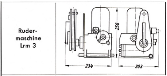
Askania rudder servo 'Rudermaschine LRM 3'
Askania rudder servo 'Rudermaschine LRM 3'
A schematic drawing of the Askania rudder servo 'Rudermaschine LRM 3'showing the critical compact dimentions of the device making it ideal for retro fit projects for smaller aircraft.
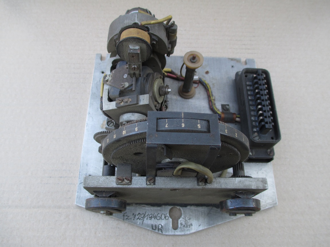
LEV-3 Horizont and Vertikant gyroscope system 1940
LEV-3 Horizont and Vertikant gyroscope system 1940
LEV-3 V2 missile gyroscope system with mounting plate. The third component of this system, the Muller gyroscopic accelerometer, is missing - the 2x mounting points can be seen on the right-hand side of the mounting plate.
Photo shows rare surviving complete set of 8 lead acid battery cells from one of the V2 rocket's 32 volt (100 amp) lead acid batteries. Two sets of batteries like this were used to provide the direct current (DC) voltage used aboard the V2 missile to power the DC to 3-phase alternating current (AC) generators, that in turn, powered the gyroscopes, electro-hydraulic servos, trim motors and other vital guidance and control devices. Photo copyright: The Horst Beck Collection
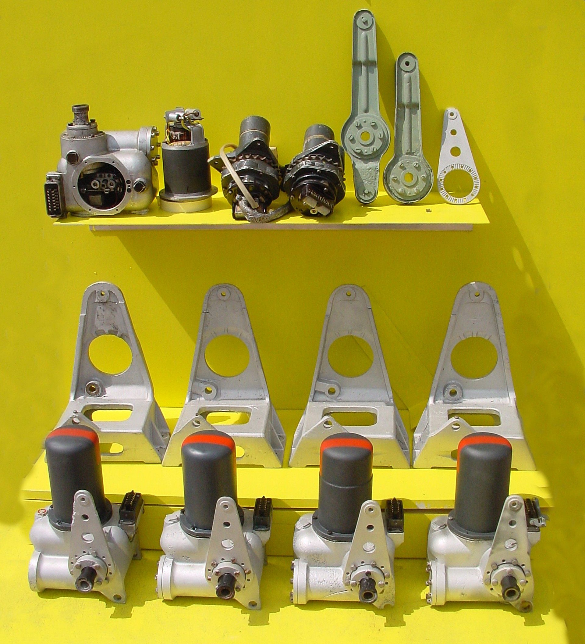
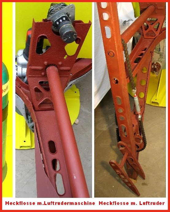
Photo shows a unique display at the Horst Beck Collection (HBC). Over many years Mr Horst Beck has painstakingly acquired and restored many A4-V2 missile parts - and in some cases, reassembled them into complete sub-assemblies. Shown here is part of the collection's hydraulic servos and trim motor parts display. In the foreground we see four hydraulic servos, and behind them their A frame mounting 'chairs'. The top shelf, from left to right, shows a servo with motor removed (and placed on its right). In the middle, two trim motors and chain sprocket gear-boxes for the aerodynamic trim surfaces on the trailing edge tips of fins 2 and 4. Next the pale green crank levers, the first longer one is for the hydraulic servo that controls the jet vanes and trimmers on fins 1 and 3. The shorter version minus the top horn, is used on the servos for fins 2 and 4. The last, silver coloured item,os a servo stabiliser (all the servos shown have one already fitted). Photo copyright: The Horst Beck Collection
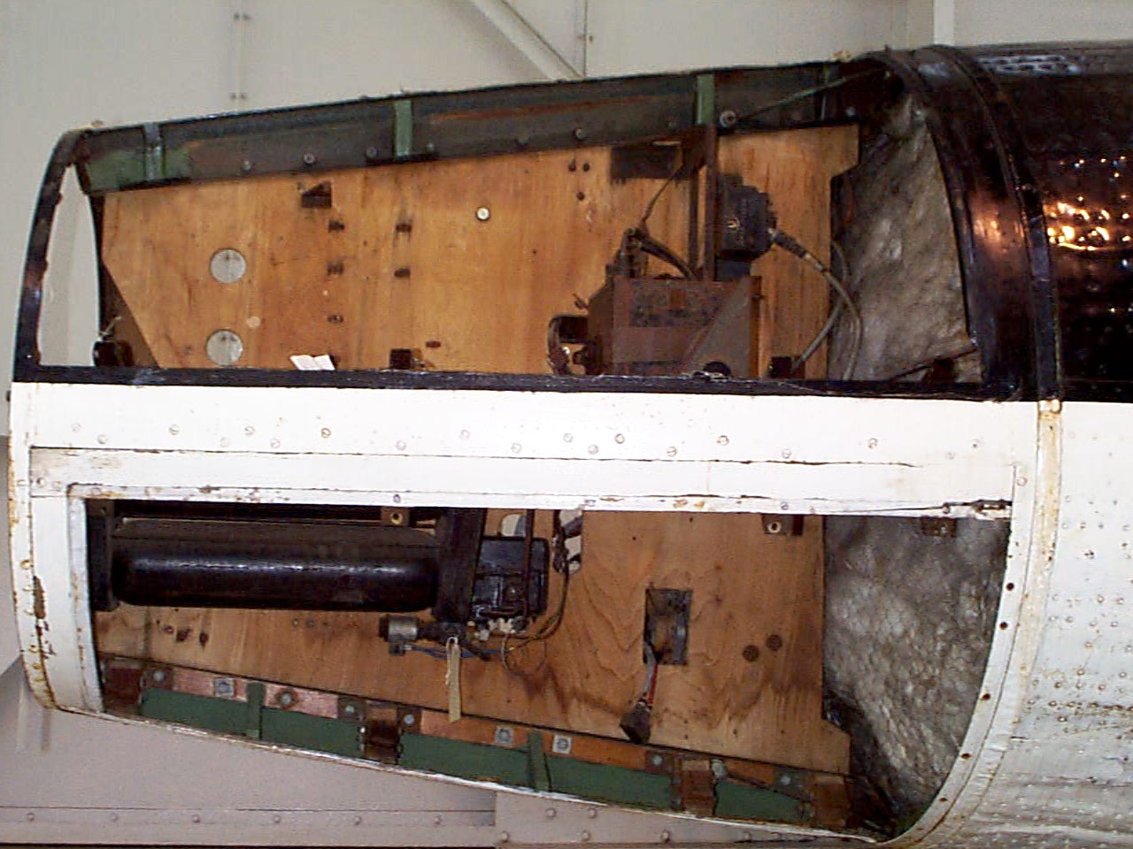
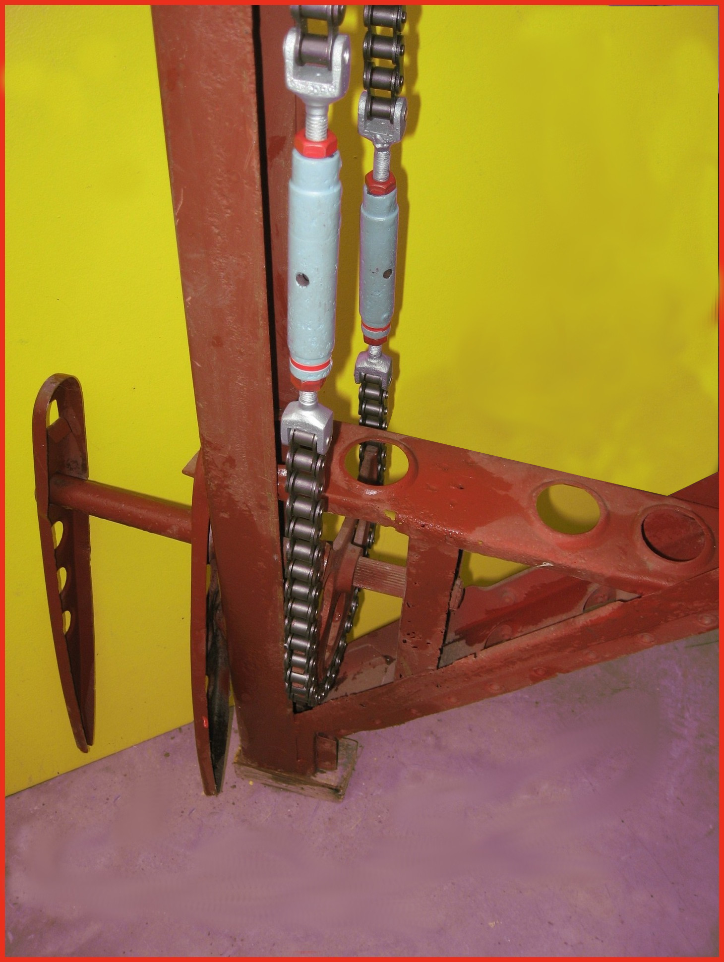
Photo shows restored air-rudder and fin detail. The grey painted barrel-strainers are both adjusted independently to reduce slack in the drive chain and avoid introducing a deflection bias in the air rudder. The 1.9kg counterbalance weight normally located at the top of the trim fin (or air rudder) is missing in this presentation. This excellent restoration is the work of Horst Beck. Photo copyright: The Horst Beck Collection
Detail of fin 2 or 4 showing trim motor and drive chain
Detail of fin 2 or 4 showing trim motor and drive chain
Photo shows partially restored air-rudder and fin detail. The image on the left shows the relationship of the trim motor to the air rudder drive shaft on fins 2 and 4. A chain similar in gauge to the type used on a push-bike and yet, at the other end of the shaft, the chain transmitting the torque of the trim motor to the air-rudder drive sprocket has a heavy gauge chain similar to that found on a 1000CC motor-cycle! This excellent restoration is the work of Horst Beck. Photo copyright: The Horst Beck Collection
Photo shows four restored graphite jet vane support blocks and bearing housings. The round plates we can see here act as heat sinks and allow heat to radiate away from the support block and bearing to help prevent expansion due to relatively rapid and uneven temperature distribution accumulation. The graphite vanes were quite brittle and cracking caused by rapid and uneven expansion could cause the vane to disintegrate. The area around the graphite vanes was exposed to the accumulation of heat not merely as a result of duration of the motor burn time but temperature was also increased at higher rates as the jet plume expanded with the decreasing atmospheric pressure as the missile gained altitude. This excellent restoration is the work of Horst Beck. Photo copyright: The Horst Beck Collection
Photo shows rare surviving 1.2 volt cell from the V2 missile's 50 volt command or signalling battery used in its gyro guidance system (note, the terminal connection on the left is missing from this exhibit, it would be identical to the one on the right). This wet nickel-cadmium battery cell was combined in pairs to a total set of 21 providing a 50.4 voltage at 300mA. The cells were contained in a wooden box that was held on a rack in equipment bay III. Its function was to provide the direct current (DC) signalling voltage that communicated the moment to moment resistance of the gyroscope's potentiometers to the analog guidance computer (Mischgerät = Mixer-device or control amplifier) aboard the V2 missile. It was critical that the signalling voltage was maintained between 48 and 50.4 volts. Photo copyright: The Horst Beck Collection
Impact wreckage of electro-hydraulic jet vane servo
Impact wreckage of electro-hydraulic jet vane servo
Wreckage of hydraulic servo from fin 2 or 4 of V2 missile that fell on a farm in Essex in March 1945. The motor has been removed and we can see details of the oil gear pump and valve control gear. The 3 position electromagnetic relay switch is visible at the 7 to 8 o'clock position within the open aperture. The push rod that connects the relay to the gear pump valves is also visible as a short brown coloured rod with a fine wire connector at each end, running in towards the gear-valves from the 9 o'clock position. The point that provides electrical current for the motor (which runs all the time and in one direction only) can be seen at the three o'clock position. The black housing has two sets of brass tongues that receive the matching brass spades mounted on the base of the motor for power input. The motor drive shaft has a female square socket coupling to connect the motor to the middle drive gear of the gear pump. A small portion of the square drive shaft of the central gear can just be seen in the photo - in the centre of the valve control block.
The J device no1 (J Gerate Eins). The full name of this device is: the Muller Pendulous (or mechanical) Integrating Gyroscopic Accelerometer - today normally referred to as a PIGA. The device, designed by Fritz K Muller, operates as a switch to initiate rocket engine shutdown and is able to smoothly record and accumulate every moment of acceleration, without any kind of recording resolution or discrete time interval limit, of the rocket's entire motor burn phase, and at the same time process this accumulated acceleration with respect to time as a gradually increasing velocity. In the case of the V2 missile, when the correct predetermined velocity is reached, the velicity sufficient to achieve the desired range of the missile, the device trips the relays that close valves that shutdown the supply of steam to the turbo-pump, and thus shutdown the rocket motor itself.
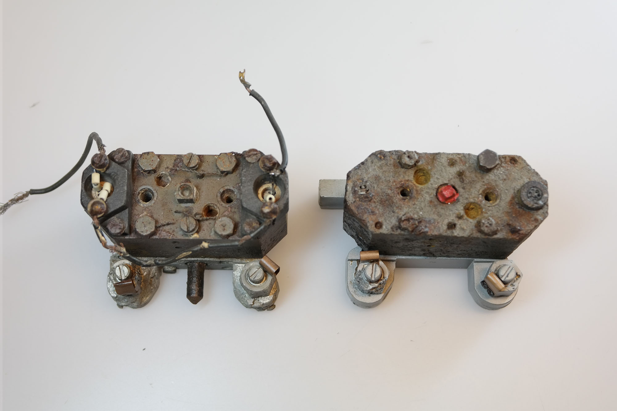
Two Askania (designed) hydraulic gear pumps - the examples shown here have two ceramic insulators with with Nichrome wire type heating elements. The heaters are located at each end of the pump on the long axis. The pump on the right still has its power supply wires attached and was easily repaired and restored to full function in our workshop.This type of pump (with heaters) seem to be rare among the debris of European combat impact sites but fairly common in debris collections emanating from research flights in Peenemünde and parts of Poland. An explanation maybe that the oil could be warmed up sufficiently simply by starting all four hydraulic gear pumps sooner in the pre-launch sequence. The only downside being that the already noisey missile would be making yet more noise in the risky period leading up to launch.
A tutor in computer-aided design at Moscow State Technical University, Alexander Savochkin says he finds relaxation in transcribing 75-year-old missile plans into modern 3D CAD models. He lives with his very patient wife in the leafy suburbs of Moscow.