For more detailed images see the image gallery at the bottom of this post
The eighteen pot injector head.
This is the first image blog from Alexsander Savochkin in what we hope will become an expanding resource for those wishing to find out more about the design and construction of the A4/V2 missile. The precise 3D CAD model imagery is based exclusively on original drawings produced in Germany from 1940 to 1945. When enough material has been uploaded we will create a fixed menu item called ‘Anatomy of the V2‘ where we hope to be able to offer coverage of the entire missile in detailed 3D models like the ones shown here – Robert J. Dalby, editor in chief, V2 Rocket History.com
View of injector head showing liquid propellant (LOX and fuel) diffuser cups and head fuel valve seating ring at centre, (see other images for insert and position nomenclature). Visible immediately below the valve seat are the large connecting holes that allow fuel to flow from the inlet manifold and cooling jacket to the injector space (some brass injector inserts can be seen through the holes) after the head fuel valve is released to be opened by the turbo-pump supply pressure. The four veil cooling inlet connectors are well shown as are two of the outlet connection holes immediately above them. 3D model by Alexander SavochkinA close-up view of the head fuel valve mounting flange (showing 12 fastener holes). Visible immediately below the top flange are the large connecting holes that allow fuel to flow from the inlet manifold and cooling jacket to the injector space (some brass injector inserts can be seen through the holes) after the head fuel valve is released to be opened by the turbo-pump supply pressure.Inverted view of injector head showing liquid propellant (LOX and fuel) diffuser cups, (see other images for insert and position nomenclature). Of note in this image are the pointing angles of the cups, positioned on a parabolic section to focus the propellant nebular stream into the central axis of the combustion space. Also of note are the large areas between each cup NOT employed in the injection process leading to structured propellant mixing as opposed to even homogeneous mixing. The four veil cooling inlet connectors are well shown. 3D model by Alexander SavochkinUnderside view of injector head showing liquid propellant (LOX and fuel) diffuser cups, (see other images for insert and position nomenclature). Of note in this image are the pointing angles of the cups, positioned on a parabolic section to focus the propellant nebular stream into the central axis of the combustion space. Also of note are the large areas between each cup NOT employed in the injection process – initiating \’clumpy\’ and uneven propellant mixing initially below the injector face but also carried forward into the combustion space. The LOX spray head is shown in the centre of each cup. 3D model by Alexander SavochkinHere the 18-pot head model has been cut away to show the fuel cooling and fuel delivery spaces. the cooling jacket layer can be seen in the lowermost area of the head – below the centrally positioned fuel valve seat, between each cup at the lowest point, and running down toward the first set of veil cooling pores and the topmost coolant distributor ring. Note that the veil cooling system does not communicate with the regenerative cooling jacket and has its own feed pipes drawing fuel from the head injector space and not the cooling space. Visible immediately above the valve seat are the large connecting holes that allow fuel to flow from the inlet manifold and cooling jacket to the injector space after the head fuel valve is released to be opened by the turbo-pump supply pressure. 3D model by Alexander SavochkinClose-up detail showing independent pathway for fuel passing into injector head and fuel passed down from the head to be used for veil cooling system. Fig. A shows vertical passages for overall fuel feed to the head and Fig.B shows horizontal pathway for veil coolant fed from the head via the veil coolant distributor ring or manifold. 3D model by Alexander SavochkinLiquid propellant (LOX and fuel) diffuser cup, showing three rings or echelons (A, D,& E) of brass injector inserts as well as two rows of drilled fuel feed holes. The LOX spray head is shown in the centre. Note the simple ‘shower head or watering can’ design of the LOX diffuser. A sealing washer can be seen fitted between the LOX diffuser and the steel cup. 3D model by Alexander SavochkinView of the top of the injector head, with outer cups and pressed steel capping piece removed, showing, propellant diffuser inner cores with injector inserts and LOX supply pipe connection thread. The LOX spray head can be seen inside the LOX pipe connector. The swirl caps of fuel injector inserts in positions A, D,& E can be seen clearly on the outside of the cores and the two rows of drilled fuel feed holes are also well shown. 3D model by Alexander SavochkinGeneral view of the propellant diffuser cup inner core. The swirl caps of fuel injector inserts in positions A, D,& E can be seen clearly on the outside of the core as well as the central holes in the 3304D (red) inserts. The two rows of drilled fuel feed holes are also well shown. 3D model by Alexander Savochkin
Click the above video to see an animation of the diffuser cup inner core (the animation may take a few seconds to show at maximum resolution).
This image shows a burner cup from outer Ring I of the injector head and the cutaway shows injector insert echelon A, D, & E as well as two rows of drilled feed holes. Four fuel injector insert types can be seen: Top, A = 2131E, lower D, = 3303D (white), lowest E, = 3304D (red), and E, = 3305D (blue). 3D model by Alexander SavochkinCutaway showing echelon A with 2-part 2131E fuel injector inserts at the top of a propellant diffuser cup. Note the close proximity of the injector inserts to the simple ‘watering can’ type LOX spray head. One row of drilled fuel feed holes can be seen below the inserts. 3D model by Alexander SavochkinThis images shows a cutaway of a burner cup from outer Ring I of the injector head and shows injector insert echelon D, & E as well as one row of drilled feed holes. Three fuel injector insert types can be seen: Top D, = 3303D (white), lower E, = 3304D (red), and E, = 3305D (blue). 3D model by Alexander SavochkinOne of the 18 liquid propellants (LOX and fuel) diffuser cups, showing three rows or echelons (A, D,& E) of brass fuel injector inserts as well as two rows of drilled fuel feed holes. The LOX spray head is shown in the centre. 3D model by Alexander SavochkinExploded view showing some of the 1100 parts required for the complicated 18-pot injector head of the V2 25-ton thrust rocket engine. 3D model by Alexander Savochkin
The image gallery below has all the above pictures in higher resolution, some with additional text, as well as additional pictures not included in this post.
25-Ton aluminium injector pot from 1940/41
25-Ton aluminium injector pot from 1940/41
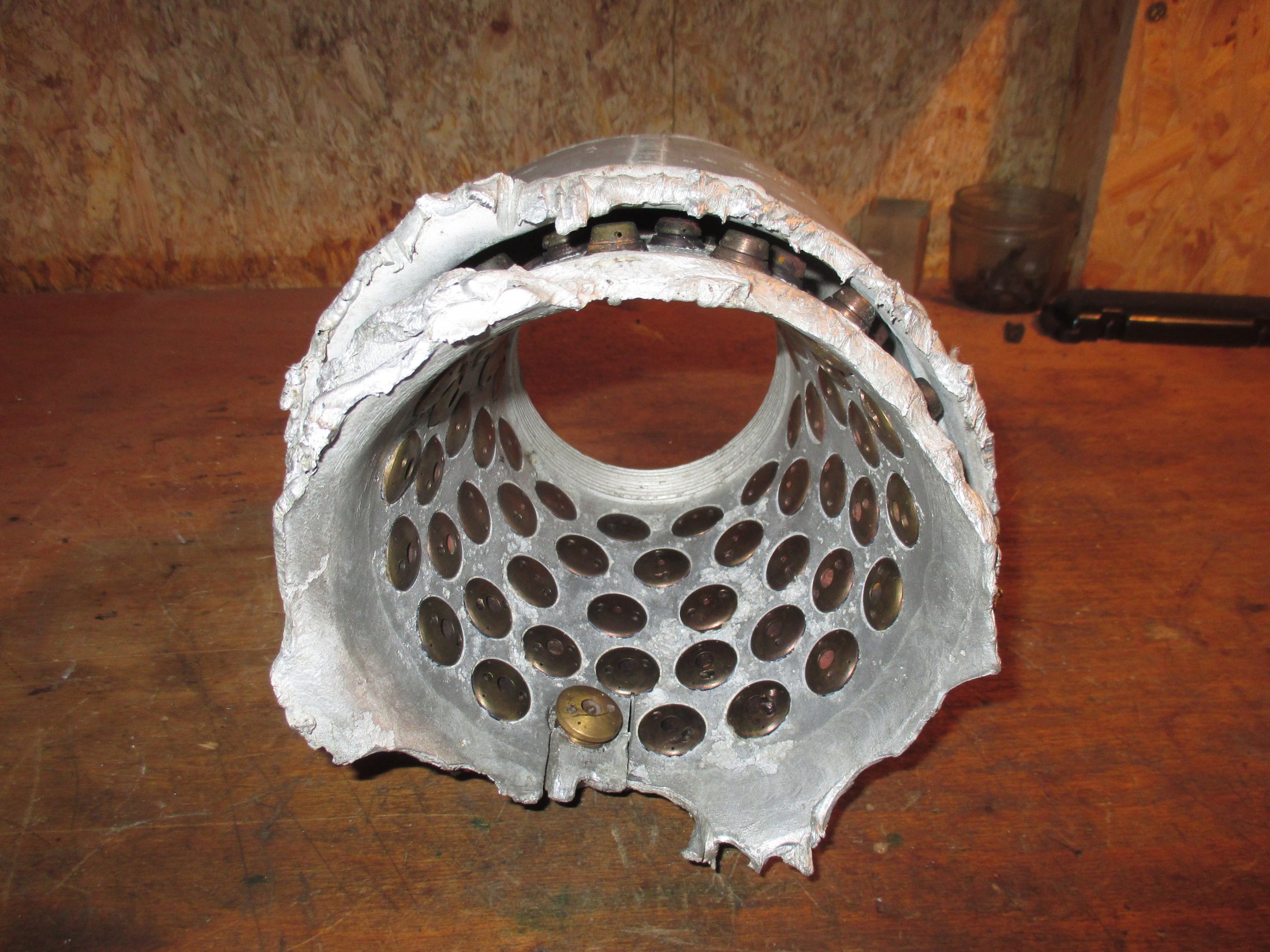
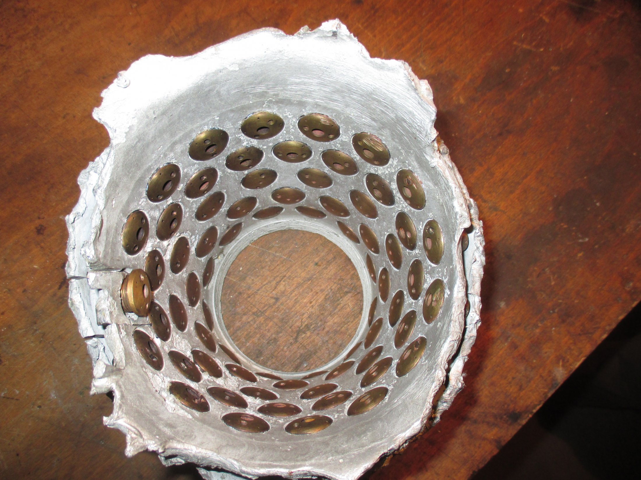
Relic of prototype A4 25-ton 1940/41 aluminium injector head basket (or pre-chamber) showing 68 copper alloy inserts in 5 rows. The standard configuration would later become 44 inserts in 3 rows 25 2mm diameter drilled holes in two rows situated at row 3 and 4 (counting from nearest the camera). Photo courtesy Host Beck Collection
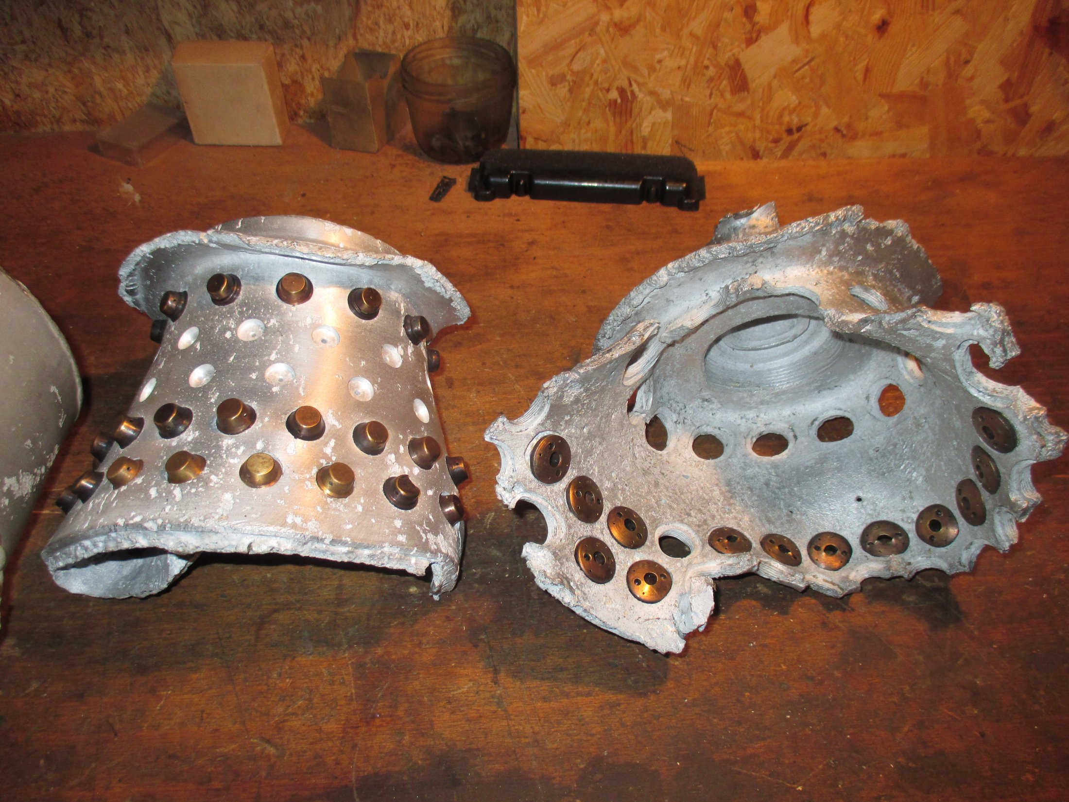
Parts of the 'Standard' series A aluminium head from 1941. The brass injector insert type and position pattern on the relics seem to be of the standard type but the pattern is non-standard in that higher volume injectors with three inlet apertures (two centrifugal and one central) have been place nearest the LOX injector. Photo courtesy Horst Beck
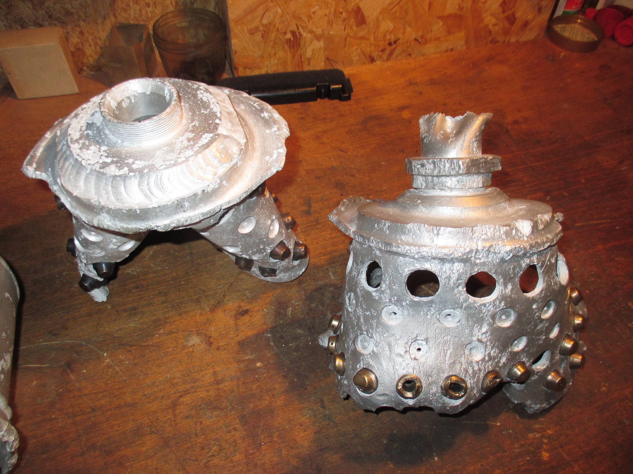
Part of the 'Standard' series A aluminium head from 1941/42
Part of the 'Standard' series A aluminium head from 1941/42
Part of the 'Standard' series A aluminium head from 1941 to early 1942. Showing the position of standard type LOX injector. The brass fuel injector inserts type and position pattern on the relic seem to be of the standard type with the row of 3 inlet aperture type inserts positioned furthest from the LOX injector. Photo courtesy Horst Beck Collection
Aluminium Injector basket with 68 inserts from 1940/41
Aluminium Injector basket with 68 inserts from 1940/41
Relic of A4 25-ton 1940/41 aluminium injector head basket (or pre-chamber) showing 68 copper alloy inserts in 5 rows. The standard configuration would later become 44 inserts in 3 rows 25 2mm diameter drilled holes in two rows situated at row 3 and 4 (counting from nearest the camera). Photo courtesy Host Beck Collection
Flown V2 thrust chamber relic from February 1945. Badly damaged from impact, this head shows 4 intact LOX input pipe connections as well as exposed fuel injector inserts positioned in the inner wall of the injector pots. The inner and outer walls of the head are also conveniently exposed on this exhibit. Photo www.v2rockethistory.com
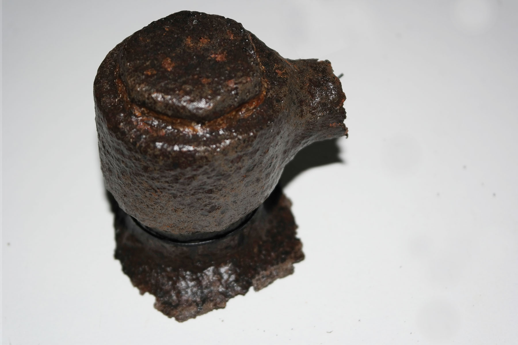
Injector pot cutaway: fuel & LOX injectors with LOX cap.
Injector pot cutaway: fuel & LOX injectors with LOX cap.
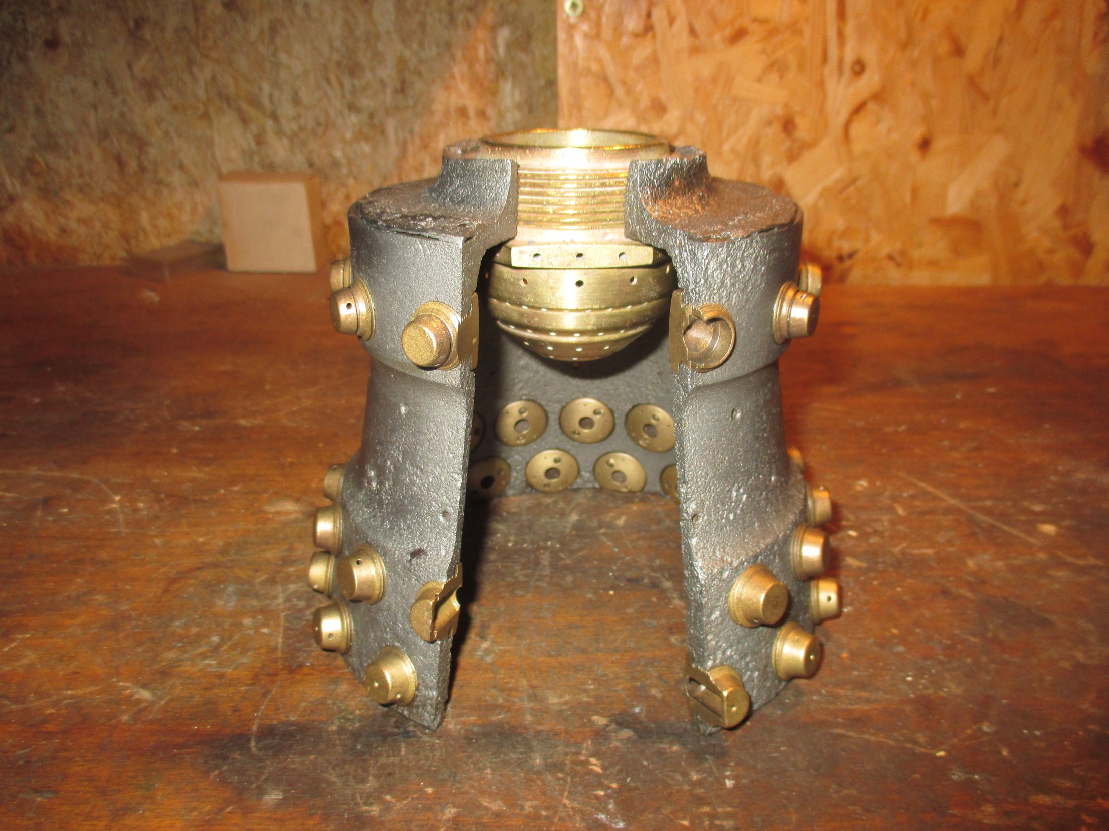
V2 Rocket History Museum Relic: This cutaway presentation shows one of the V2's 18 combined fuel and liquid oxygen (LOX) injector 'pots'. The LOX injector transit cap is also shown. The pot shown here is sometimes incorrectly referred to as a pre-burner or pre chamber - a mixer or diffuser pot probably describes its role more accurately.
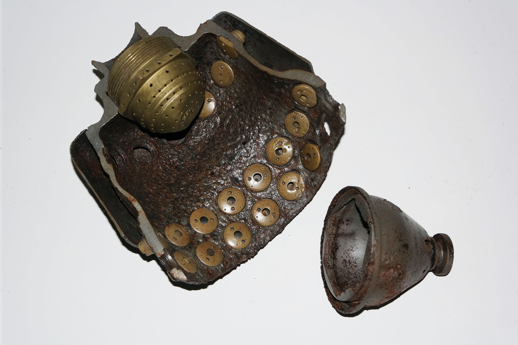
Injector pot cutaway: fuel & LOX injectors with fitted LOX cap.
Injector pot cutaway: fuel & LOX injectors with fitted LOX cap.
This relic from the V2 Rocket History collection shows a cutaway presentation of one of the V2's 18 combined fuel and liquid oxygen (LOX) injector 'pots'. The LOX injector transit cap is also shown fitted over the LOX injector.
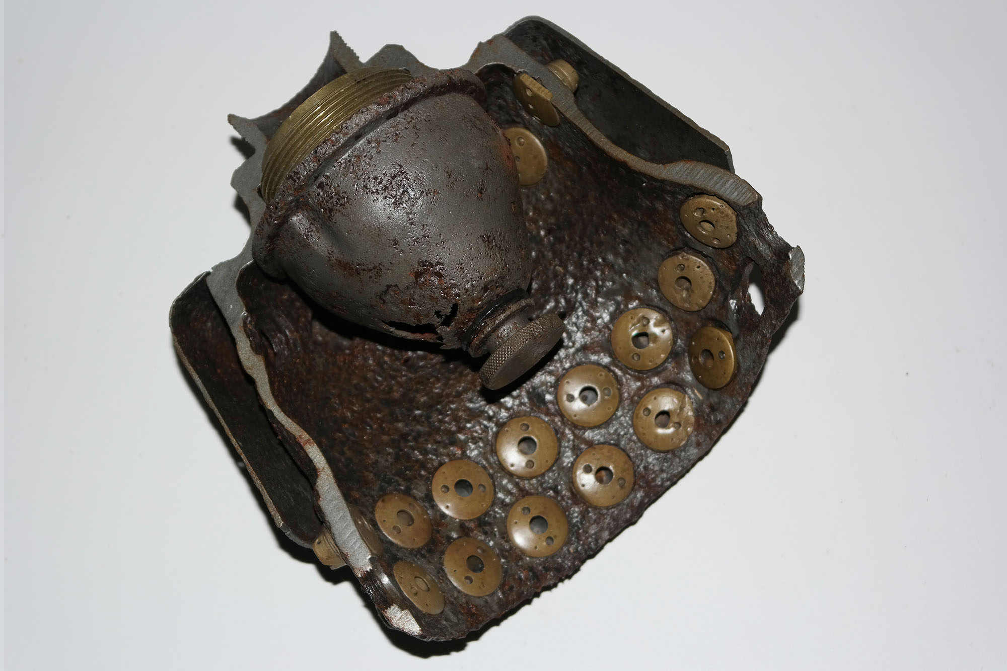
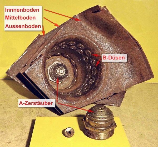
Cutaway of one the V2's pre-chambers with fuel and LOX injectors.
Cutaway of one the V2's pre-chambers with fuel and LOX injectors.
One of the V2's 18 injector pots showing fuel and LOX injector copper alloy inserts. The spray head A is for liquid oxygen (LOX) and the numerous small injectors lining the chamber are for the fuel. The term pre-chamber is a throw-back to a time when combustion systems developed at the Kummersdorf test facility had a closed structure rather than the open bucket design seen here. Image Horst Beck Collection
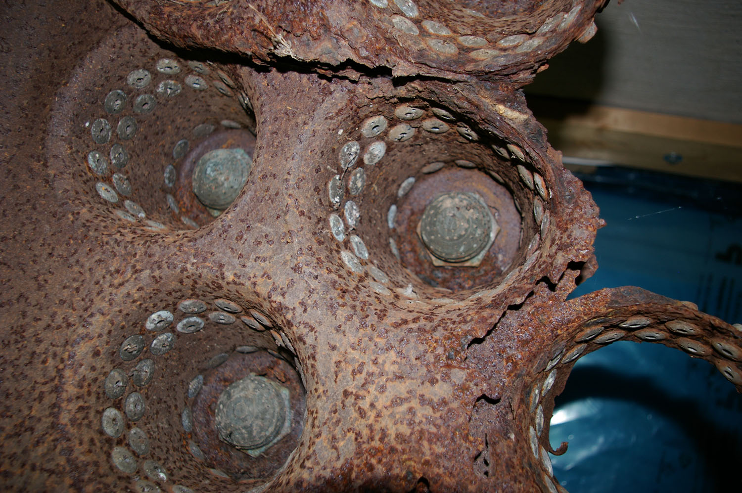
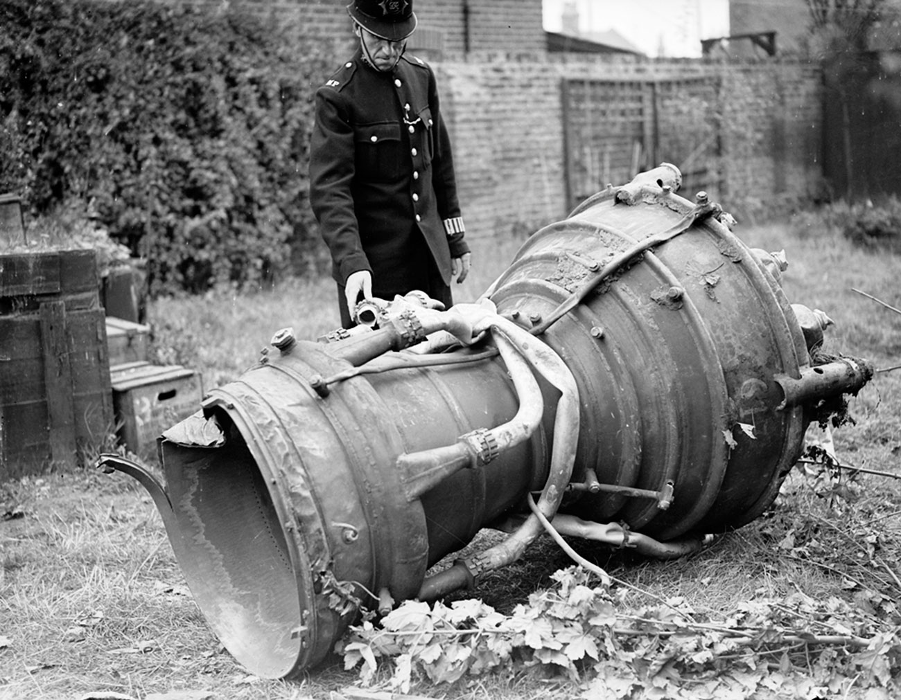
V2 engine part from a missile fired from Walcheren, Serooskerke, Vrederust, by battery no 444, at around 7am on September 17th 1944. The missile impacted East Ham with a direct hit on houses. Killing 6 people with 15 seriously injured. Much of the rocket debris was taken to the East Ham police station for examination by the military authorities. Information porovided by www.v2rocket.com.
Examination of V2 missile thrust chamber. Sections of two of the large bore aluminium alcohol inlet manifold feed pipes and two thin steel veil colling supply pipes are still attached. The distinctive heat expansion relief loop can be seen on one of the pipes.
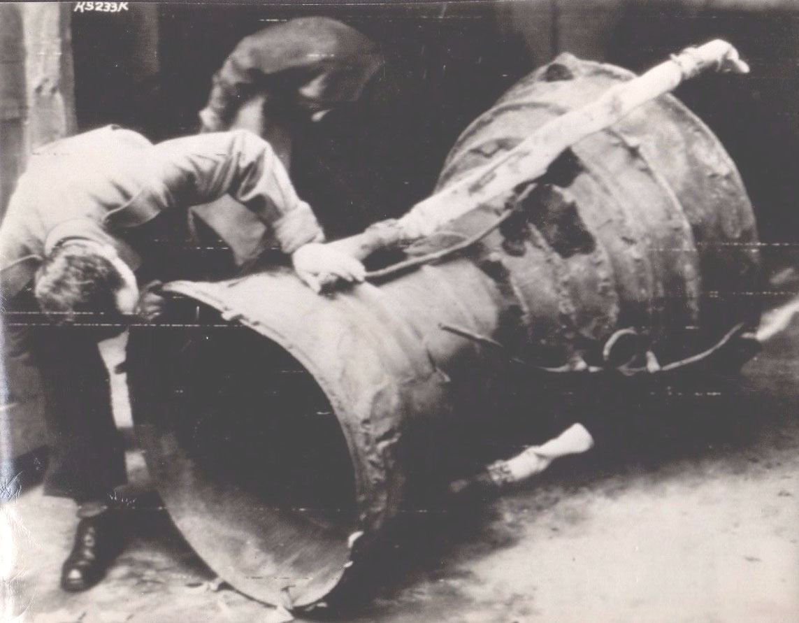
Image shows interior of production series (combat relic) V2 missile propellent injector pre-mixer pots. Three post in the picture are intact, others seem in the picture have been destroyed in the impact. This engine part was recovered from a combat impact East of London. Impact date: February 1945
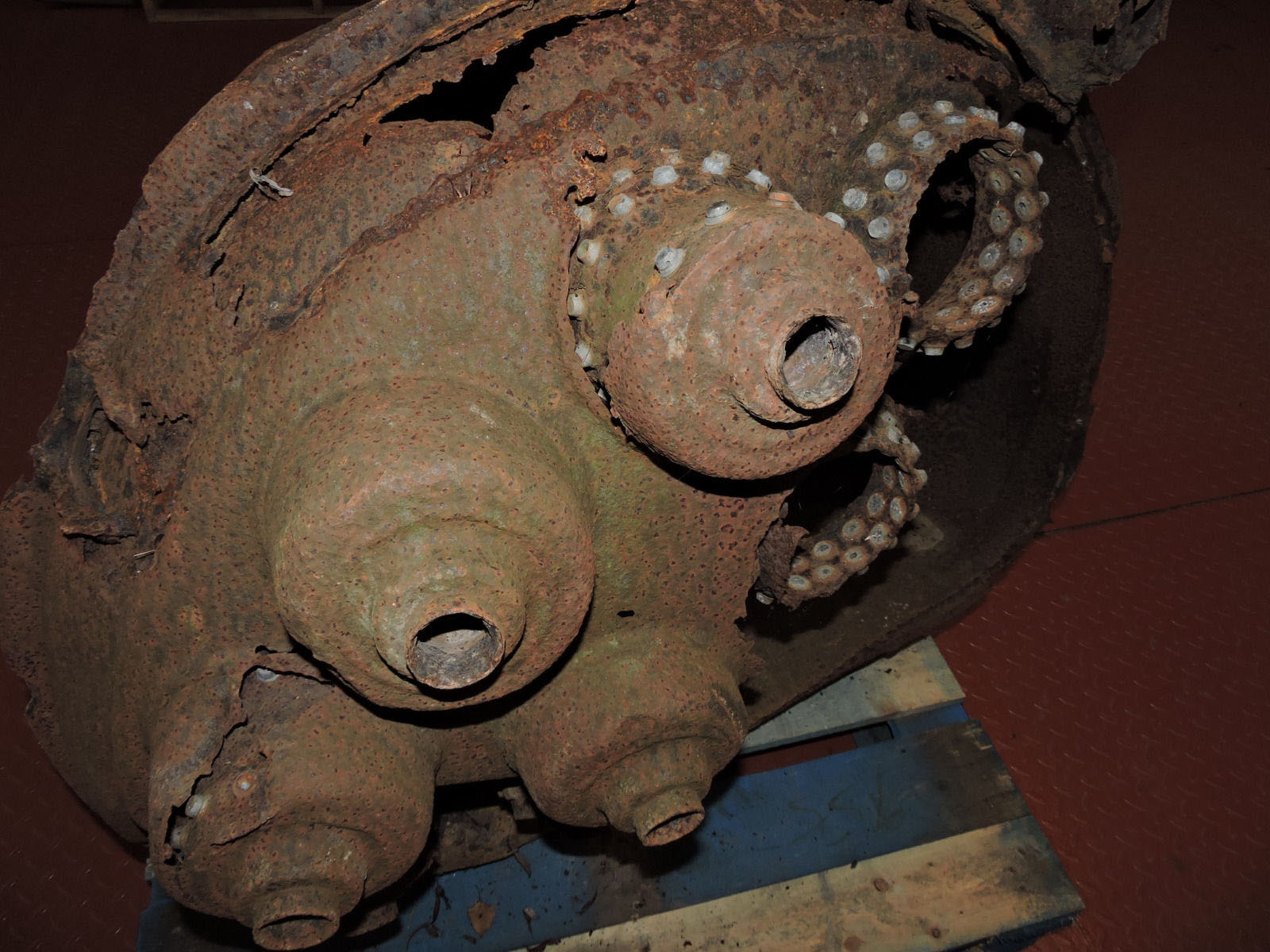
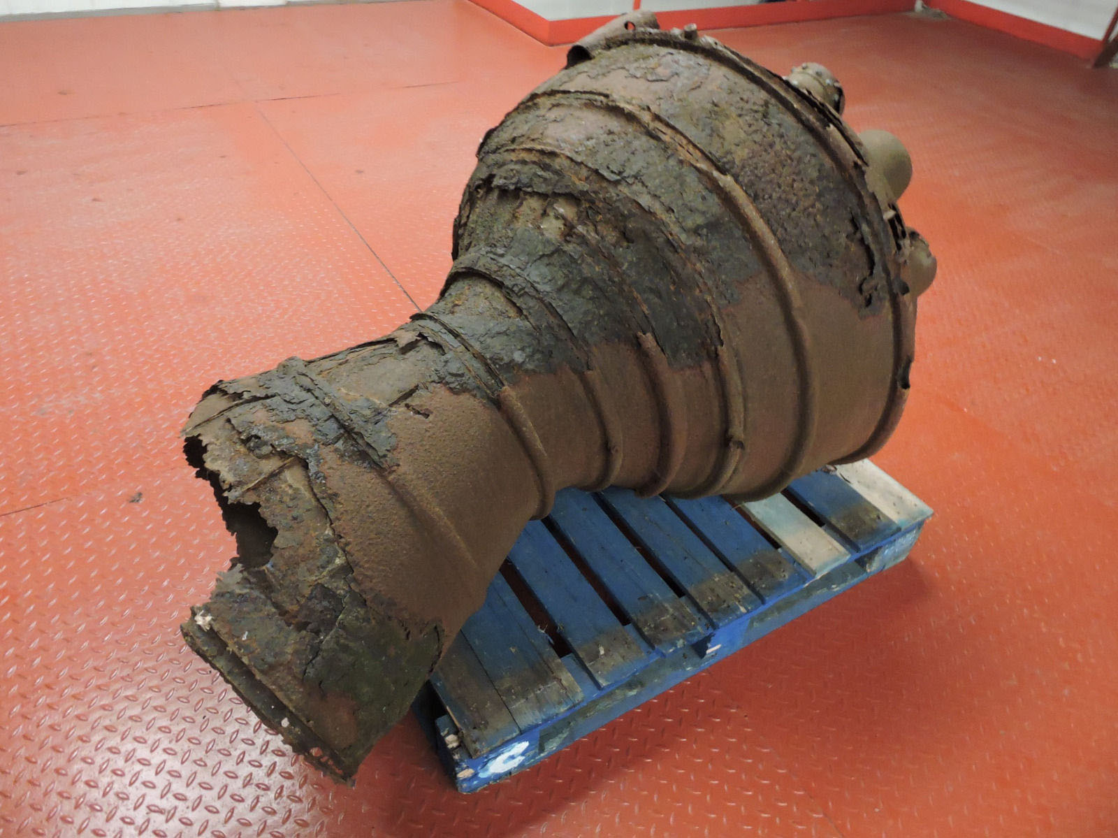
V2 thrust chamber with damaged (missing) inlet manifold
V2 thrust chamber with damaged (missing) inlet manifold
Recovered from Great Warley impact: February 1945. This chamber has a production use order number of 33 painted crudely on topmost segment. This number, to indicate rank in batch, was added shortly after manufacture to ensure the chamber was selected by the missile assembly crews in the correct order; that is on a newest-last basis to make sure that the oldest chambers were employed in missile construction operations first.
A tutor in computer-aided design at Moscow State Technical University, Alexander Savochkin says he finds relaxation in transcribing 75-year-old missile plans into modern 3D CAD models. He lives with his very patient wife in the leafy suburbs of Moscow.