
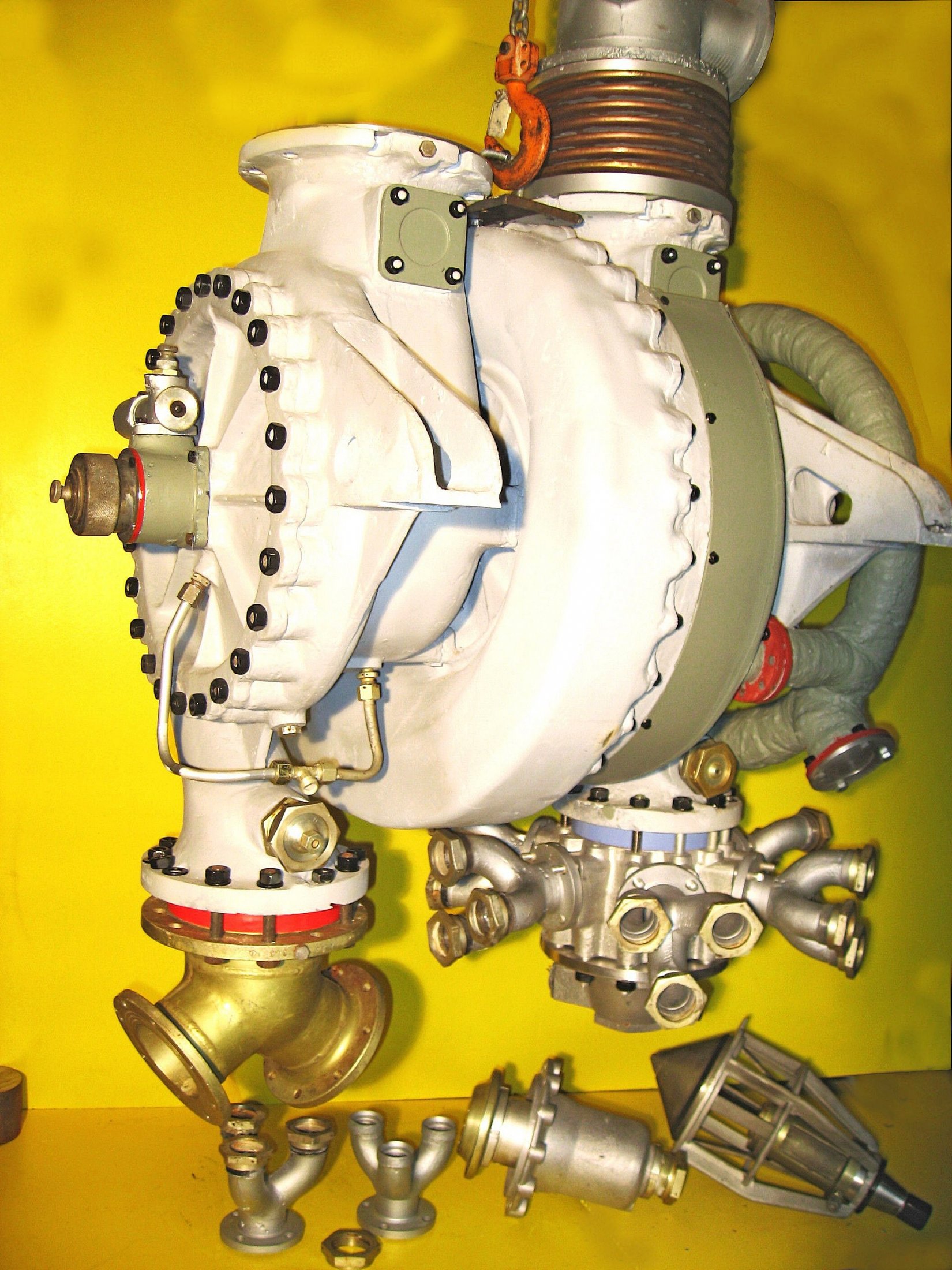
A4-V2 turbo-pump (TP) assembled from original and refurbished parts by Horst Beck. See previous image in this album for more details of TP.
The pale blue spacer that can be seen inserted between the lower LOX outlet flange (on the right of the TP) and the red spacer located in a similar position on the fuel outlet side (left) are critical adaptions to standardise the propellant flow on the basis of test runs performed on each TP. The red and blue spacers are chokes (essentially large washers) that were sized according to the needs of each individual pump. One or sometimes both spacer/washers would have a reduced holes to choke the flow volume to the correct rating relative to the other pump and the overall specifications.
The small pipe network, shown linking the underside of the fuel inlet case, with the bottom of the fuel pump (FP) case and the bearing area of the FP face plate, was used to allow a small continuous flow of propellant pass to the bearings as lubricant - the surplus was dumped overboard via the unconnected union in the middle of the pipework (and nearest viewer). A similar propellant lubrication system was used on the LOX pump - critically LOX can not be allowed to come into contact with conventional organic lubricants as there is a risk of an explosion. So using the material being pumped as the bearing lubricant is a good solution to this problem. Image courtesy Horst Beck Collection

Be the first to comment