
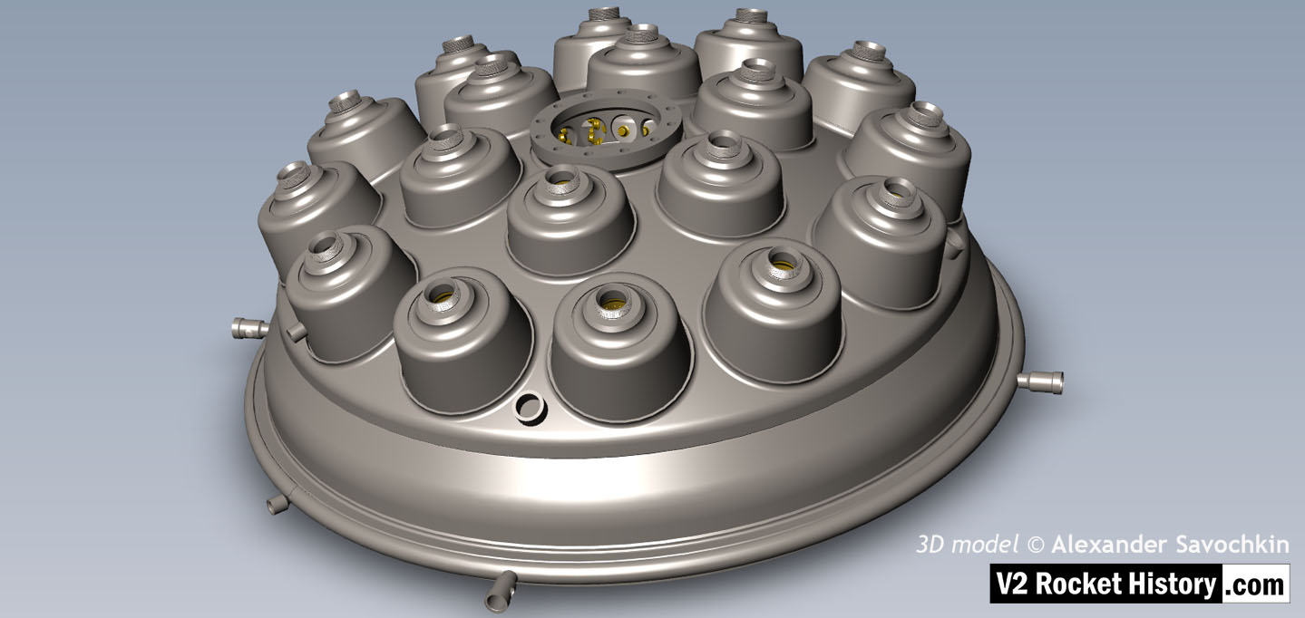
Another view of injector head showing liquid propellant (LOX and fuel) diffuser cups and head fuel valve seating ring at centre, (see other images for insert and position nomenclature). Visible immediately below the valve seat are the large connecting holes that allow fuel to flow from the inlet manifold and cooling jacket to the injector space (some brass injector inserts can be seen through the holes) after the head fuel valve is released to be opened by the turbo-pump supply pressure. The four veil cooling inlet connectors are well shown as are two of the outlet connection holes immediately above them. 3D model by Alexander Savochkin

Be the first to comment